1994 JEEP CHEROKEE diagram
[x] Cancel search: diagramPage 377 of 1784
REAR SPEAKERS
²Radio OFF, radio connector disconnected. Measure
resistance between radio left rear feed and return
connector pins. Measure between right rear feed and
return connector pins. The meter should read 5 to 8
ohms. If meter reading is correct remove radio for
service. If not, repair wiring or replace speakers as
required.
DISTORTED AUDIO OUTPUT ON ONE OR
MORE SPEAKERS
²With the radio ON, substitute known good speaker
or speakers. If the sound is still distorted, remove ra-
dio for service.
WEAK OR NO RECEPTION; NO AUDIO
OUTPUT; BACKGROUND NOISE PRESENT
Ignition switch in ON, radio ON.
²Inspect antenna cable and connector at radio and
tighten or repair as necessary.
²Unplug coax cable and connectors from radio. Mea-
sure resistance from center conductor to coaxial
shield. The meter should read infinite resistance
(open). If it does not, replace antenna assembly.
²Measure resistance of antenna mast to tip of cen-
ter conductor at radio end of cable. The meter should
read 0 to 0.5 ohms. If it does not, replace lead-in ca-
ble or antenna assembly.
²Measure resistance from coaxial shield to chassis
ground (vehicle body). The meter should read zero
ohms. If it does not, ground antenna base to vehicle
body, or replace antenna assembly as required
For all problems with no or low audio output
not resolved by these tests, remove radio for ser-
vice.
MEMORY DOES NOT OPERATE
²Inspect (F16 in Power Distribution Center-YJ),
(#9 in Fuse Panel-XJ) fuse and replace if necessary.
²Measure voltage at battery side of previously ref-
erenced fuse. There should be 12 volts at battery side
of fuse. If not, check the Maxi fuse.
Refer to Group 8W - Wiring Diagrams.
²Measure voltage at radio connector pin 4. There
should be 12 volts. If meter reading is correct, re-
move radio for service. If not, repair open from fuse.
RADIO DISPLAY ILLUMINATION (PARKLAMPS
AND HEADLAMPS OPERATING NORMALLY)
Headlamp switch OFF, radio ON.
²Measure voltage at radio connector pin 10. There
should be 12 volts. If not, go to next step. If OK, re-
move radio for repair by authorized outlet.
²Measure voltage at illumination relay pin 3. There
should be 12 volts. If 12 volts present, replace illumi-
nation relay. If not, repair open in circuit.RADIO DISPLAY ILLUMINATION DIMMING CIRCUIT
Turn headlamp switch to PARKLAMPS for
voltage tests; turn headlamp switch to OFF for
resistance tests.
²Separate relay connector from radio illumination
relay. Measure resistance from relay connector pin 2
to a clean chassis ground. The meter should read
zero ohms. If not, repair open between relay connec-
tor and ground.
²Measure voltage at radio illumination relay pin 5.
There should be battery voltage. If not repair open
from headlamp switch.
²Measure voltage at radio illumination relay pin 4.
Voltage should vary with dimmer switch. If OK, go
to next step. If not, repair open circuit between pin 4
and interior lamp rheostat.
²Measure voltage at radio illumination relay pin
10. Voltage should vary with dimmer switch. If OK,
remove radio for repair by authorized outlet. If not,
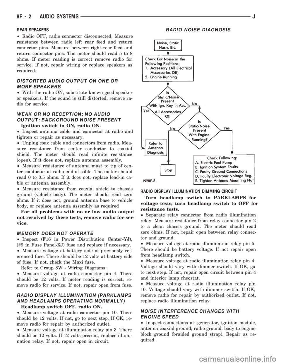
replace radio illumination relay.NOISE INTERFERENCE CHANGES WITH
ENGINE SPEED
²Inspect connections at: generator, ignition module,
antenna coaxial ground, radio ground, body to engine
block ground (braided ground strap). Repair as re-
quired.
RADIO NOISE DIAGNOSIS
8F - 2 AUDIO SYSTEMSJ
Page 386 of 1784
HORNS
CONTENTS
page page
GENERAL INFORMATION.................. 1
HORN SWITCH (HORN PAD) REPLACEMENT . . 3
TORQUE SPECIFICATIONS................. 3XJ ..................................... 1
YJ ..................................... 2
GENERAL INFORMATION
For XJ/YJ vehicles battery voltage is applied to the
horn relay through a fuse.
When the horn switch is depressed, the horn relay
is grounded, pulling the contact closed and providing
battery voltage to the horns.
A slip ring and brush arrangement in the steering
wheel allows the switch circuit to maintain contact
while allowing rotation of the steering wheel.On XJ models, a cadmium-plated ground
screw is used to attach the horn(s) to the body.
Do not substitute other types of ground screws
as they may become corroded and cause a loss
of ground.
XJ
REPLACEMENT
(1) Raise and support the vehicle.
(2) Remove the splash shield.
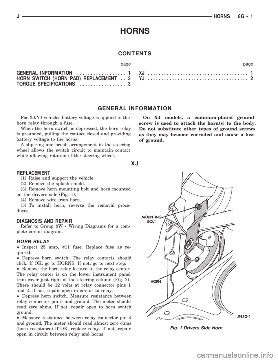
(3) Remove horn mounting bolt and horn mounted
on the drivers side (Fig. 1).
(4) Remove wire from horn.
(5) To install horn, reverse the removal proce-
dures.
DIAGNOSIS AND REPAIR
Refer to Group 8W - Wiring Diagrams for a com-
plete circuit diagram.
HORN RELAY
²Inspect 25 amp, #11 fuse. Replace fuse as re-
quired.
²Depress horn switch. The relay contacts should
click. If OK, go to HORNS. If not, go to next step.
²Remove the horn relay located in the relay center.
The relay center is on the lower instrument panel
trim cover just right of the steering column (Fig. 2).
There should be 12 volts at relay connector pins 1
and 2. If not, repair open in circuit to relay.
²Depress horn switch. Measure resistance between
relay connector pin 5 and ground. The meter should
read zero ohms. If not, repair open to horn switch
ground.
²Measure resistance between relay connector pin 4
and ground. The meter should read almost zero ohms
(horn resistance) If OK, replace relay. If not, repair
open in circuit between relay and horns.
Fig. 1 Drivers Side Horn
JHORNS 8G - 1
Page 387 of 1784
HORNS
²Disconnect horn connector. Depress horn switch.
There should be 12 volts at the horn connector. If
not, repair open to relay.
²Measure the resistance between the horn bracket
and chassis ground. The meter should read zero
ohms. If not, check mounting screw for corrosion and
replace as necessary.
²If above steps do not identify a problem, replace
horns.
YJ
Wrangler/YJ horns are located on the drivers side
inner fender.
REPLACEMENT
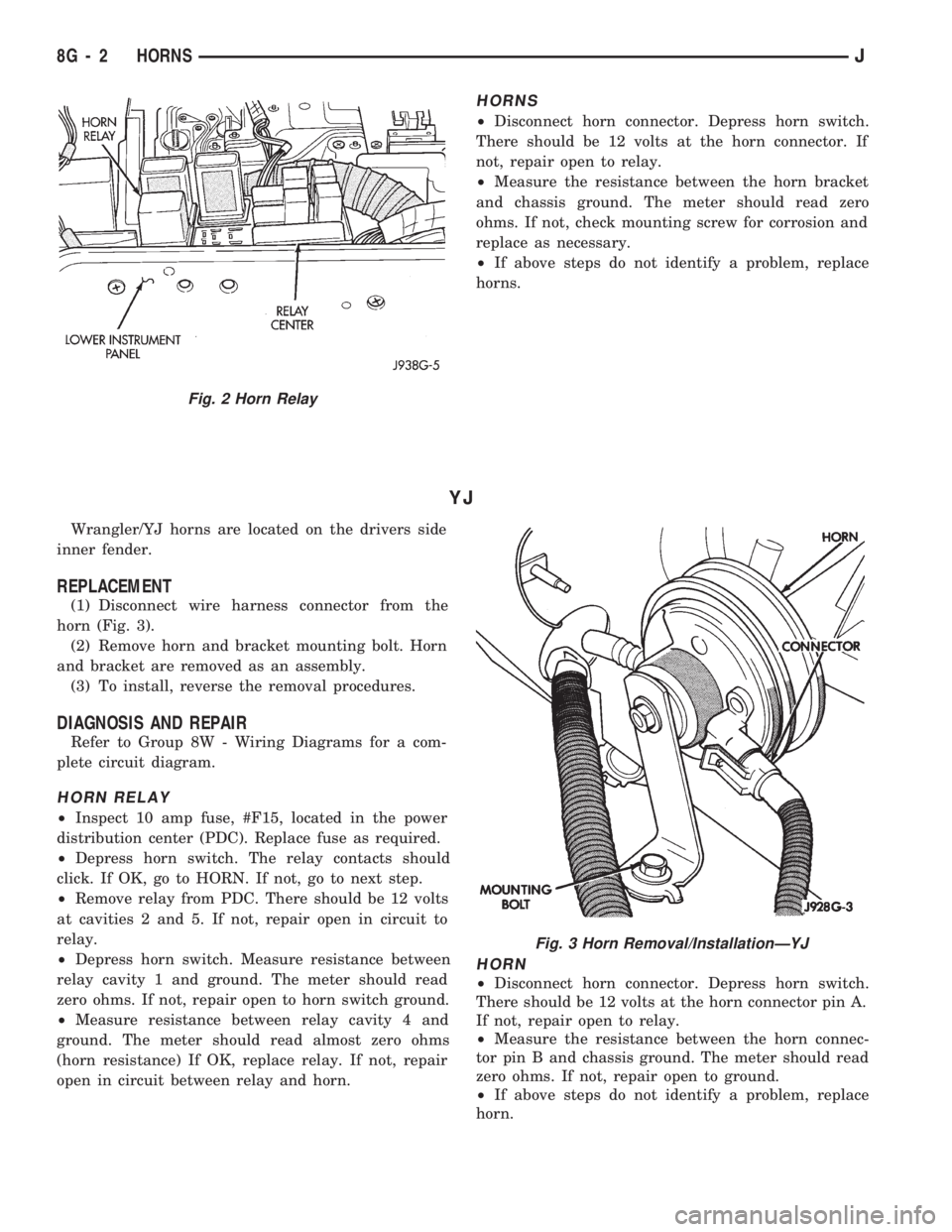
(1) Disconnect wire harness connector from the
horn (Fig. 3).
(2) Remove horn and bracket mounting bolt. Horn
and bracket are removed as an assembly.
(3) To install, reverse the removal procedures.
DIAGNOSIS AND REPAIR
Refer to Group 8W - Wiring Diagrams for a com-
plete circuit diagram.
HORN RELAY
²Inspect 10 amp fuse, #F15, located in the power
distribution center (PDC). Replace fuse as required.
²Depress horn switch. The relay contacts should
click. If OK, go to HORN. If not, go to next step.
²Remove relay from PDC. There should be 12 volts
at cavities 2 and 5. If not, repair open in circuit to
relay.
²Depress horn switch. Measure resistance between
relay cavity 1 and ground. The meter should read
zero ohms. If not, repair open to horn switch ground.
²Measure resistance between relay cavity 4 and
ground. The meter should read almost zero ohms
(horn resistance) If OK, replace relay. If not, repair
open in circuit between relay and horn.
HORN
²Disconnect horn connector. Depress horn switch.
There should be 12 volts at the horn connector pin A.
If not, repair open to relay.
²Measure the resistance between the horn connec-
tor pin B and chassis ground. The meter should read
zero ohms. If not, repair open to ground.
²If above steps do not identify a problem, replace
horn.
Fig. 2 Horn Relay
Fig. 3 Horn Removal/InstallationÐYJ
8G - 2 HORNSJ
Page 394 of 1784
TEST PROCEDURES
INDEX
page page
Checking for Diagnostic Trouble Code......... 5
Electrical Tests at Powertrain Control Module.... 6
Electrical Tests at Servo.................... 5
Inoperative System........................ 5
Operational Check (Road Test)............... 7
Road Test............................... 5Speed Control Switch (Turn Signal Lever) Test . . . 7
Stop Lamp Speed Control Switch Test......... 7
Vacuum Supply Test....................... 7
Vehicle Speed Control System Electrical Tests . . . 5
Vehicle Speed Sensor Test.................. 5
ROAD TEST
Refer to Operational Check (Road Test) section to
verify reports of speed control system malfunction.
INOPERATIVE SYSTEM
Road test vehicle to verify reports of speed control
system malfunction. An inspection should be made
for loose electrical and vacuum connections at the
servo.
Check for correct installation of the vacuum check
valve in the hose from servo to vacuum source. The
word VAC on the valve must point toward the vac-
uum source.
Corrosion should be removed from electrical termi-
nals and a light coating of Mopar MultiPurpose
Grease, or equivalent, applied.
Inspection also should be made to verify that both
ends of the speed control cable are securely attached.
CHECKING FOR DIAGNOSTIC TROUBLE CODE
(1) When trying to verify a speed control system
electronic malfunction use a DRB scan tool to find
the cause (refer to Powertrain Diagnostic Procedures
manual).
If DRB is not available, the Diagnostic Trouble
Code (DTC) may be determined with the following
method:
(a) With key inserted in ignition switch, cycle
switch to ON position 3 times. On third cycle, leave
switch in ON position.
(b) After switch has been cycled 3 times, observe
Malfunction Indicator Lamp (CHECK ENGINE)
on instrument cluster. If a DTC is present, the code
will be displayed in a series of flashes representing
digits. Three flashes in rapid succession, a slight
pause, then 4 flashes in rapid succession would in-
dicate DTC 34.
(2) If a DTC 34 is observed, perform tests in the
sections Electrical Tests at Servo and Electrical Tests
at Powertrain Control Module.
If a DTC 15 is observed, perform test for a faulty
vehicle speed sensor.
(3) Correct any problems found when performing
these tests and recheck for DTC if changes were
made.
VEHICLE SPEED SENSOR TEST
For testing of the vehicle speed sensor and related
components, refer to Powertrain Diagnostic Proce-
dures manual.
VEHICLE SPEED CONTROL SYSTEM ELECTRICAL
TESTS
Vehicle speed control systems may be tested using
two different methods. One involves use of a DRB
scan tool. If this test method is desired, refer to Pow-
ertrain Diagnostic Procedures manual.
The other test method uses a voltmeter. The volt-
meter method is described in the following tests.
If any information is needed concerning wiring, re-
fer to Section 8W - Wiring Diagrams.
CAUTION: When test probing for voltage or conti-
nuity at electrical connectors, care must be taken
not to damage connector, terminals, or seals. If
these components are damaged, intermittent or
complete system failure may occur.
ELECTRICAL TESTS AT SERVO
(1) Turn ignition switch to the ON position. With
speed control switch in the ON position, setup a volt-
meter to read battery voltage and connect negative
lead to a good chassis ground.
(2) Disconnect 4-way connector going to servo
(Figs. 2 and 3). Blue wire with red tracer of main
harness 4-way connector should read approximately
battery voltage. If not, check for loose connections,
brake switch adjustment or, repair main harness as
necessary.
(3) Connect a jumper wire between male and fe-
male terminals of blue wire with red tracer. The
other 3 male terminals from servo should show bat-
tery voltage. If not, replace servo.
(4) Using an ohmmeter, connect one lead to a good
body ground. Touch other lead to black wire terminal
in 4-way connector of main harness. Meter should
show continuity. If not, repair ground circuit as nec-
essary.
JVEHICLE SPEED CONTROL SYSTEM 8H - 5
Page 402 of 1784

TURN SIGNALS AND HAZARD WARNING FLASHER
CONTENTS
page page
HAZARD LAMPSÐXJ.................... 1
HAZARD LAMPSÐYJ.................... 2
TURN SIGNALSÐXJ..................... 1TURN SIGNALSÐYJ..................... 2
TURN/HAZARD SWITCH REPLACEMENT - ALL
MODELS............................. 3
TURN SIGNALSÐXJ
Refer to Section 8W - Wiring Diagrams for cir-
cuit wiring diagram.
DESCRIPTION
With the turn signal lever in its up or down posi-
tion and the ignition switch in ACCESSORY or ON,
current flows through the:
²turn/hazard switch
²selected turn indicator bulb
²front and rear turn signal bulbs
²and the front side marker bulb.
With the headlamps OFF, the turn and front side
marker lamps flash in unison.With the headlamps
ON, the turn and front side marker lamps flash al-
ternately.
DIAGNOSISÐTURN SIGNAL INOPERATIVE
(1) A turn signal indicator that does not flash usu-
ally indicates a burned out turn signal bulb. Check
for and replace if defective. System should now func-
tion properly. If not, go to next step.
High generator output voltage can burn out
lamps rapidly.(2) Remove and inspect 20 amp #8 fuse. Replace if
necessary. If OK, go to next step.
(3) Remove turn flasher, light blue can, located in
upper left corner of fuse block.
(4) Turn ignition switch to ACCESSORY. Check
for battery voltage at flasher bottom cavity on fuse
block. If OK, go to next step. If not, repair open cir-
cuit in wiring between turn flasher and #8 fuse.
(5) Turn ignition switch to ACCESSORY. Move
turn signal lever up or down. Replace turn flasher
with known good flasher. The lamps should flash. If
not, replace original flasher and go to next step.
(6) Turn ignition switch to OFF. Follow procedure
for turn/hazard switch replacement to locate steering
column connector. Unplug connector.
(7) Turn ignition switch to ACCESSORY. Check
for battery voltage at connector terminal L. If OK,
replace turn/hazard switch and check that lamps
flash. If not, repair open circuit in wiring between
turn flasher and steering column connector terminal
L.
HAZARD LAMPSÐXJ
Refer to Section 8W - Wiring Diagrams for cir-
cuit wiring diagram.
DESCRIPTION
With the hazard switch ON, current flows through
the:
²hazard flasher
²the turn/hazard switch
²two front turn signal bulbs
²two rear turn signal bulbs
²two front side marker bulbs
²and two turn indicator bulbs.
All of these bulbs will flash on and off.
DIAGNOSISÐHAZARD LAMPS INOPERATIVE
(1) Inspect 20 amp #F13 fuse in Power Distribu-
tion Center (PDC). The PDC is located in the engine
compartment, passenger side. For location of fuse,check underside of PDC cover. Replace if necessary.
If OK, go to next step.
(2) Remove hazard flasher (tin can) located in fuse
block.
(3) Check for battery voltage at the terminal on
the right (3 o'clock). If OK, go to next step. If not, re-
pair open circuit in wiring between #F13 fuse and
hazard flasher right terminal.
(4) Replace hazard flasher with known good
flasher. Activate hazard warning switch. Lamps
should flash. If not, replace original flasher and go to
next step.
(5) Follow procedure for turn/hazard switch re-
placement to locate steering column connector. Un-
plug connector.
(6) Check for battery voltage at connector terminal
K. If OK, replace turn/hazard switch. If not, repair
open circuit in wiring between hazard flasher and
steering column connector terminal K.
JTURN SIGNALS AND HAZARD WARNING FLASHER 8J - 1
Page 403 of 1784

TURN SIGNALSÐYJ
Refer to Section 8W - Wiring Diagrams for cir-
cuit wiring diagram.
DESCRIPTION
With the turn signal lever in its up or down posi-
tion and the ignition switch in ACCESSORY or ON,
current flows through the:
²turn/hazard switch
²selected turn indicator bulb
²front and rear turn signal bulbs
²front side marker bulb
With the headlamps OFF, the turn and side
marker lamps flash in unison.With the headlamps
ON, the turn and side marker lamps flash alter-
nately.
DIAGNOSINGÐTURN SIGNAL INOPERATIVE
(1) A turn signal indicator that does not flash usu-
ally indicates a burned out turn signal bulb. Check
for and replace if defective. System should now func-
tion properly. If not, go to next step.
High generator output voltage can burn out
lamps rapidly.
(2) Locate fuse block under driver's side of instru-
ment panel.(3) Remove and inspect 15 amp #4 fuse. Replace if
necessary. If OK, go to next step.
(4) Remove turn flasher, light blue can, located in
fuse block.
(5) Turn ignition switch to ACCESSORY. Check
for battery voltage at cavity on left (closest to hazard
flasher can). If OK, go to next step. If not, repair
open circuit in wiring between turn flasher and #4
fuse.
(6) Turn ignition switch to ACCESSORY. Move
turn signal lever up or down. Replace turn flasher
with known good flasher. The lamps should flash. If
not, replace original flasher and go to next step.
(7) Turn ignition switch to OFF. Follow procedure
for turn/hazard switch replacement to locate steering
column connector. Unplug connector.
(8) Turn ignition switch to ACCESSORY. Check
for battery voltage at connector terminal L. If OK,
replace turn/hazard switch. If not, repair open circuit
in wiring between turn flasher and steering column
connector terminal L.
HAZARD LAMPSÐYJ
Refer to Section 8W - Wiring Diagrams for cir-
cuit wiring diagram.
DESCRIPTION
With the hazard switch ON, current flows through
the:
²hazard flasher
²turn/hazard switch
²two front turn signal bulbs
²two rear turn signal bulbs
²two front side marker bulbs
²two turn indicator bulbs.
All of these bulbs will flash on and off.
DIAGNOSISÐHAZARD LAMPS INOPERATIVE
(1) Inspect 20 amp #F5 fuse in Power Distribution
Center (PDC). The PDC is located in the engine com-
partment, passenger side. For location of fuse, check
underside of PDC cover. Replace if necessary. If OK,
go to next step.(2) Remove hazard flasher (tin can) located in fuse
block.
(3) Check for battery voltage at the terminal on
the left. If OK, go to next step. If not, repair open cir-
cuit in wiring between #F5 fuse and hazard flasher
left terminal.
(4) Replace hazard flasher with known good
flasher. Activate hazard warning switch. Lamps
should flash. If not, replace original flasher and go to
next step.
(5) Follow procedure for turn/hazard switch re-
placement to locate steering column connector. Un-
plug connector.
(6) Check for battery voltage at connector terminal
K. If OK, replace turn/hazard switch. If not, repair
open circuit in wiring between hazard flasher and
steering column connector terminal K.
8J - 2 TURN SIGNALS AND HAZARD WARNING FLASHERJ
Page 419 of 1784
CAUTION: DO NOT move the wiper switch to DE-
LAY with the intermittent wiper module removed
from the circuit. If the switch is moved to the DE-
LAY position during the next step, the switch will
be damaged.
²Test wiper operation in LOW and HIGH speed
modes, and test washer operation. If these modes
were inoperative, but are OK now, replace failed in-
termittent wiper module.
(4) To test the wiper/washer switch, see Wiper
Switch Testing. Turn ignition switch to OFF. Posi-
tion the wiper switch as indicated, and back probe
switch side of wiper switch connector. If switch tests
OK, go to step 5. If not, replace switch and go to step
6.
(5) To further test the wiper/washer switch, turn
ignition switch to ACCESSORY or ON. Position the
wiper switch as indicated in the tests below, and
back probe switch side of wiper switch connector.
²Measure voltage at terminal E with wiper switch
in LOW, MIST and with washer switch depressed.
Meter should read battery voltage. If not, replace
switch.
²Measure voltage at connector terminal C with
wiper switch in HIGH. Meter should read battery
voltage. If not, replace switch.
²With wiper switch in LOW or HIGH, measure
voltage at connector terminal F, then move wiper
switch to OFF. Meter shold read battery voltage un-
til wipers park and then zero volts. If OK, go to step
6. If not, check wiring to wiper motor, then go to step
6.
(6) To test the wiper motor, turn the ignition
switch to ACCESSORY or ON. Position the wiper
switch and back probe the motor connector as indi-
cated.
²Wiper switch in any position, measure voltage at
terminal B. Meter should read battery voltage. If not,
repair wiring from circuit breaker.
²Wiper switch in LOW, measure voltage at termi-
nal A. Meter should read battery voltage. If OK, but
wipers do not operate, replace failed wiper motor. If
not, repair wiring from switch or intermittent wiper
module connector.
²Wiper switch in HIGH, measure voltage at termi-
nal H. Meter should read battery voltage. If OK, but
wipers do not operate, replace failed wiper motor. If
not, repair wiring from switch or intermittent wiper
module connector.
²Wiper switch in LOW or HIGH, voltmeter con-
nected to terminal D. Turn wiper switch to OFF and
observe meter. Meter should read battery voltage
when switch goes to OFF, then zero volts after wip-
ers park. If battery voltage is present, but wipers fail
to park; or, if no battery voltage present, replace
failed wiper motor.DIAGNOSING NON-INTERMITTENT WINDSHIELD
WASHER
Refer to Group 8W - Wiring Diagrams.
(1) Measure resistance from washer pump connec-
tor terminal B to a clean chassis ground. Meter
should read zero ohms. If not, repair open between
terminal B and ground.
(2) Turn ignition switch to ON and press washer
switch.
²Measure voltage at switch connector terminal B.
Meter should read battery voltage. If not, replace
wiper/washer switch.
²Measure voltage at washer pump connector termi-
nal A. Meter should read battery voltage. If OK, re-
place pump. If not, repair open between switch
connector and pump connector.
DIAGNOSING INTERMITTENT WINDSHIELD
WASHER
Refer to Group 8W - Wiring Diagrams.
(1) Measure resistance from washer pump connec-
tor terminal B to a clean chassis ground. Meter
should read zero ohms. If not, repair open between
terminal B and ground.
(2) Turn ignition switch to ON and rotate washer
switch tab forward.
²Measure voltage at wiper/washer switch connector
terminal B located at intermittent wipe module.
Meter should read battery voltage. If not, replace
wiper switch.
²Measure voltage at intermittent wipe module con-
nector terminal B (to washer pump). Meter should
read battery voltage. If not, replace intermittent
wipe module.
²Measure voltage at washer pump connector termi-
nal A. Meter should read battery voltage. If OK, re-
place pump. If not, repair open from intermittent
wipe module connector terminal B.
REAR WIPER ARM REPLACEMENT
(1) Install wiper arm remover, Snap On A192 or
equivalent, on wiper arm (Fig. 11). Lift arm and then
remove from pivot shaft.
CAUTION: Do not use a screwdriver or other prying
tool to remove an arm. This may distort it in a way
that will allow it to come off the pivot shaft in the
future, despite how carefully it is installed. NEVER
push or bend the spring clip in the base of the arm
in an attempt to release the arm. This clip is self re-
leasing.
(2) To install, reverse the removal procedure.
(3) Wet the window and check the park position by
operating the wiper motor several times.
8K - 12 WINDSHIELD WIPERSJ
Page 421 of 1784
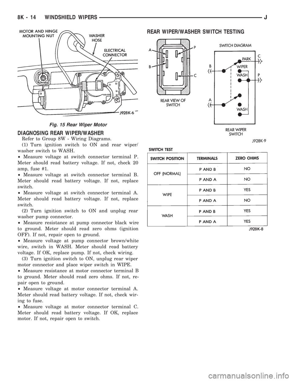
DIAGNOSING REAR WIPER/WASHER
Refer to Group 8W - Wiring Diagrams.
(1) Turn ignition switch to ON and rear wiper/
washer switch to WASH.
²Measure voltage at switch connector terminal P.
Meter should read battery voltage. If not, check 20
amp, fuse #1.
²Measure voltage at switch connector terminal B.
Meter should read battery voltage. If not, replace
switch.
²Measure voltage at switch connector terminal A.
Meter should read battery voltage. If not, replace
switch.
(2) Turn ignition switch to ON and unplug rear
washer pump connector.
²Measure resistance at pump connector black wire
to ground. Meter should read zero ohms (ignition
OFF). If not, repair open to ground.
²Measure voltage at pump connector brown/white
wire, switch in WASH. Meter should read battery
voltage. If OK, replace pump. If not, check wiring.
(3) Turn ignition switch to ON, unplug rear wiper
motor connector and place wiper switch in WIPE.
²Measure resistance at motor connector terminal B
to ground. Meter should read zero ohms. If not, re-
pair open to ground.
²Measure voltage at motor connector terminal A.
Meter should read battery voltage. If not, check wir-
ing to fuse.
²Measure voltage at motor connector terminal C.
Meter should read battery voltage. If OK, replace
motor. If not, repair open to switch.
REAR WIPER/WASHER SWITCH TESTING
Fig. 15 Rear Wiper Motor
8K - 14 WINDSHIELD WIPERSJ