1994 JEEP CHEROKEE radiator cap
[x] Cancel search: radiator capPage 17 of 1784
CAUTION: Do not overfill the engine crankcase with
oil. This will cause oil aeration and result in a de-
crease in the engine oil pressure.
(9) Start the engine and observe the oil pressure
gauge or warning lamp. If the pressure does not in-
crease or the warning lamp does not go out, stop the
engine and determine the cause of the problem.
USED ENGINE OIL DISPOSAL
Care should be exercised when disposing used en-
gine oil after it has been drained from a vehicle en-
gine. Refer to the WARNING listed above.
COOLING SYSTEM
WARNING: USE EXTREME CAUTION WHEN RE-
MOVING THE RADIATOR CAP IF THE ENGINE IS
OPERATING. DO NOT PUT YOUR HANDS NEAR
THE DRIVE BELT(S), PULLEYS OR FAN BLADE. DO
NOT STAND IN A DIRECT LINE WITH THE FAN
BLADE.
RECOMMENDED MAINTENANCE
The engine coolant level should be determined at
least once a month and more often during periods of
hot weather. Add coolant as necessary.
COOLANT LEVEL
With the engine at normal operating temperature,
observe the coolant level in thecoolant recovery bot-
tle. The coolant level must be at least above the ADD
mark and preferably at the FULL mark. Add coolant
to the coolant recovery bottleonly, if necessary.
REQUIRED MAINTENANCE
Check coolant level, and inspect condition of cool-
ing system hoses and clamps after each 12 000-km
(7,500-miles).
Initially, coolant must be drained and cooling sys-
tem flushed and filled after the first 36 months of op-
eration. Thereafter, after each 24-months interval of
vehicle operation.
RECOMMENDED MAINTENANCE
The engine cooling system should be inspected for
proper operation and for component failure at least
every 12 months.
WARNING: IF THE ENGINE HAS BEEN RECENTLY
OPERATED, USE EXTREME CARE WHEN REMOV-
ING THE RADIATOR CAP TO AVOID SCALDING
WITH HOT, PRESSURIZED COOLANT.
For additional information, refer to Section 7, Cool-
ing System.COOLANT FREEZE PROTECTION
Jeeptcooling systems contain a 50/50 mixture of
anti-freeze and distilled water coolant. This is the
recommended coolant mixture for most ambient tem-
peratures. The factory-installed anti-freeze is formu-
lated to prevent corrosion on all cooling system metal
surfaces.
The degree of coolant freeze protection should be
tested every 12 months. If the coolant is contami-
nated orrustyin appearance, cooling system should
be drained and filled with a 50/50 mixture of fresh
coolant. For additional information, refer to Group
7ÐCooling System.
ENGINE AIR CLEANER FILTER ELEMENT
RECOMMENDED MAINTENANCE
Engine performance and fuel economy can be af-
fected by a restricted air cleaner filter. The filter
should be inspected on a regular basis for excessive
air restriction.
If the filter element is saturated with oil, replace
the filter element.
REQUIRED MAINTENANCE
Engine air cleaner filter must be replaced after
each 48 000-km (30,000-miles).
If a vehicle is frequently operated in dusty
areas, the air cleaner filter should be inspected
often.
FILTER ELEMENT SERVICE/REPLACEMENT
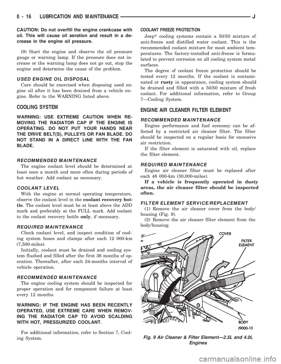
(1) Remove the air cleaner cover from the body/
housing (Fig. 9).
(2) Remove the air cleaner filter element from the
body/housing.
Fig. 9 Air Cleaner & Filter ElementÐ2.5L and 4.0L
Engines
0 - 16 LUBRICATION AND MAINTENANCEJ
Page 234 of 1784
COOLING SYSTEM
CONTENTS
page page
DIAGNOSIS............................. 4
ENGINE ACCESSORY DRIVE BELTS........ 31
ENGINE BLOCK HEATER................. 37GENERAL INFORMATION.................. 1
SERVICE PROCEDURES................... 9
SPECIFICATIONS....................... 38
GENERAL INFORMATION
Throughout this group, references are made to par-
ticular vehicle models by alphabetical designation
(XJ or YJ) or by the particular vehicle nameplate. A
chart showing a breakdown of alphabetical designa-
tions is included in the Introduction section at the
beginning of this manual.
COOLING SYSTEM
The cooling system regulates engine operating tem-
perature. It allows the engine to reach normal oper-
ating temperature as quickly as possible, maintains
normal operating temperature and prevents over-
heating.
The cooling system also provides a means of heat-
ing the passenger compartment and cooling the auto-
matic transmission fluid (if equipped). The cooling
system is pressurized and uses a centrifugal water
pump to circulate coolant throughout the system.
An optional factory installed heavy duty cooling
package is available on most models. The package
consists of a radiator that has an increased numberof cooling fins. XJ models equipped with a 4.0L 6 cyl-
inder engine and heavy duty cooling and/or air con-
ditioning also have an auxiliary electric cooling fan.
COOLING SYSTEM COMPONENTS
The cooling system consists of:
²A radiator
²Cooling fan (mechanical and/or electrical)
²Thermal viscous fan drive
²Fan shroud
²Radiator pressure cap
²Thermostat
²Coolant reserve/overflow system
²Transmission oil cooler (if equipped with an auto-
matic transmission)
²Coolant
²Water pump
²Hoses and hose clamps
SYSTEM COOLANT ROUTING
For cooling system flow routings, refer to Figs. 1, 2,
3or4.
JCOOLING SYSTEM 7 - 1
Page 242 of 1784
SERVICE PROCEDURES
INDEX
page page
Coolant................................ 15
Coolant Reserve/Overflow System............ 19
Cooling System Cleaning/Reverse Flushing..... 17
Cooling System Fans..................... 26
Cooling System Hoses.................... 26
Draining Cooling System................... 16
Radiator Pressure Cap.................... 20
Radiators............................... 22Refilling Cooling System................... 17
Testing Cooling System for Leaks............ 18
Thermostat............................. 13
Transmission Oil Coolers................... 29
Water Pump Tests........................ 9
Water PumpsÐGeneral Information............ 9
Water PumpsÐRemoval/Installation........... 10
WATER PUMPSÐGENERAL INFORMATION
A centrifugal water pump circulates coolant
through the water jackets, passages, intake manifold,
radiator core, cooling system hoses and heater core.
The pump is driven from the engine crankshaft by a
drive belt on all engines.
The water pump impeller is pressed onto the rear
of a shaft that rotates in bearings pressed into the
housing. The housing has a small hole to allow seep-
age to escape. The water pump seals are lubricated
by the antifreeze in the coolant mixture. No addi-
tional lubrication is necessary.
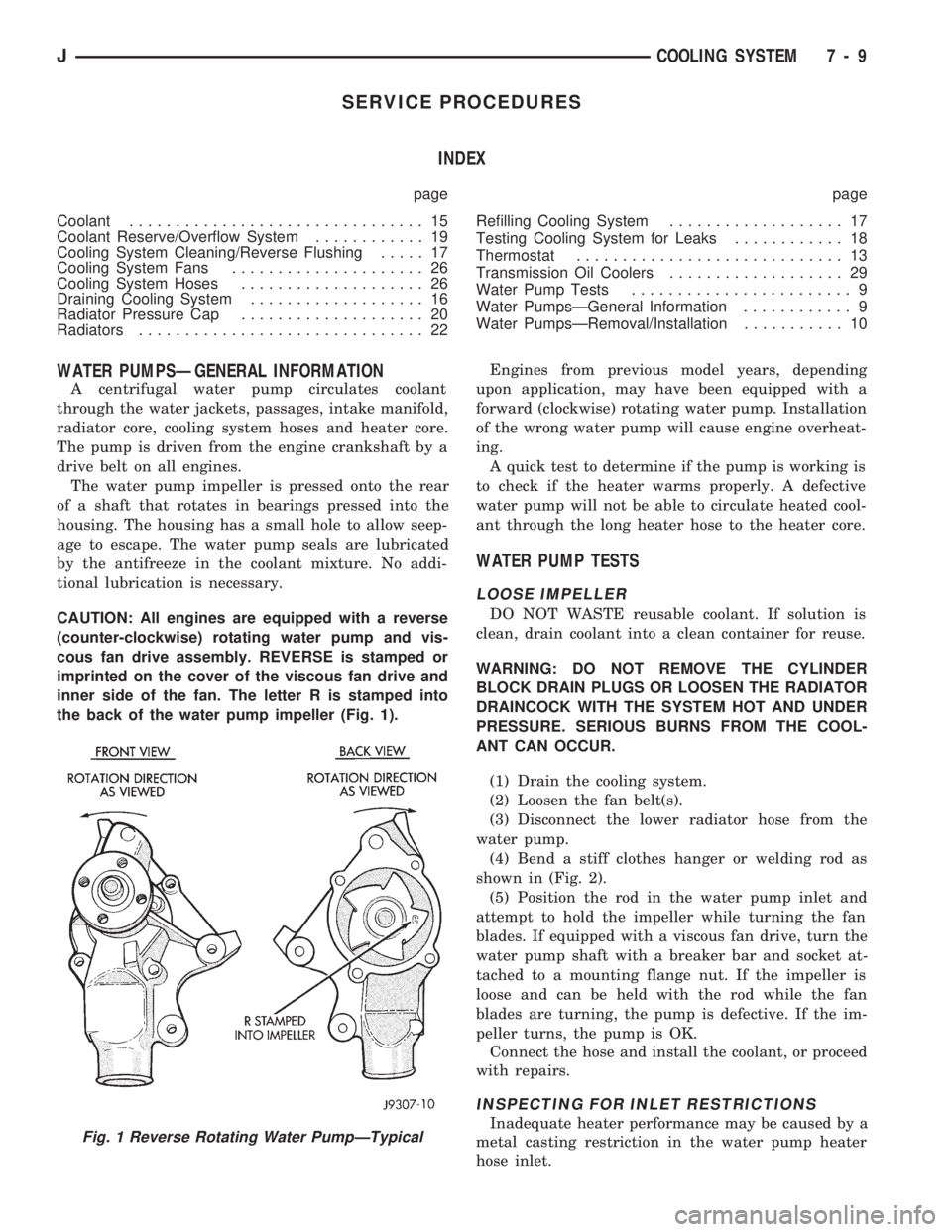
CAUTION: All engines are equipped with a reverse
(counter-clockwise) rotating water pump and vis-
cous fan drive assembly. REVERSE is stamped or
imprinted on the cover of the viscous fan drive and
inner side of the fan. The letter R is stamped into
the back of the water pump impeller (Fig. 1).Engines from previous model years, depending
upon application, may have been equipped with a
forward (clockwise) rotating water pump. Installation
of the wrong water pump will cause engine overheat-
ing.
A quick test to determine if the pump is working is
to check if the heater warms properly. A defective
water pump will not be able to circulate heated cool-
ant through the long heater hose to the heater core.
WATER PUMP TESTS
LOOSE IMPELLER
DO NOT WASTE reusable coolant. If solution is
clean, drain coolant into a clean container for reuse.
WARNING: DO NOT REMOVE THE CYLINDER
BLOCK DRAIN PLUGS OR LOOSEN THE RADIATOR
DRAINCOCK WITH THE SYSTEM HOT AND UNDER
PRESSURE. SERIOUS BURNS FROM THE COOL-
ANT CAN OCCUR.
(1) Drain the cooling system.
(2) Loosen the fan belt(s).
(3) Disconnect the lower radiator hose from the
water pump.
(4) Bend a stiff clothes hanger or welding rod as
shown in (Fig. 2).
(5) Position the rod in the water pump inlet and
attempt to hold the impeller while turning the fan
blades. If equipped with a viscous fan drive, turn the
water pump shaft with a breaker bar and socket at-
tached to a mounting flange nut. If the impeller is
loose and can be held with the rod while the fan
blades are turning, the pump is defective. If the im-
peller turns, the pump is OK.
Connect the hose and install the coolant, or proceed
with repairs.
INSPECTING FOR INLET RESTRICTIONS
Inadequate heater performance may be caused by a
metal casting restriction in the water pump heater
hose inlet.Fig. 1 Reverse Rotating Water PumpÐTypical
JCOOLING SYSTEM 7 - 9
Page 248 of 1784
CAUTION: Tightening the thermostat housing un-
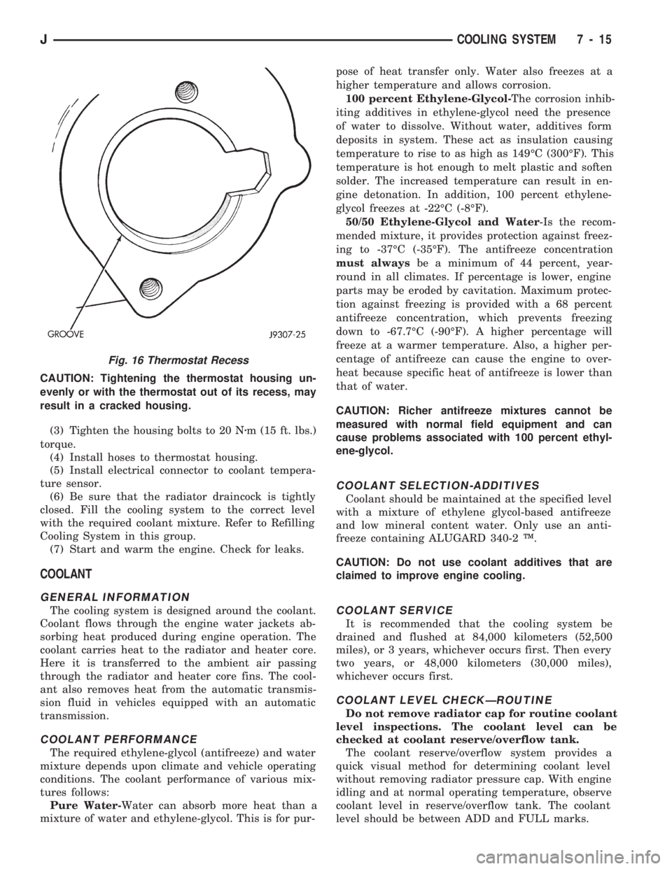
evenly or with the thermostat out of its recess, may
result in a cracked housing.
(3) Tighten the housing bolts to 20 Nzm (15 ft. lbs.)
torque.
(4) Install hoses to thermostat housing.
(5) Install electrical connector to coolant tempera-
ture sensor.
(6) Be sure that the radiator draincock is tightly
closed. Fill the cooling system to the correct level
with the required coolant mixture. Refer to Refilling
Cooling System in this group.
(7) Start and warm the engine. Check for leaks.
COOLANT
GENERAL INFORMATION
The cooling system is designed around the coolant.
Coolant flows through the engine water jackets ab-
sorbing heat produced during engine operation. The
coolant carries heat to the radiator and heater core.
Here it is transferred to the ambient air passing
through the radiator and heater core fins. The cool-
ant also removes heat from the automatic transmis-
sion fluid in vehicles equipped with an automatic
transmission.
COOLANT PERFORMANCE
The required ethylene-glycol (antifreeze) and water
mixture depends upon climate and vehicle operating
conditions. The coolant performance of various mix-
tures follows:
Pure Water-Water can absorb more heat than a
mixture of water and ethylene-glycol. This is for pur-pose of heat transfer only. Water also freezes at a
higher temperature and allows corrosion.
100 percent Ethylene-Glycol-The corrosion inhib-
iting additives in ethylene-glycol need the presence
of water to dissolve. Without water, additives form
deposits in system. These act as insulation causing
temperature to rise to as high as 149ÉC (300ÉF). This
temperature is hot enough to melt plastic and soften
solder. The increased temperature can result in en-
gine detonation. In addition, 100 percent ethylene-
glycol freezes at -22ÉC (-8ÉF).
50/50 Ethylene-Glycol and Water-Is the recom-
mended mixture, it provides protection against freez-
ing to -37ÉC (-35ÉF). The antifreeze concentration
must alwaysbe a minimum of 44 percent, year-
round in all climates. If percentage is lower, engine
parts may be eroded by cavitation. Maximum protec-
tion against freezing is provided with a 68 percent
antifreeze concentration, which prevents freezing
down to -67.7ÉC (-90ÉF). A higher percentage will
freeze at a warmer temperature. Also, a higher per-
centage of antifreeze can cause the engine to over-
heat because specific heat of antifreeze is lower than
that of water.
CAUTION: Richer antifreeze mixtures cannot be
measured with normal field equipment and can
cause problems associated with 100 percent ethyl-
ene-glycol.
COOLANT SELECTION-ADDITIVES
Coolant should be maintained at the specified level
with a mixture of ethylene glycol-based antifreeze
and low mineral content water. Only use an anti-
freeze containing ALUGARD 340-2 Ÿ.
CAUTION: Do not use coolant additives that are
claimed to improve engine cooling.
COOLANT SERVICE
It is recommended that the cooling system be
drained and flushed at 84,000 kilometers (52,500
miles), or 3 years, whichever occurs first. Then every
two years, or 48,000 kilometers (30,000 miles),
whichever occurs first.
COOLANT LEVEL CHECKÐROUTINE
Do not remove radiator cap for routine coolant
level inspections. The coolant level can be
checked at coolant reserve/overflow tank.
The coolant reserve/overflow system provides a
quick visual method for determining coolant level
without removing radiator pressure cap. With engine
idling and at normal operating temperature, observe
coolant level in reserve/overflow tank. The coolant
level should be between ADD and FULL marks.
Fig. 16 Thermostat Recess
JCOOLING SYSTEM 7 - 15
Page 249 of 1784
ADDING ADDITIONAL COOLANTÐROUTINE
Do not remove radiator cap to add coolant to
system.When adding coolant to maintain correct
level, do so at coolant reserve/overflow tank. Use a
50/50 mixture of ethylene-glycol antifreeze contain-
ing Alugard 340-2 Ÿ and low mineral content water.
Remove radiator cap only for testing or when refill-
ing system after service. Removing cap unnecessarily
can cause loss of coolant and allow air to enter sys-
tem, which produces corrosion.
COOLANT LEVEL CHECK-SERVICE
The cooling system is closed and designed to main-
tain coolant level to top of radiator.
WARNING: DO NOT OPEN RADIATOR DRAINCOCK
WITH ENGINE RUNNING OR WHILE ENGINE IS HOT
AND COOLING SYSTEM IS UNDER PRESSURE.
When vehicle servicing requires a coolant level
check in radiator, drain several ounces of coolant
from radiator drain cock. Do this while observing
coolant reserve/overflow system tank. The coolant
level in reserve/overflow tank should drop slightly. If
not, inspect for a leak between radiator and coolant
reserve/overflow system connection. Remove radiator
cap. The coolant level should be to top of radiator. If
not and if coolant level in reserve/overflow tank is at
ADD mark, check for:
²An air leak in coolant reserve/overflow tank or its
hose
²An air leak in radiator filler neck
²Leak in pressure cap seal to radiator filler neck
LOW COOLANT LEVEL-AERATION
If the coolant level in radiator drops below top of
radiator core tubes, air will enter cooling system.
Low coolant level can cause thermostat pellet to be
suspended in air instead of coolant. This will cause
thermostat to open later, which in turn causes higher
coolant temperature. Air trapped in cooling system
also reduces amount of coolant circulating in heater
core resulting in low heat output.
DEAERATION
As the engine operates, any air trapped in cooling
system gathers under the radiator cap. The next time
the engine is operated, thermal expansion of coolant
will push any trapped air past radiator cap into the
coolant reserve/overflow tank. Here it escapes to the
atmosphere into the tank. When the engine cools
down the coolant, it will be drawn from the reserve/
overflow tank into the radiator to replace any re-
moved air.
DRAINING COOLING SYSTEM
ALL MODELSÐEXCEPT XJ WITH 4.0L ENGINE
WARNING: DO NOT REMOVE THE CYLINDER
BLOCK DRAIN PLUGS OR LOOSEN THE RADIATOR
DRAINCOCK WITH SYSTEM HOT AND UNDER
PRESSURE. SERIOUS BURNS FROM COOLANT
CAN OCCUR.
DO NOT WASTE reusable coolant. If the solution
is clean, drain the coolant into a clean container for
reuse.
DO NOT remove the radiator cap when draining
the coolant from the reserve/overflow tank. Open the
radiator draincock and when the tank is empty, re-
move the radiator cap. The coolant does not have to
be removed from the tank unless the system is being
refilled with a fresh mixture.
(1) Drain the coolant from the radiator by loosen-
ing the draincock.
(2) Drain coolant from engine as follows:
(a) On 2.5L engines (all models) by removing
drain plug at left rear side of block.
(b) On 4.0L engines by removing the drain plug
or coolant temperature sensor on the left side of
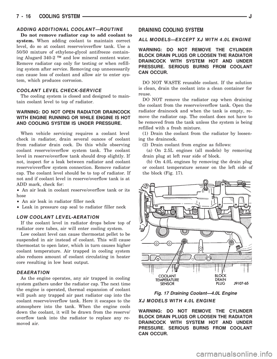
the block (Fig. 17).
XJ MODELS WITH 4.0L ENGINE
WARNING: DO NOT REMOVE THE CYLINDER
BLOCK DRAIN PLUGS OR LOOSEN THE RADIATOR
DRAINCOCK WITH SYSTEM HOT AND UNDER
PRESSURE. SERIOUS BURNS FROM COOLANT
CAN OCCUR.
Fig. 17 Draining CoolantÐ4.0L Engine
7 - 16 COOLING SYSTEMJ
Page 250 of 1784
DO NOT WASTE reusable coolant. If the solution
is clean, drain the coolant into a clean container for
reuse.
(1) Remove radiator pressure cap.
(2) For access to radiator draincock, remove radia-
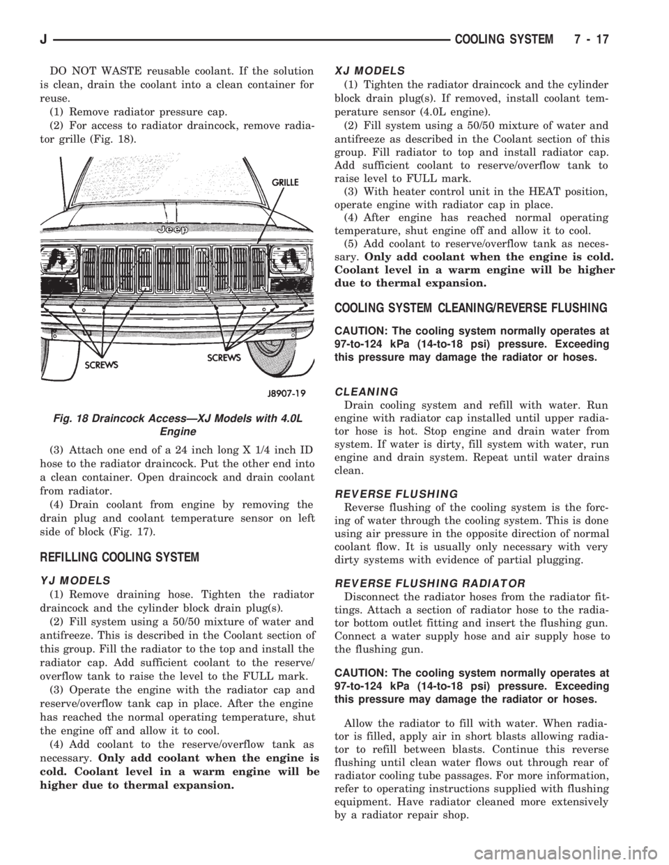
tor grille (Fig. 18).
(3) Attach one end of a 24 inch long X 1/4 inch ID
hose to the radiator draincock. Put the other end into
a clean container. Open draincock and drain coolant
from radiator.
(4) Drain coolant from engine by removing the
drain plug and coolant temperature sensor on left
side of block (Fig. 17).
REFILLING COOLING SYSTEM
YJ MODELS
(1) Remove draining hose. Tighten the radiator
draincock and the cylinder block drain plug(s).
(2) Fill system using a 50/50 mixture of water and
antifreeze. This is described in the Coolant section of
this group. Fill the radiator to the top and install the
radiator cap. Add sufficient coolant to the reserve/
overflow tank to raise the level to the FULL mark.
(3) Operate the engine with the radiator cap and
reserve/overflow tank cap in place. After the engine
has reached the normal operating temperature, shut
the engine off and allow it to cool.
(4) Add coolant to the reserve/overflow tank as
necessary.Only add coolant when the engine is
cold. Coolant level in a warm engine will be
higher due to thermal expansion.
XJ MODELS
(1) Tighten the radiator draincock and the cylinder
block drain plug(s). If removed, install coolant tem-
perature sensor (4.0L engine).
(2) Fill system using a 50/50 mixture of water and
antifreeze as described in the Coolant section of this
group. Fill radiator to top and install radiator cap.
Add sufficient coolant to reserve/overflow tank to
raise level to FULL mark.
(3) With heater control unit in the HEAT position,
operate engine with radiator cap in place.
(4) After engine has reached normal operating
temperature, shut engine off and allow it to cool.
(5) Add coolant to reserve/overflow tank as neces-
sary.Only add coolant when the engine is cold.
Coolant level in a warm engine will be higher
due to thermal expansion.
COOLING SYSTEM CLEANING/REVERSE FLUSHING
CAUTION: The cooling system normally operates at
97-to-124 kPa (14-to-18 psi) pressure. Exceeding
this pressure may damage the radiator or hoses.
CLEANING
Drain cooling system and refill with water. Run
engine with radiator cap installed until upper radia-
tor hose is hot. Stop engine and drain water from
system. If water is dirty, fill system with water, run
engine and drain system. Repeat until water drains
clean.
REVERSE FLUSHING
Reverse flushing of the cooling system is the forc-
ing of water through the cooling system. This is done
using air pressure in the opposite direction of normal
coolant flow. It is usually only necessary with very
dirty systems with evidence of partial plugging.
REVERSE FLUSHING RADIATOR
Disconnect the radiator hoses from the radiator fit-
tings. Attach a section of radiator hose to the radia-
tor bottom outlet fitting and insert the flushing gun.
Connect a water supply hose and air supply hose to
the flushing gun.
CAUTION: The cooling system normally operates at
97-to-124 kPa (14-to-18 psi) pressure. Exceeding
this pressure may damage the radiator or hoses.
Allow the radiator to fill with water. When radia-
tor is filled, apply air in short blasts allowing radia-
tor to refill between blasts. Continue this reverse
flushing until clean water flows out through rear of
radiator cooling tube passages. For more information,
refer to operating instructions supplied with flushing
equipment. Have radiator cleaned more extensively
by a radiator repair shop.
Fig. 18 Draincock AccessÐXJ Models with 4.0L
Engine
JCOOLING SYSTEM 7 - 17
Page 251 of 1784
REVERSE FLUSHING ENGINE
Drain the cooling system. Remove the thermostat
housing and thermostat. Install the thermostat hous-
ing. Disconnect the radiator upper hose from the ra-
diator and attach the flushing gun to the hose.
Disconnect the radiator lower hose from the water
pump. Attach a lead away hose to the water pump
inlet fitting.
CAUTION: On XJ models, be sure that the heater
control valve is closed (heat off). This is done to
prevent coolant flow with scale and other deposits
from entering the heater core.
Connect the water supply hose and air supply hose
to the flushing gun. Allow the engine to fill with wa-
ter. When the engine is filled, apply air in short
blasts, allowing the system to fill between air blasts.
Continue until clean water flows through the lead
away hose. For more information, refer to operating
instructions supplied with flushing equipment.
Remove the lead away hose, flushing gun, water
supply hose and air supply hose. Remove the thermo-
stat housing and install thermostat. Install the ther-
mostat housing with a replacement gasket. Refer to
Thermostat Replacement. Connect the radiator hoses.
Refill the cooling system with the correct antifreeze/
water mixture.
CHEMICAL CLEANING
In some instances, use a radiator cleaner (Mopar
Radiator Kleen or equivalent) before flushing. This
will soften scale and other deposits and aid the flush-
ing operation.
CAUTION: Be sure instructions on the container are
followed.
TESTING COOLING SYSTEM FOR LEAKS
ULTRAVIOLET LIGHT METHOD
All JeepŸ models have a leak detection additive
added to the cooling system before they leave the fac-
tory. The additive is highly visible under ultraviolet
light (black light). If the factory original coolant has
been drained, pour one ounce of additive into the
cooling system. The additive is available through the
part's department. Place the heater control unit in
HEAT position. Start and operate the engine until
the radiator upper hose is warm to the touch. Aim
the black light (tool 7138 or an equivalent), at the
components to be checked. If leaks are present, the
black light will cause the additive to glow a bright
green color.
The black light can be used along with a pressure
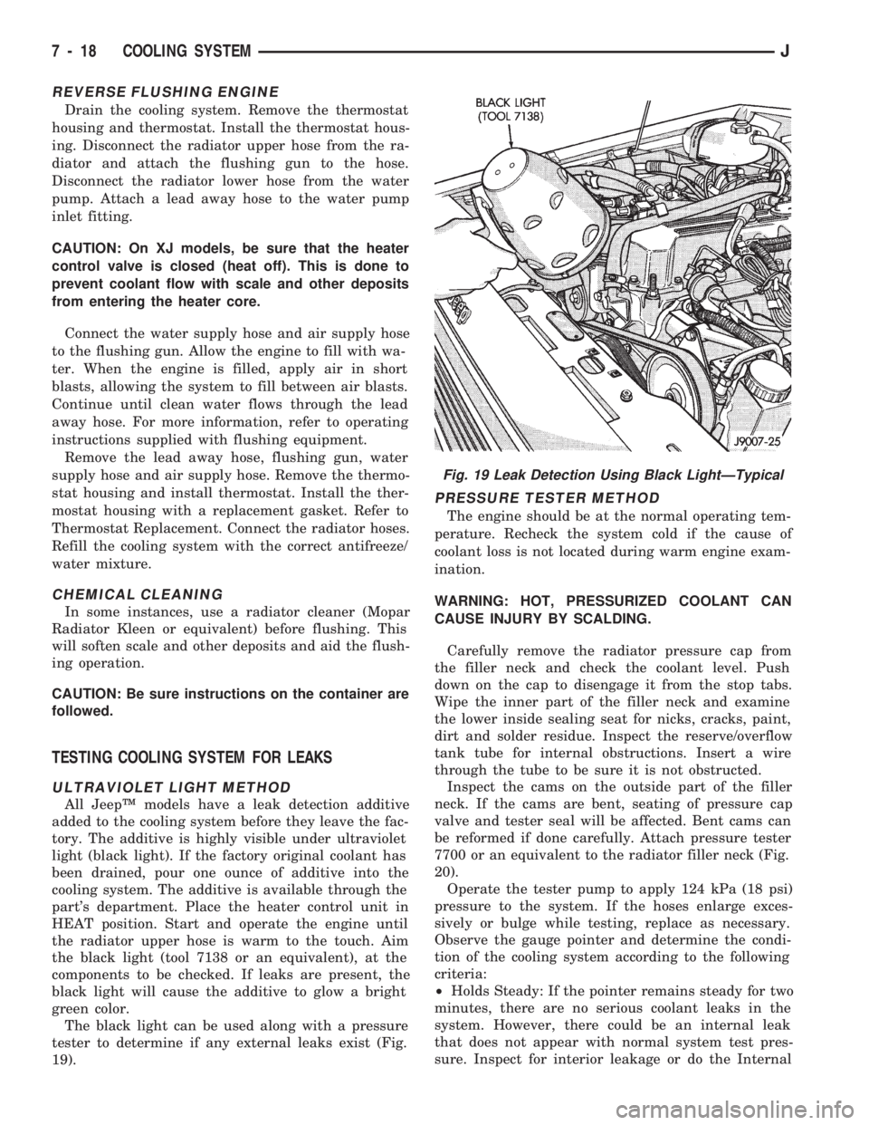
tester to determine if any external leaks exist (Fig.
19).
PRESSURE TESTER METHOD
The engine should be at the normal operating tem-
perature. Recheck the system cold if the cause of
coolant loss is not located during warm engine exam-
ination.
WARNING: HOT, PRESSURIZED COOLANT CAN
CAUSE INJURY BY SCALDING.
Carefully remove the radiator pressure cap from
the filler neck and check the coolant level. Push
down on the cap to disengage it from the stop tabs.
Wipe the inner part of the filler neck and examine
the lower inside sealing seat for nicks, cracks, paint,
dirt and solder residue. Inspect the reserve/overflow
tank tube for internal obstructions. Insert a wire
through the tube to be sure it is not obstructed.
Inspect the cams on the outside part of the filler
neck. If the cams are bent, seating of pressure cap
valve and tester seal will be affected. Bent cams can
be reformed if done carefully. Attach pressure tester
7700 or an equivalent to the radiator filler neck (Fig.
20).
Operate the tester pump to apply 124 kPa (18 psi)
pressure to the system. If the hoses enlarge exces-
sively or bulge while testing, replace as necessary.
Observe the gauge pointer and determine the condi-
tion of the cooling system according to the following
criteria:
²Holds Steady: If the pointer remains steady for two
minutes, there are no serious coolant leaks in the
system. However, there could be an internal leak
that does not appear with normal system test pres-
sure. Inspect for interior leakage or do the Internal
Fig. 19 Leak Detection Using Black LightÐTypical
7 - 18 COOLING SYSTEMJ
Page 252 of 1784

Leakage Test. Do this if it is certain that coolant is
being lost and no leaks can be detected.
²Drops Slowly: Shows a small leak or seepage is oc-
curring. Examine all connections for seepage or
slight leakage with a flashlight. Inspect the radiator,
hoses, gasket edges and heater. Seal any small leak
holes with a Sealer Lubricant or equivalent. Repair
leak holes and reinspect the system with pressure
applied.
²Drops Quickly: Shows that a serious leakage is oc-
curring. Examine the system for serious external
leakage. If no leaks are visible, inspect for internal
leakage. Large radiator leak holes should be repaired
by a reputable radiator repair shop.
INTERNAL LEAKAGE INSPECTION
Remove the oil pan drain plug and drain a small
amount of engine oil. Coolant, being heavier will
drain first, or operate engine to churn oil, then ex-
amine dipstick for water globules. Inspect the trans-
mission dipstick for water globules. Inspect the
transmission fluid cooler for leakage. Operate the en-
gine without the pressure cap on the radiator until
thermostat opens.
Attach a Pressure Tester to the filler neck. If pres-
sure builds up quickly, a leak exists as result of a
faulty cylinder head gasket or crack in the engine.
Repair as necessary.
WARNING: DO NOT ALLOW PRESSURE TO EX-
CEED 124 KPA (18 PSI). TURN THE ENGINE OFF.
TO RELEASE THE PRESSURE, ROCK THE TESTER
FROM SIDE TO SIDE. WHEN REMOVING THE
TESTER, DO NOT TURN THE TESTER MORE THAN
1/2 TURN IF THE SYSTEM IS UNDER PRESSURE.
If there is no immediate pressure increase, pump
the Pressure Tester until the indicated pressure is
within the system range. Vibration of the gauge
pointer indicates compression or combustion leakage
into the cooling system.WARNING: DO NOT DISCONNECT THE SPARK
PLUG WIRES WHILE THE ENGINE IS OPERATING.
CAUTION: Do not operate the engine with a spark
plug shorted for more than a minute. The catalytic
converter may be damaged.
Isolate the compression leak by shorting each
spark plug to the cylinder block. The gauge pointer
should stop or decrease vibration when spark plug
for leaking cylinder is shorted. This happens because
of the absence of combustion pressure.
COMBUSTION LEAKAGE TEST (WITHOUT
PRESSURE TESTER)
DO NOT WASTE reusable coolant. If the solution
is clean, drain the coolant into a clean container for
reuse.
WARNING: DO NOT REMOVE THE CYLINDER
BLOCK DRAIN PLUGS OR LOOSEN THE RADIATOR
DRAINCOCK WITH THE SYSTEM HOT AND UNDER
PRESSURE. SERIOUS BURNS FROM COOLANT
CAN OCCUR.
Drain sufficient coolant to allow for thermostat re-
moval. Refer to Thermostat Replacement. Disconnect
the water pump drive belt.
Disconnect the upper radiator hose from the ther-
mostat housing. Remove the housing and thermostat.
Install the thermostat housing.
Add coolant to the radiator to bring the level to
within 6.3 mm (1/4 in) of the top of the thermostat
housing.
CAUTION: Avoid overheating. Do not operate the
engine for an excessive period of time. Open the
draincock immediately after the test to eliminate
boil over of coolant.
Start the engine and accelerate rapidly three times
(to approximately 3000 rpm) while observing the
coolant. If internal engine combustion gases are leak-
ing into the cooling system, bubbles will appear in
the coolant. If bubbles do not appear, there is no in-
ternal combustion gas leakage.
COOLANT RESERVE/OVERFLOW SYSTEM
The system works along with the radiator pressure
cap. This is done by using thermal expansion and
contraction of the coolant to keep the coolant free of
trapped air. It provides:
²A volume for coolant expansion and contraction.
²A convenient and safe method for checking/adjust-
ing coolant level at atmospheric pressure. This is
done without removing the radiator pressure cap.
²Some reserve coolant to cover minor leaks and
evaporation or boiling losses.
Fig. 20 Pressurizing SystemÐTypical
JCOOLING SYSTEM 7 - 19