1994 JEEP CHEROKEE inflation pressure
[x] Cancel search: inflation pressurePage 3 of 1784
ROUTINE SERVICE
The following routine vehicle service is highly rec-
ommended on a monthly basis.
TIRESÐInspect the tires for unusual wear/damage
and determine if the inflation pressure is acceptable
for the vehicle load.
BATTERYÐInspect and clean the terminals.
Tighten the terminals, if necessary.
FLUIDSÐDetermine if the coolant, brake fluid,
power steering, automatic transmission, and clutch
fluid level are acceptable. Add fluid, if necessary.
LIGHTS/ELECTRICALÐTest all the electrically
operated systems in the vehicle for proper operation.
It is also recommended that the engine oil level
and the windshield washer fluid level be deter-
mined (and corrected) during each fuel fill-up.
FUEL REQUIREMENTS
All Jeeptengines require the use of unleaded gas-
oline. In addition, the fuel must have a minimum oc-
tane rating of 87.
CAUTION: UNLEADED FUEL ONLY must be used in
vehicles equipped with a catalyst emission control
system. All vehicles have reminders printed on the
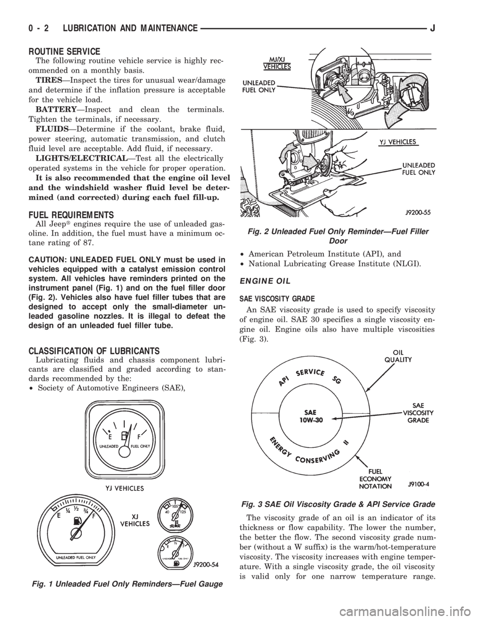
instrument panel (Fig. 1) and on the fuel filler door
(Fig. 2). Vehicles also have fuel filler tubes that are
designed to accept only the small-diameter un-
leaded gasoline nozzles. It is illegal to defeat the
design of an unleaded fuel filler tube.
CLASSIFICATION OF LUBRICANTS
Lubricating fluids and chassis component lubri-
cants are classified and graded according to stan-
dards recommended by the:
²Society of Automotive Engineers (SAE),²American Petroleum Institute (API), and
²National Lubricating Grease Institute (NLGI).
ENGINE OIL
SAE VISCOSITY GRADE
An SAE viscosity grade is used to specify viscosity
of engine oil. SAE 30 specifies a single viscosity en-
gine oil. Engine oils also have multiple viscosities
(Fig. 3).
The viscosity grade of an oil is an indicator of its
thickness or flow capability. The lower the number,
the better the flow. The second viscosity grade num-
ber (without a W suffix) is the warm/hot-temperature
viscosity. The viscosity increases with engine temper-
ature. With a single viscosity grade, the oil viscosity
is valid only for one narrow temperature range.
Fig. 1 Unleaded Fuel Only RemindersÐFuel Gauge
Fig. 2 Unleaded Fuel Only ReminderÐFuel Filler
Door
Fig. 3 SAE Oil Viscosity Grade & API Service Grade
0 - 2 LUBRICATION AND MAINTENANCEJ
Page 35 of 1784
(6) Inspect the disc brake caliper dust boot for cor-
rect installation, damage/tears and indications of
brake fluid leakage. Inspect the bushings and pins
for corrosion, tears and a binding condition.
(7) Pull the rear wheel cylinder dust boot back to
expose the wheel cylinder housing and inspect for
fluid leaks. Inspect the pistons and cylinder bores for
proper appearance.
(8) Inspect the brake differential warning valve
and housing for indications of leakage, kinked hoses
and loose fittings.
PARK BRAKE
(1) As applicable, engage the park brake lever or
pedal and then release it.
(2) If the park brake is functioning normally, test
it for smooth operation and vehicle-holding capabil-
ity.
(3) Inspect the park brake cables for kinks, fraying
and a binding condition.
(4) With the park brake released, the rear wheels
should rotate without restriction. Adjust the park
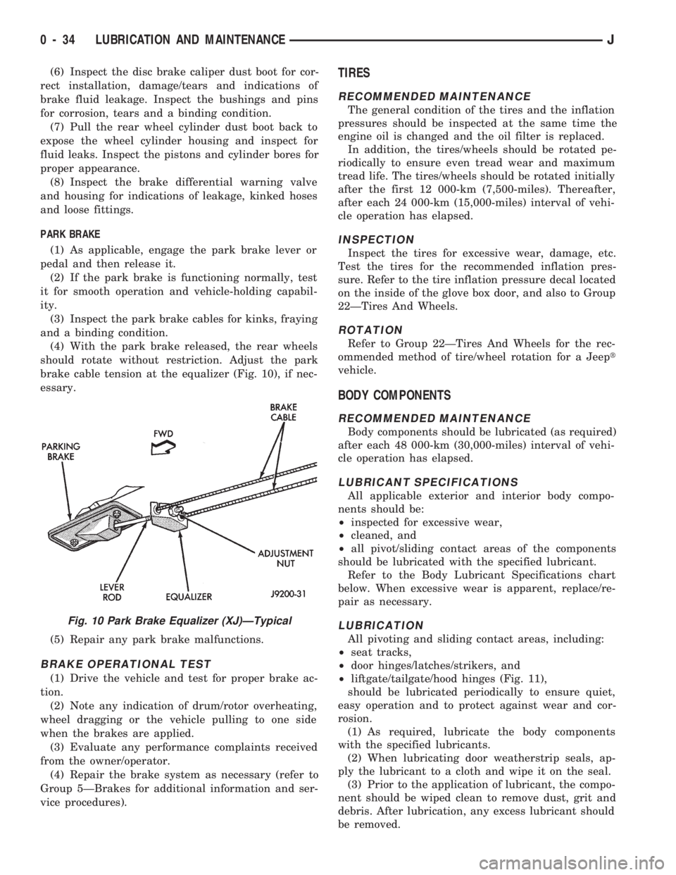
brake cable tension at the equalizer (Fig. 10), if nec-
essary.
(5) Repair any park brake malfunctions.
BRAKE OPERATIONAL TEST
(1) Drive the vehicle and test for proper brake ac-
tion.
(2) Note any indication of drum/rotor overheating,
wheel dragging or the vehicle pulling to one side
when the brakes are applied.
(3) Evaluate any performance complaints received
from the owner/operator.
(4) Repair the brake system as necessary (refer to
Group 5ÐBrakes for additional information and ser-
vice procedures).
TIRES
RECOMMENDED MAINTENANCE
The general condition of the tires and the inflation
pressures should be inspected at the same time the
engine oil is changed and the oil filter is replaced.
In addition, the tires/wheels should be rotated pe-
riodically to ensure even tread wear and maximum
tread life. The tires/wheels should be rotated initially
after the first 12 000-km (7,500-miles). Thereafter,
after each 24 000-km (15,000-miles) interval of vehi-
cle operation has elapsed.
INSPECTION
Inspect the tires for excessive wear, damage, etc.
Test the tires for the recommended inflation pres-
sure. Refer to the tire inflation pressure decal located
on the inside of the glove box door, and also to Group
22ÐTires And Wheels.
ROTATION
Refer to Group 22ÐTires And Wheels for the rec-
ommended method of tire/wheel rotation for a Jeept
vehicle.
BODY COMPONENTS
RECOMMENDED MAINTENANCE
Body components should be lubricated (as required)
after each 48 000-km (30,000-miles) interval of vehi-
cle operation has elapsed.
LUBRICANT SPECIFICATIONS
All applicable exterior and interior body compo-
nents should be:
²inspected for excessive wear,
²cleaned, and
²all pivot/sliding contact areas of the components
should be lubricated with the specified lubricant.
Refer to the Body Lubricant Specifications chart
below. When excessive wear is apparent, replace/re-
pair as necessary.
LUBRICATION
All pivoting and sliding contact areas, including:
²seat tracks,
²door hinges/latches/strikers, and
²liftgate/tailgate/hood hinges (Fig. 11),
should be lubricated periodically to ensure quiet,
easy operation and to protect against wear and cor-
rosion.
(1) As required, lubricate the body components
with the specified lubricants.
(2) When lubricating door weatherstrip seals, ap-
ply the lubricant to a cloth and wipe it on the seal.
(3) Prior to the application of lubricant, the compo-
nent should be wiped clean to remove dust, grit and
debris. After lubrication, any excess lubricant should
be removed.
Fig. 10 Park Brake Equalizer (XJ)ÐTypical
0 - 34 LUBRICATION AND MAINTENANCEJ
Page 951 of 1784

CONSTRUCTION
The frame is constructed of high-strength channel
steel siderails and crossmembers. The crossmembers
join the siderails and retain them in alignment in re-
lation to each other. This provides resistance to
frame twists and strains.
FRAME ALIGNMENT
INCORRECT ALIGNMENT
Incorrect frame alignment is usually a result of:
²collision impact, or
²the vehicle being operated with excessive loads, or
²loads not positioned in a properly distributed man-
ner on the vehicle.
A mis-aligned frame will affect front axle and/or
rear axle alignment. It can cause excessive wear and
mechanical failures in the powertrain. Window glass
cracks and door opening/closing problems. Vehicle
performance can also be impaired.
RE-ALIGNMENT
With collision damage, it is important that the ex-
istence of any frame alignment damage be deter-
mined. If necessary, the frame should be correctly re-
aligned. Refer to the reference dimensions listed on
frame alignment dimension chart (Fig. 4).
FRAME INSPECTION/MEASUREMENTS
INSPECTION
Before proceeding with measurements, inspect all
components for visible damage and other metal dam-
age. Also, inspect all connections for loose and miss-
ing hardware.
All damaged areas must be repaired and/or the
components replaced, as necessary.
MEASUREMENTS
Measure the frame for mis-alignment with the
body attached to the frame. Figure 4 provides the
alignment reference dimensions. The following infor-
mation applies to all measurements.
(1) Place the vehicle on a level surface.
(2) If the vehicle is loaded, ensure that the vehicle
weight plus the payload does not exceed the gross ve-
hicle weight rating. Also, ensure that the load is dis-
tributed in the vehicle as evenly as possible.
(3) Measure the tire inflation pressures and adjust
the pressure, if necessary.
HORIZONTAL OR DIAGONAL FRAME MEASUREMENTS
Determine the frame horizontal non-square devia-
tion(s) according to the following procedure.
(1) Select several reference points along one frame
siderail, preferably at the crossmember junctions.(2) Transfer these reference points to the surface/
floor with a plumb bob. Paper sheets can be attached
to the surface below the reference points for better
measurement accuracy.
(3) Locate the reference points on the other frame
siderail and transfer them to the surface/floor with
the same procedure as above.
(4) Move the vehicle away and measure between
all the reference points diagonally from and parallel
to the siderails (Fig. 5). The measurements should
not differ by more than 6 mm (1/4 in).
(5) Measure the distance between the two front
reference points and the distance between the two
rear reference points. Divide each distance in half
and indicate the two half-way points on the surface/
floor. Designate the front point as ``1'' and the rear
point as ``2'' (Fig. 5).
(6) Place a chalk-line between points 1 and 2 and
``snap'' the string.
(7) Determine how close the center line is to the
diagonal intersection points A, B, C, D, E, and F in
Figure 5.
(8) The reference marks on the surface/floor will
provide an illustrated indication of the degree of
frame misalignment.
(9) A reference point transferred from one frame
siderail may be 3 mm (1/8 in) ahead or behind the
reference point from the opposite siderail.
(10) Frame bow to the side should not exceed 3
mm per 2,540 mm (1/8 inch per 100 inches) in
length.
(11) The overall width of the frame should not
vary more than 3 mm (1/8 in) from reference point-
to-reference point.
(12) Repeat steps (1) through (11) after straighten-
ing the frame to evaluate the effectiveness.
TWIST AND PARALLEL FRAME MEASUREMENTS
Determine the amount of frame twist and siderail
deviation according to the following procedure.
(1) Mark the vertical measurement reference
points under the frame siderails at 305-mm (12-in)
intervals starting at the rear frame crossmember.
(2) Measure the vertical distance up from a level
surface to each reference point located under the left
and right frame siderails.
(3) The distance to a reference point under one
frame siderail should be 3 mm (1/8 in) greater or less
than the point under the opposite siderail.
(4) Plot the measured vertical distances to scale on
a sheet of graph paper. Plot the distances so that the
frame siderails are located adjacent to each other.
Join the vertical distance points.
13 - 10 FRAME AND BUMPERSJ
Page 1444 of 1784
WHEELS AND TIRES
CONTENTS
page page
SPECIFICATIONS....................... 11
TIRES................................. 1VEHICLE VIBRATION..................... 9
WHEELS............................... 6
TIRES
INDEX
page page
Cleaning of Tires.......................... 2
General Information........................ 1
Pressure Gauges......................... 2
Repairing Leaks.......................... 3
Replacement Tires........................ 2Rotation................................ 3
Tire Inflation Pressures..................... 2
Tire Noise or Vibration..................... 4
Tire Wear Patterns........................ 4
Tread Wear Indicators...................... 3
GENERAL INFORMATION
Tires are designed for each specific vehicle. They
provide the best overall performance for normal op-
eration. The ride and handling characteristics match
the vehicle's requirements. With proper care they
will give excellent reliability, traction, skid resis-
tance, and tread life. These tires have specific load
carrying capacities. When correctly inflated, they
will operate properly.
Tires used in cool climates, and with light loads
will have a longer life than tires used in hot climates
with heavy loads. Abrasive road surfaces will accel-
erate tire wear.
Driving habits have more effect on tire life than
any other factor. Careful drivers will obtain much
greater mileage than careless drivers.
Driving habits that shorten the life of any tire;
²Rapid acceleration and deceleration
²Severe application of brakes
²High-speed driving
²Taking turns at excessive speeds
²Striking curbs and other obstacles
It is very important to follow the tire rotation in-
terval
IDENTIFICATION
Tire type, size, aspect ratio and speed rating are
encoded in the letters and numbers imprinted on the
side wall of the tire. Refer to the chart to decipher
the tire identification code (Fig. 1).
Performance tires will have a speed rating letter
after the aspect ratio number. The speed rating isnot always printed on the tire sidewall. The letterS
indicates that the tire is speed rated up to 112 mph.
²Qup to 100 mph
²Tup to 118 mph
²Uup to 124 mph
²Hup to 130 mph
²Vup to 149 mph
²Zmore than 149 mph (consult the tire manufac-
turer for the specific speed rating)
An All Season type tire will have eitherM+S,M
&SorMÐS(indicating mud and snow traction) im-
printed on the side wall.
RADIAL-PLY TIRES
Radial-ply tires improve handling, tread life, ride
quality and decrease rolling resistance.
Radial-ply tires must always be used in sets of
four. Under no circumstances should they be used on
the front only. They may be mixed with temporary
spare tires when necessary, but reduced speeds are
recommended.
Radial-ply tires have the same load-carrying capac-
ity as other types of tires of the same size. They use
the same recommended inflation pressures.
SPARE TIRE (TEMPORARY)
The compact spare tire is designed for emergency
use only. The original tire should be repaired and re-
installed at the first opportunity. Refer to Owner's
Manual for complete details.
JWHEELS AND TIRES 22 - 1
Page 1445 of 1784
TIRE CHAINS
Tire snow chains may be used on certain models.
Refer to Owner's Manual for more information.
CLEANING OF TIRES
Steam cleaning may be used for cleaning.
DO NOT use gasoline or wire brush for cleaning.
DO NOT use mineral oil or an oil-based solvent.
PRESSURE GAUGES
High-quality, dial-type, air-pressure gauges are
recommended. After checking with the gauge, re-
place valve cap and finger tight.
TIRE INFLATION PRESSURES
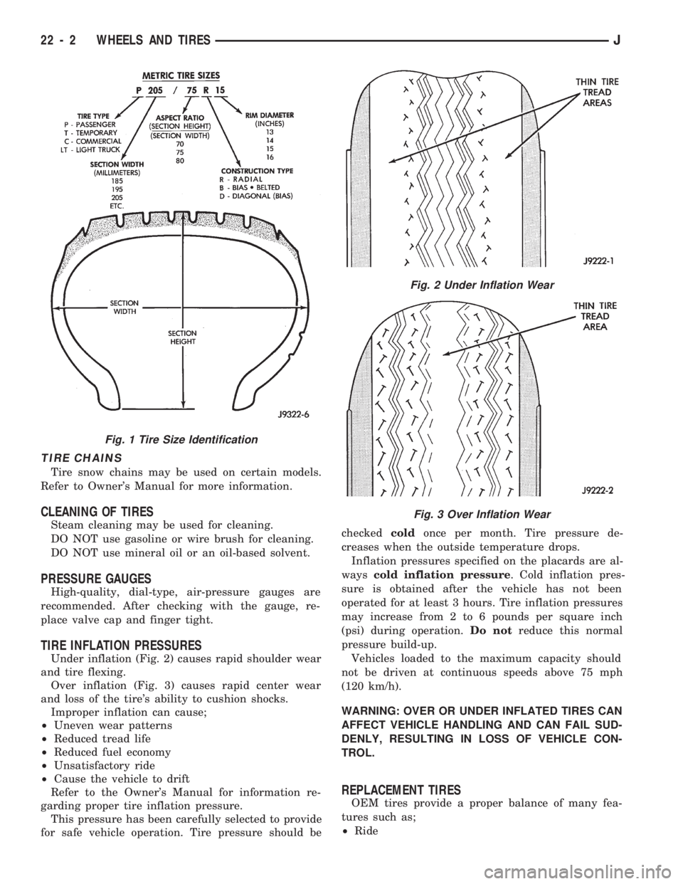
Under inflation (Fig. 2) causes rapid shoulder wear
and tire flexing.
Over inflation (Fig. 3) causes rapid center wear
and loss of the tire's ability to cushion shocks.
Improper inflation can cause;
²Uneven wear patterns
²Reduced tread life
²Reduced fuel economy
²Unsatisfactory ride
²Cause the vehicle to drift
Refer to the Owner's Manual for information re-
garding proper tire inflation pressure.
This pressure has been carefully selected to provide
for safe vehicle operation. Tire pressure should becheckedcoldonce per month. Tire pressure de-
creases when the outside temperature drops.
Inflation pressures specified on the placards are al-
wayscold inflation pressure. Cold inflation pres-
sure is obtained after the vehicle has not been
operated for at least 3 hours. Tire inflation pressures
may increase from 2 to 6 pounds per square inch
(psi) during operation.Do notreduce this normal
pressure build-up.
Vehicles loaded to the maximum capacity should
not be driven at continuous speeds above 75 mph
(120 km/h).
WARNING: OVER OR UNDER INFLATED TIRES CAN
AFFECT VEHICLE HANDLING AND CAN FAIL SUD-
DENLY, RESULTING IN LOSS OF VEHICLE CON-
TROL.
REPLACEMENT TIRES
OEM tires provide a proper balance of many fea-
tures such as;
²Ride
Fig. 1 Tire Size Identification
Fig. 2 Under Inflation Wear
Fig. 3 Over Inflation Wear
22 - 2 WHEELS AND TIRESJ
Page 1735 of 1784
INTRODUCTION
CONTENTS
page page
DESIGNATIONS, LABELS/PLATES, CODES
AND DIMENSIONS..................... 1SPECIFICATIONS........................ 8
DESIGNATIONS, LABELS/PLATES, CODES AND DIMENSIONS
INDEX
page page
Engine and Transmission/Transfer Case Identification.3
International Vehicle Control and Display Symbols . 3
Major Component Identification............... 3
Tire Inflation Pressure Label................. 3
Vehicle Code Plate........................ 2Vehicle Designations....................... 1
Vehicle Dimension Data.................... 3
Vehicle Identification Number (VIN) Plate....... 1
Vehicle Load Data........................ 3
Vehicle Safety Certification Label............. 1
VEHICLE DESIGNATIONS
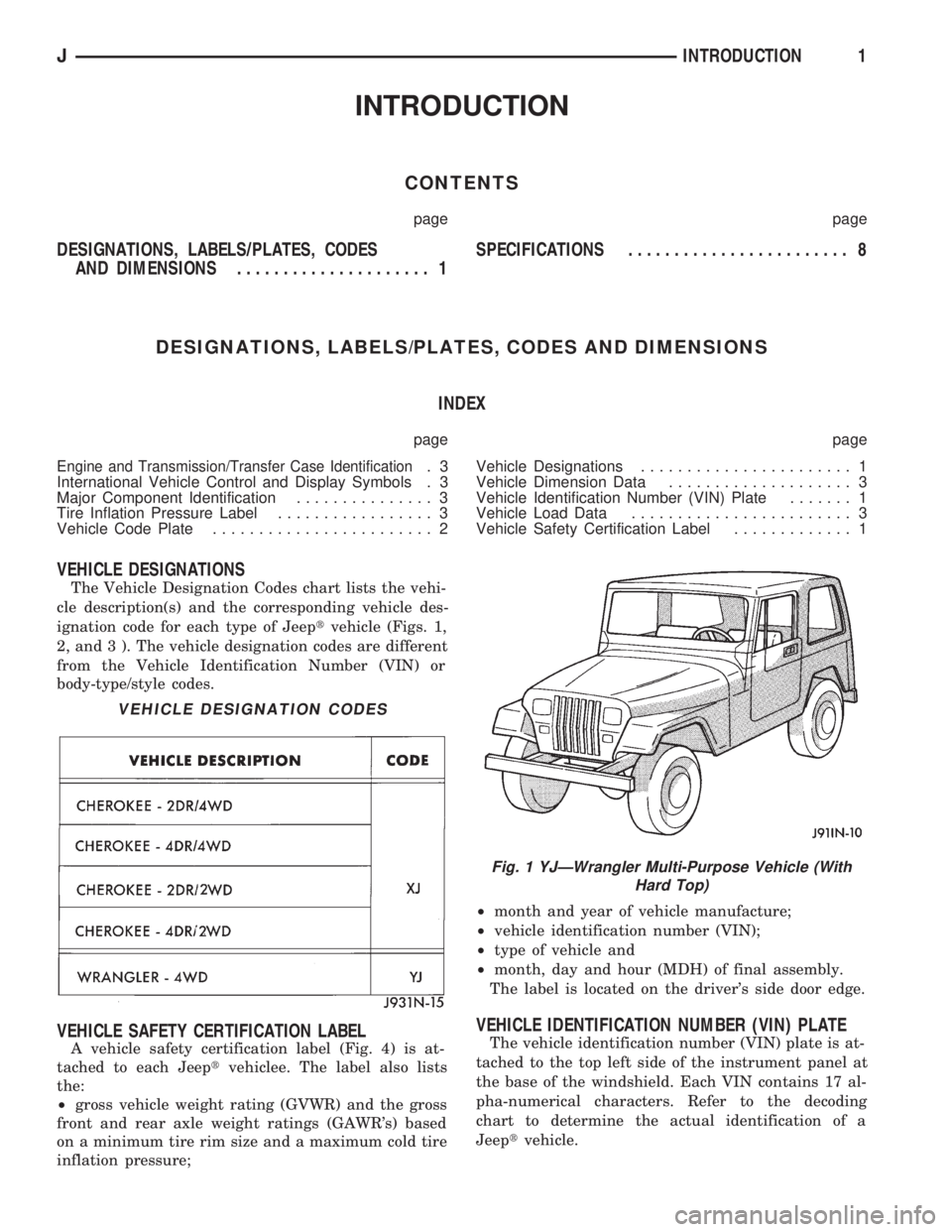
The Vehicle Designation Codes chart lists the vehi-
cle description(s) and the corresponding vehicle des-
ignation code for each type of Jeeptvehicle (Figs. 1,
2, and 3 ). The vehicle designation codes are different
from the Vehicle Identification Number (VIN) or
body-type/style codes.
VEHICLE SAFETY CERTIFICATION LABEL
A vehicle safety certification label (Fig. 4) is at-
tached to each Jeeptvehiclee. The label also lists
the:
²gross vehicle weight rating (GVWR) and the gross
front and rear axle weight ratings (GAWR's) based
on a minimum tire rim size and a maximum cold tire
inflation pressure;²month and year of vehicle manufacture;
²vehicle identification number (VIN);
²type of vehicle and
²month, day and hour (MDH) of final assembly.
The label is located on the driver's side door edge.
VEHICLE IDENTIFICATION NUMBER (VIN) PLATE
The vehicle identification number (VIN) plate is at-
tached to the top left side of the instrument panel at
the base of the windshield. Each VIN contains 17 al-
pha-numerical characters. Refer to the decoding
chart to determine the actual identification of a
Jeeptvehicle.
VEHICLE DESIGNATION CODES
Fig. 1 YJÐWrangler Multi-Purpose Vehicle (With
Hard Top)
JINTRODUCTION1
Page 1737 of 1784
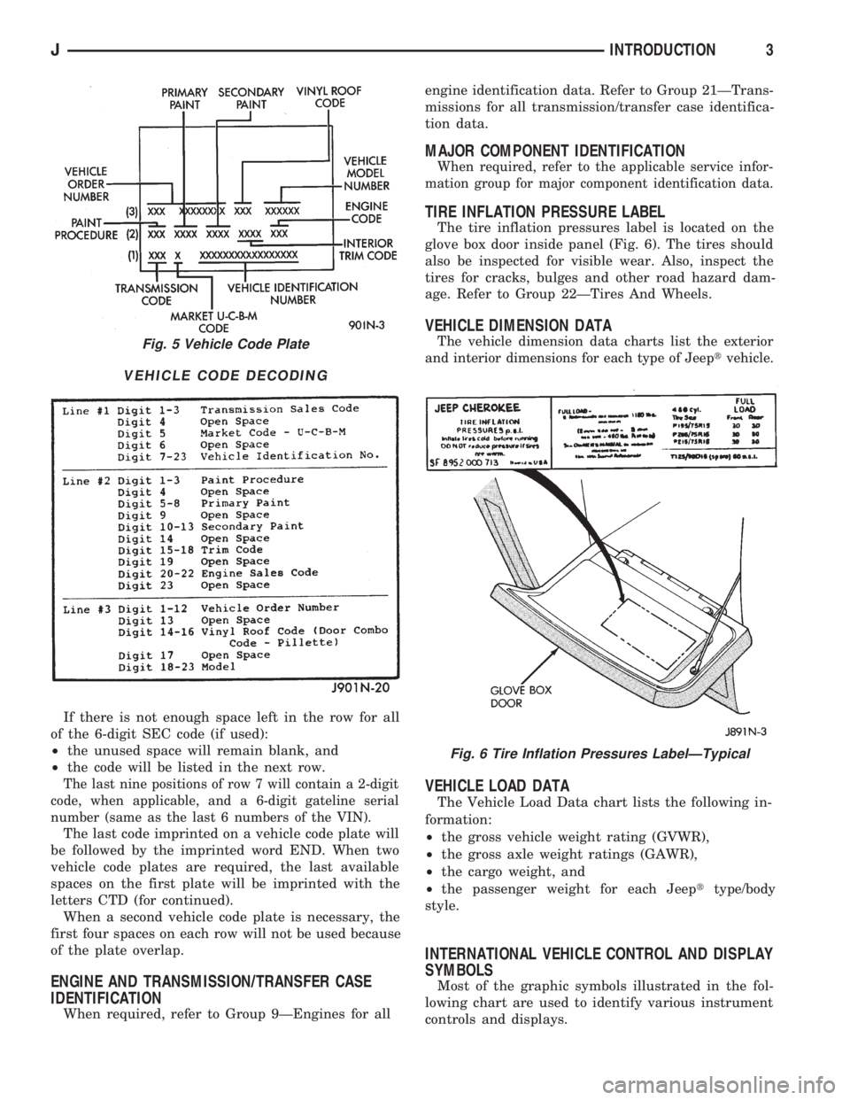
If there is not enough space left in the row for all
of the 6-digit SEC code (if used):
²the unused space will remain blank, and
²the code will be listed in the next row.
The last nine positions of row 7 will contain a 2-digit
code, when applicable, and a 6-digit gateline serial
number (same as the last 6 numbers of the VIN).
The last code imprinted on a vehicle code plate will
be followed by the imprinted word END. When two
vehicle code plates are required, the last available
spaces on the first plate will be imprinted with the
letters CTD (for continued).
When a second vehicle code plate is necessary, the
first four spaces on each row will not be used because
of the plate overlap.
ENGINE AND TRANSMISSION/TRANSFER CASE
IDENTIFICATION
When required, refer to Group 9ÐEngines for allengine identification data. Refer to Group 21ÐTrans-
missions for all transmission/transfer case identifica-
tion data.
MAJOR COMPONENT IDENTIFICATION
When required, refer to the applicable service infor-
mation group for major component identification data.
TIRE INFLATION PRESSURE LABEL
The tire inflation pressures label is located on the
glove box door inside panel (Fig. 6). The tires should
also be inspected for visible wear. Also, inspect the
tires for cracks, bulges and other road hazard dam-
age. Refer to Group 22ÐTires And Wheels.
VEHICLE DIMENSION DATA
The vehicle dimension data charts list the exterior
and interior dimensions for each type of Jeeptvehicle.
VEHICLE LOAD DATA
The Vehicle Load Data chart lists the following in-
formation:
²the gross vehicle weight rating (GVWR),
²the gross axle weight ratings (GAWR),
²the cargo weight, and
²the passenger weight for each Jeepttype/body
style.
INTERNATIONAL VEHICLE CONTROL AND DISPLAY
SYMBOLS
Most of the graphic symbols illustrated in the fol-
lowing chart are used to identify various instrument
controls and displays.
Fig. 5 Vehicle Code Plate
VEHICLE CODE DECODING
Fig. 6 Tire Inflation Pressures LabelÐTypical
JINTRODUCTION3
Page 1756 of 1784
ILLUMINATION LAMPS, INSTRUMENT
PANEL.............................8E-16
ILLUMINATION, RADIO/CLOCK.............8E-4
ILLUMINATION RELAY, RADIO.............8F-3
INDEX, GROUP; ELECTRICAL..............8A-1
INDEX, GROUP; INSTRUMENT PANEL
AND GAUGES........................8E-1
INDEX; WIRING DIAGRAMS XJ..........8W-149
INDEX; WIRING DIAGRAMS XJ-RHD.....8W-271
INDEX; WIRING DIAGRAMS YJ...........8W-73
INDEXES, WIRING DIAGRAM SHEETS......8W-1
INDICATOR, 4WD......................8E-22
INDICATOR, ANTI-LOCK..................8E-4
INDICATOR (BASE CLUSTER ONLY),
OPERATIONAL CHECK WITH BATTERY....8A-14
INDICATOR BEZEL REPLACEMENT.........8E-17
INDICATOR (CHECK ENGINE) LAMP FOR
DIAGNOSTIC TROUBLE CODES..........8A-19
INDICATOR INOPERATIVE, 4WD............8E-4
INDICATOR INOPERATIVE, BRAKE..........8E-4
INDICATOR INOPERATIVE, COOLANT
TEMPERATURE.......................8E-3
INDICATOR INOPERATIVE, LOW WASHER....8E-4
INDICATOR INOPERATIVE, OIL
PRESSURE..........................8E-3
INDICATOR INOPERATIVE, UPSHIFT........8E-4
INDICATOR LAMP, 4WD..................8E-2
INDICATOR LAMP, ANTI-LOCK BRAKE
SYSTEM (ABS).......................8E-2
INDICATOR LAMP, BRAKE; INSTRUMENT
PANEL AND GAUGESÐXJ...............8E-2
INDICATOR LAMP, BRAKE; INSTRUMENT
PANEL AND GAUGESÐYJ..............8E-16
INDICATOR LAMP (CHECK ENGINE),
MALFUNCTION; INSTRUMENT PANEL
AND GAUGESÐXJ................8E-2,8E-4
INDICATOR LAMP (CHECK ENGINE),
MALFUNCTION; INSTRUMENT PANEL
AND GAUGESÐYJ...................8E-16
INDICATOR LAMP, COOLANT
TEMPERATURE.......................8E-1
INDICATOR LAMPÐPCM OUTPUT,
MALFUNCTION......................14-26
INDICATOR LAMP, UPSHIFT; INSTRUMENT
PANEL AND GAUGESÐXJ...............8E-2
INDICATOR LAMP, UPSHIFT; INSTRUMENT
PANEL AND GAUGESÐYJ..............8E-16
INDICATOR LAMPS....................8E-14
INDICATOR, OIL PRESSURE...............8E-1
INDICATORÐPCM OUTPUT, SHIFT........14-26
INDICATOR REPLACEMENTÐGEAR
SELECTOR...........................8E-6
INDICATOR, SEAT BELT..................8E-4
INDICATOR (SRI) LAMP, SERVICE
REMINDER..........................25-1
INDICATORS INOPERATIVE, GAUGES.......8E-3
INDICATORS, TREAD WEAR...............22-3
INFLATION PRESSURE LABEL, TIRE.....INTRO.-3
INFLATION PRESSURES, TIRE.............22-2
INITIALIZATION, SYSTEM POWER-UP.......5-43
INJECTION (MFI)ÐCOMPONENT
DESCRIPTION/SYSTEM OPERATION,
MULTI-PORT FUEL...................14-17
INJECTION (MFI)ÐCOMPONENT
REMOVAL/INSTALLATION, MULTI-PORT
FUEL..............................14-54
INJECTION (MFI)ÐGENERAL DIAGNOSIS,
MULTI-PORT FUEL...................14-32
INJECTOR DIAGNOSISÐVEHICLE RUNS
ROUGH AND/OR HAS A MISS
...........14-49
INJECTOR, FUEL
.......................14-55
INJECTOR TEST
.......................14-48
INJECTORSÐPCM OUTPUT, FUEL
.........14-25
INNER AXLE SHAFT OIL SEAL
REPLACEMENT
.......................2-33
INNER SCUFF PLATE/COWL SIDE TRIM
PANELÐXJ VEHICLES, FRONT
.........23-114
INNER SPLASH SHIELDS, FENDER
.......23-147
INOPERATIVE, 4WD INDICATOR
............8E-4
INOPERATIVE, ALL GAUGES
.............8E-22
INOPERATIVE, BRAKE INDICATOR
..........8E-4
INOPERATIVE, COOLANT TEMPERATURE
GAUGE
..............................8E-3
INOPERATIVE, COOLANT TEMPERATURE
INDICATOR
..........................8E-3INOPERATIVE, DIAGNOSINGÐTURN
SIGNAL.............................8J-2
INOPERATIVE, DIAGNOSISÐHAZARD
LAMPS..........................8J-1,8J-2
INOPERATIVE, DIAGNOSISÐTURN
SIGNAL.............................8J-1
INOPERATIVE, FUEL GAUGE...............8E-3
INOPERATIVE, GAUGES AND INDICATORS....8E-3
INOPERATIVE, LOW FUEL WARNING........8E-4
INOPERATIVE, LOW WASHER INDICATOR....8E-4
INOPERATIVE, OIL PRESSURE GAUGE......8E-3
INOPERATIVE, OIL PRESSURE
INDICATOR..........................8E-3
INOPERATIVE, ONE GAUGE..............8E-22
INOPERATIVE, SPEEDOMETER/
ODOMETER..........................8E-3
INOPERATIVE, TACHOMETER..............8E-3
INOPERATIVE, UPSHIFT INDICATOR........8E-4
INOPERATIVE, VOLTMETER...............8E-3
INPUT, AIR CONDITIONING (A/C)
CONTROLSÐPCM....................14-19
INPUT, AUTOMATIC SHUT DOWN (ASD)
SENSEÐPCM.......................14-19
INPUT, BATTERY VOLTAGEÐPCM.........14-19
INPUT, BRAKE SWITCHÐPCM............14-20
INPUT, CAMSHAFT POSITION SENSORÐ
PCM...............................14-20
INPUT, CRANKSHAFT POSITION
SENSORÐPCM......................14-20
INPUT, DATA LINK CONNECTORÐPCM.....14-20
INPUT, ENGINE COOLANT TEMPERATURE
SENSORÐPCM......................14-21
INPUT, EXTENDED IDLE SWITCHÐPCM....14-21
INPUT, IGNITION CIRCUIT SENSEÐPCM....14-21
INPUT, INTAKE AIR TEMPERATURE
SENSORÐPCM......................14-20
INPUT, LOSS OF SENSOR.................5-3
INPUT, MANIFOLD ABSOLUTE
PRESSURE (MAP) SENSORÐPCM.......14-21
INPUT, OXYGEN (O2S) SENSORÐPCM.....14-22
INPUT, PARK/NEUTRAL SWITCHÐPCM.....14-22
INPUT, POWER STEERING PRESSURE
SWITCHÐPCM......................14-22
INPUT, SCI RECEIVEÐPCM..............14-22
INPUT, SENSOR RETURNÐPCM..........14-23
INPUT SIGNALS, WHEEL/TIRE SIZE..........5-3
INPUT, SPEED CONTROLÐPCM..........14-23
INPUT, THROTTLE POSITION SENSOR
(TPS)ÐPCM........................14-23
INPUT, VEHICLE SPEED SENSORÐPCM....14-23
INSERTÐXJ VEHICLES, QUARTER
WINDOW GLASS/REAR QUARTER
PLASTIC...........................23-80
INSIDE LATCH RELEASE AND LOCK
RODS, DOOR........................23-57
INSIDE RELEASE AND LOCK HANDLE,
FULL-METAL DOOR LATCH............23-175
INSPECTION AND ADJUSTMENT,
PRELIMINARY......................21-167
INSPECTION AND DIAGNOSIS CHARTS.......6-4
INSPECTION, CALIPER CLEANING..........5-28
INSPECTION, CLEANING....21-13,21-204,21-305
INSPECTION, COMPONENT................5-8
INSPECTION, GEAR CLEANING...........19-40
INSPECTION, PRE-ALIGNMENT.............2-6
INSPECTION, TORQUE CONVERTER
STATOR CLUTCH....................21-189
INSPECTION, TRANSMISSION CASE
CLEANING.........................21-118
INSPECTION, VALVE BODY DISASSEMBLY
. . 21-138
INSPECTION, VISUAL
...................14-32
INSPECTION/MEASUREMENTS, FRAME
.....13-10
INSPECTIONS, STARTER SYSTEM
DIAGNOSTIC
.........................8A-9
INSTALLATION, 30RH/32RH
TRANSMISSION REMOVAL
............21-108
INSTALLATION, ACCELERATION SENSOR
....5-52
INSTALLATION, AW-4 TRANSMISSION
REMOVAL AND
.....................21-189
INSTALLATIONÐAX 15, TRANSMISSION
....21-35
INSTALLATION, BRAKE PEDAL
.............5-66
INSTALLATION, BRAKELIGHT SWITCH
.......5-66
INSTALLATION, CALIPER
.................5-30
INSTALLATION, CLUTCH COVER AND
DISC
...............................6-10INSTALLATION, CLUTCH HYDRAULIC
LINKAGE............................6-12
INSTALLATION, CLUTCH PEDAL............6-15
INSTALLATION, DIFFERENTIAL; FRONT
SUSPENSION AND AXLE................2-43
INSTALLATION, DIFFERENTIAL; REAR
SUSPENSION AND AXLES...............3-24
INSTALLATION, DISC BRAKESHOE..........5-26
INSTALLATION, DRUM BRAKESHOE........5-34
INSTALLATION, FRONT WHEEL SENSOR.....5-49
INSTALLATION, MASTER CYLINDER....5-20,5-50
INSTALLATION, POWER BRAKE
BOOSTER.......................5-23,5-51
INSTALLATION, REAR WHEEL
SENSOR............................5-50
INSTALLATION, RING GEAR...............3-24
INSTALLATION, ROTOR..................5-30
INSTALLATION, TRANSFER CASE . . . 21-276,21-296
INSTALLATION, TRANSMISSION...........21-4
INSTALLATION, TRANSMISSION AND
CONVERTER.......................21-109
INSTALLATION, TRANSMISSION
AND TORQUE CONVERTER............21-190
INSTALLATION, TRANSMISSION VALVE
BODY.............................21-177
INSTALLATION, VALVE BODY............21-101
INSTALLATION, WHEEL..................22-6
INSTALLATION, WHEEL CYLINDER.........5-37
INSTALLATIONÐXJ, HCU.................5-54
INSTALLATION (XJ WITH FULL
CONSOLE), PARKING BRAKE LEVER.......5-60
INSTALLATION (XJ WITH MINI
CONSOLE), PARKING BRAKE LEVER.......5-58
INSTALLATION (XJ WITHOUT CONSOLE),
PARKING BRAKE LEVER................5-60
INSTALLATIONÐYJ, HCU.................5-54
INSTALLATION (YJ), PARKING BRAKE
PEDAL..............................5-61
INSTALLATION/ADJUSTMENT, IGNITION
SWITCH............................8D-31
INSTRUMENT CLUSTER.................8E-15
INSTRUMENT CLUSTER AND GAUGE
HOUSINGS
.........................23-190
INSTRUMENT CLUSTER BEZEL
.....23-91,23-191
INSTRUMENT CLUSTER BULB
REPLACEMENT
......................8E-19
INSTRUMENT CLUSTER DIAGNOSIS;
INSTRUMENT PANEL AND GAUGESÐ
XJ
.................................8E-3
INSTRUMENT CLUSTER DIAGNOSIS;
INSTRUMENT PANEL AND GAUGESÐ
YJ
................................8E-14
INSTRUMENT CLUSTER GAUGES;
INSTRUMENT PANEL AND GAUGESÐ
XJ
................................8E-13
INSTRUMENT CLUSTER GAUGES;
INSTRUMENT PANEL AND GAUGESÐ
YJ
................................8E-27
INSTRUMENT CLUSTER GENERAL
INFORMATION; INSTRUMENT PANEL
AND GAUGESÐXJ
....................8E-1
INSTRUMENT CLUSTER GENERAL
INFORMATION; INSTRUMENT PANEL
AND GAUGESÐYJ
...................8E-14
INSTRUMENT CLUSTER REPLACEMENT;
INSTRUMENT PANEL AND GAUGESÐ
XJ
.................................8E-5
INSTRUMENT CLUSTER REPLACEMENT;
INSTRUMENT PANEL AND GAUGESÐ
YJ
................................8E-17
INSTRUMENT CLUSTER SERVICE
PROCEDURES; INSTRUMENT PANEL
AND GAUGESÐXJ
....................8E-5
INSTRUMENT CLUSTER SERVICE
PROCEDURES; INSTRUMENT PANEL
AND GAUGESÐYJ
...................8E-17
INSTRUMENT CLUSTER/SWITCH/
LIGHTER/RADIO/HEVAC
................23-91
INSTRUMENT CLUSTERS
................8E-10
INSTRUMENT PANEL
.............23-93,23-190
INSTRUMENT PANEL AND GAUGESÐXJ
.....8E-1
INSTRUMENT PANEL AND GAUGESÐYJ
.....8E-1
INSTRUMENT PANEL COMPONENTS
......23-191
INSTRUMENT PANEL GAUGES
............8E-27
12 INDEXJ
Description Group-Page Description Group-Page Description Group-Page