1994 JEEP CHEROKEE sensor
[x] Cancel search: sensorPage 57 of 1784
MODEL 30 AXLE AND TUBE AXLE (2WD)
INDEX
page page
Axle Bushing Replacement................. 32
Axle Shaft Ð Cardan U-Joint................ 25
Axle Specifications....................... 46
Backlash and Contact Pattern Analysis........ 44
Cleaning/Inspection....................... 35
Differential and Pinion Measurement.......... 38
Differential Assembly...................... 36
Differential Disassembly.................... 34
Differential Installation..................... 43
Differential Removal...................... 32
Differential Shim Pack Measurement and Adjustment.42
Drive Axle Assembly ReplacementÐXJ Vehicles . 21
Drive Axle Assembly ReplacementÐYJ Vehicles . 21Final Assembly.......................... 44
Hub Bearing and Axle Shaft................ 24
Information............................. 20
Inner Axle Shaft Oil Seal Replacement........ 33
Lubricant Change........................ 22
Lubricant Specifications.................... 20
Pinion Gear Assembly/Installation............ 40
Pinion Gear Depth Information.............. 37
Pinion Removal/Disassembly................ 34
Pinion Seal Replacement.................. 23
Steering Knuckle and Ball Studs............. 30
Vacuum Disconnect Axle Ð YJ Vehicles....... 26
INFORMATION
The housing for Model 30 front axles consists of an
iron center casting (differential housing) with axle
shaft tubes extending from either side. The tubes are
pressed into and welded to the differential housing to
form a one-piece axle housing.
The integral type housing, hypoid gear design has
the centerline of the pinion set above the centerline
of the ring gear.
The axle has a fitting for a vent hose used to re-
lieve internal pressure caused by lubricant vaporiza-
tion and internal expansion.
The axles are equipped with semi-floating axle
shafts, meaning that loads are supported by the hub
bearings. The axle shafts are retained by nuts at the
hub bearings. The hub bearings are bolted to the
steering knuckle at the outboard end of the axle tube
yoke. The hub bearings are serviced as an assembly.
The axles are equipped with ABS brake sensors.
The sensors are attached to the knuckle assemblies
and tone rings are pressed on the axle shaft.Use
care when removing axle shafts as NOT to dam-
age the tone wheel or the sensor.
The stamped steel cover provides a means for in-
spection and servicing the differential.
The Model 30 axle has the assembly part number
and gear ratio listed on a tag. The tag is attached to
the housing cover. Build date identification codes are
stamped on the axle shaft tube cover side.
The differential case is a one-piece design. The dif-
ferential pinion mate shaft is retained with a roll
pin. Differential bearing preload and ring gear back-
lash is adjusted by the use of shims (select thick-
ness). The shims are located between the differential
bearing cones and case. Pinion bearing preload is set
and maintained by the use of collapsible spacer.
PINION GEAR DEPTH MEASUREMENT WITH
PINION GAUGE SET 6774, Pinion Block 6733 and
Dial Indicator C-3339 is performed when;²Axle/differential housing is being replaced
²Original pinion depth shim pack is lost or mis-
placed
²Replacing the differential case
²Original differential bearing shim pack is lost or
misplaced
COMMAND-TRACÐYJ VEHICLES
The Command-Trac system is a vacuum disconnect
axle. The system has a two-piece axle shaft coupled
together by a shift collar. For two-wheel drive oper-
ation, the vacuum motor and shift fork disengages
the axle shaft splines. For four-wheel drive opera-
tion, the vacuum motor and shift fork engages the
splines.
SELEC-TRACÐXJ VEHICLES
The Selec-Trac system is a non-disconnect axle.
Shifting from two-wheel to four-wheel drive is at the
transfer case.
For XJ vehicles equipped withSelec-Tracand
ABS brake system, refer to Group 5ÐBrakes for ad-
ditional service information.
LUBRICANT SPECIFICATIONS
Multi-purpose, hypoid gear lubricant should be
used for Model 30 axles. The lubricant should have
MIL-L-2105C and API GL 5 quality specifications.
MOPARtHypoid Gear Lubricant conforms to both of
these specifications.
²The factory fill for the Model 30 axle is SAE 75W
gear lubricant.Do not use heavier weight lubri-
cant, this will cause axle engagement difficulties.
²The factory installed lubricant quantity for the
NON-DISCONNECT TYPE AXLE is 5061 fluid oz..
²The factory installed lubricant quantity for the
VACUUM-DISCONNECT TYPE AXLE is 5661 fluid
oz..
2 - 20 FRONT SUSPENSION AND AXLEJ
Page 58 of 1784
Refer to Group 0, Lubrication and Maintenance for
additional information regarding temperature range,
viscosity and fluid level.
CAUTION: If the axle is submerged in water, the lu-
bricant must be replaced immediately to avoid the
possibility of premature axle failure.
DRIVE AXLE ASSEMBLY REPLACEMENTÐXJ
VEHICLES
REMOVAL
(1) Raise the vehicle and position support stands
under the frame rails slightly in behind the lower
suspension arm frame brackets.
(2) Remove the front wheels.
(3) Remove the brake components and ABS brake
sensor (if equipped). Refer to Group 5ÐBrakes.
(4) On 4WD vehicles, disconnect the axle vent
hose.
(5) On 4WD vehicles, mark the drive shaft yoke
and axle pinion yoke for alignment reference. Discon-
nect the drive shaft from the axle.
(6) Disconnect the stabilizer bar link at the axle
bracket.
(7) Disconnect the shock absorbers from axle
bracket.
(8) Disconnect the track bar from the axle bracket.
(9) Disconnect the tie rod and drag link from the
steering knuckle. Disconnect the steering dampener
from the axle bracket.
(10) Support the axle with a hydraulic jack under
the differential.
(11) Disconnect the upper and lower suspension
arms from the axle bracket.
(12) Lower the jack enough to remove the axle.
The coil springs will drop with the axle.
(13) Remove the coil springs from the axle bracket.
INSTALLATION
CAUTION: All suspension components that use rub-
ber bushings should be tightened with the vehicle
at the ride height. It is important to have the
springs supporting the weight of the vehicle when
the fasteners are torqued. If the springs are not at
their normal ride position, vehicle ride comfort
could be affected along with premature rubber
bushing wear. Rubber bushings must never be lu-
bricated.
(1) Install the springs and retainer clip. Tighten
the retainer bolts to 21 Nzm (16 ft. lbs.) torque.
(2) Support the axle on a hydraulic jack under the
differential. Position the axle under the vehicle.
(3) Raise the axle with a floor jack and align it
with the spring pads.(4) Position the upper and lower suspension arm at
the axle bracket. Install bolts and nuts finger
tighten.
(5) Connect the track bar to the axle bracket and
install the bolt.Do not tighten at this time.
It is important that the springs support the
weight of the vehicle when the track bar is con-
nected. If the springs are not at their usual po-
sition, the vehicle ride comfort could be affected.
(6) Install the shock absorber and tighten the bolt
to 19 Nzm (14 ft. lbs.) torque.
(7) Install the stabilizer bar link to the axle
bracket. Tighten the nut to 95 Nzm (70 ft. lbs.)
torque.
(8) Install the drag link and tie rod to the steering
knuckles and tighten the nuts to 47 Nzm (35 ft. lbs.)
torque. Install the steering dampener to the axle
bracket and tighten the nut to 75 Nzm (55 ft. lbs.)
torque.
(9) Install the brake components and ABS brake
sensor (if equipped). Refer to Group 5ÐBrakes.
(10) On 4WD vehicles, connect the vent hose to the
tube fitting.
(11) On 4WD vehicles, align the reference marks
and connect the drive shaft to the axle yoke. Tighten
the U-joint clamp bolts to 19 Nzm (14 ft. lbs.) torque.
(12) Check differential lubricant and add if neces-
sary.
(13) Install the wheel and tire assemblies.
(14) Remove the supports and lower the vehicle.
(15) Tighten the upper suspension arm nuts to 75
Nzm (55 ft. lbs.) torque. Tighten the lower suspension
arm nuts to 115 Nzm (85 ft. lbs.) torque.
(16) Tighten the track bar bolt at the axle bracket
to 100 Nzm (74 ft. lbs.) torque.
(17) Check the front wheel alignment.
DRIVE AXLE ASSEMBLY REPLACEMENTÐYJ
VEHICLES
REMOVAL
(1) Raise the vehicle and position support stands
under the frame rails slightly behind the spring
frame brackets.
(2) Remove the front wheels.
(3) Remove the brake components and ABS brake
sensor (if equipped). Refer to Group 5ÐBrakes.
(4) Disconnect the axle vent hose and axle shift
motor vacuum harness.
(5) Mark the drive shaft yoke and axle pinion yoke
for alignment reference. Disconnect the drive shaft
from the axle.
(6) Disconnect the stabilizer bar link at the axle
bracket.
(7) Disconnect the shock absorbers from axle
bracket.
(8) Disconnect the track bar from the axle bracket.
JFRONT SUSPENSION AND AXLE 2 - 21
Page 59 of 1784
(9) Disconnect the tie rod from the steering
knuckle. Disconnect the steering dampener from the
axle bracket.
(10) Support the axle with a hydraulic jack under
the differential. Raise the axle just enough to relieve
the axle weight from the springs.
(11) Remove the spring U-bolts from the plate
brackets.
(12) Loosen BUT DO NOT REMOVE the bolts that
attach the spring rear pivot at the frame rail brack-
ets. This will allow the springs to pivot without bind-
ing on the bushings.
(13) Disconnect shackle from the springs and lower
the springs to the surface.
(14) Lower the jack enough to remove the axle.
INSTALLATION
CAUTION: All suspension components that use rub-
ber bushings should be tightened with the vehicle
at the normal height. It is important to have the
springs supporting the weight of the vehicle when
the fasteners are torqued. If the springs are not at
their normal ride position, vehicle ride comfort
could be affected along with premature rubber
bushing wear. Rubber bushings must never be lu-
bricated.
(1) Support the axle on a hydraulic jack under the
differential. Position the axle under the vehicle.
(2) Raise the springs and install the spring shackle
bolts.Do not tighten at this time.
(3) Lower the axle and align the spring center
bolts with the locating holes in the axle pads and
plate brackets.
(4) Install the spring U-bolts through the plate
brackets and tighten to 122 Nzm (90 ft. lbs.) torque.
(5) Connect the track bar to the axle bracket and
install the bolt.Do not tighten at this time.
It is important that the springs support the
weight of the vehicle when the track bar is con-
nected. If the springs are not at their usual po-
sition, the vehicle ride comfort could be affected.
(6) Install the shock absorber and tighten the nut
to 61 Nzm (45 ft. lbs.) torque.
(7) Install the stabilizer bar link to the axle
bracket. Tighten the nut to 61 Nzm (45 ft. lbs.)
torque.
(8) Install the tie rod to the steering knuckles and
tighten the nuts to 47 Nzm (35 ft. lbs.) torque. Install
the steering dampener to the axle bracket and
tighten the bolt to 75 Nzm (55 ft. lbs.) torque.
(9) Install the brake components and ABS brake
sensor (if equipped). Refer to Group 5ÐBrakes.
(10) Connect the vent hose to the tube fitting and
axle shift motor vacuum harness.(11) Align the reference marks and connect the
drive shaft to the axle yoke. Tighten the U-joint
clamp bolts to 19 Nzm (14 ft. lbs.) torque.
(12) Check differential lubricant and add if neces-
sary.
(13) Install the wheel and tire assemblies.
(14) Remove the supports and lower the vehicle.
(15) Tighten the spring rear pivot bolt/nut to 142
Nzm (105 ft. lbs.) torque. Tighten the spring shackle
bolt/nut to 135 Nzm (100 ft. lbs.) torque.
(16) Tighten the track bar nut at the axle bracket
to 100 Nzm (74 ft. lbs.) torque.
(17) Check the front wheel alignment.
LUBRICANT CHANGE
The gear lubricant will drain quicker if the vehicle
has been recently driven.
(1) Raise and support the vehicle.
(2) Remove the lubricant fill hole plug from the
differential housing cover.
(3) Remove the differential housing cover and
drain the lubricant from the housing.
(4) Clean the housing cavity with a flushing oil,
light engine oil or lint free cloth.Do not use water,
steam, kerosene or gasoline for cleaning.
(5) Remove the sealant from the housing and cover
surfaces. Use solvent to clean the mating surfaces.
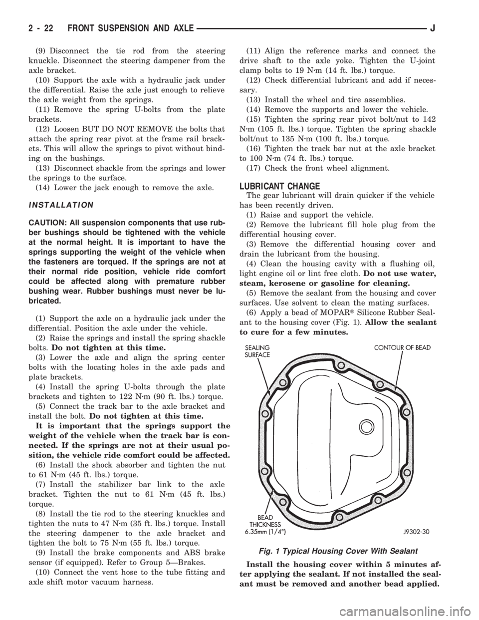
(6) Apply a bead of MOPARtSilicone Rubber Seal-
ant to the housing cover (Fig. 1).Allow the sealant
to cure for a few minutes.
Install the housing cover within 5 minutes af-
ter applying the sealant. If not installed the seal-
ant must be removed and another bead applied.
Fig. 1 Typical Housing Cover With Sealant
2 - 22 FRONT SUSPENSION AND AXLEJ
Page 68 of 1784
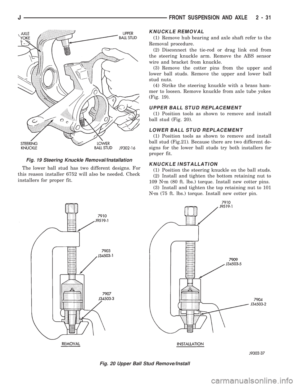
The lower ball stud has two different designs. For
this reason installer 6752 will also be needed. Check
installers for proper fit.
KNUCKLE REMOVAL
(1) Remove hub bearing and axle shaft refer to the
Removal procedure.
(2) Disconnect the tie-rod or drag link end from
the steering knuckle arm. Remove the ABS sensor
wire and bracket from knuckle.
(3) Remove the cotter pins from the upper and
lower ball studs. Remove the upper and lower ball
stud nuts.
(4) Strike the steering knuckle with a brass ham-
mer to loosen. Remove knuckle from axle tube yokes
(Fig. 19).
UPPER BALL STUD REPLACEMENT
(1) Position tools as shown to remove and install
ball stud (Fig. 20).
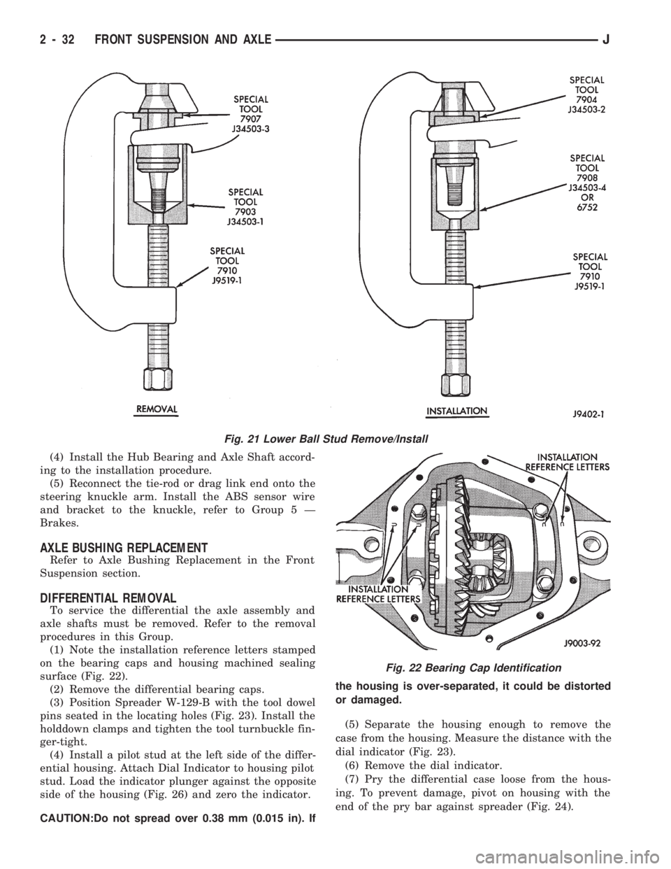
LOWER BALL STUD REPLACEMENT
(1) Position tools as shown to remove and install
ball stud (Fig.21). Because there are two different de-
signs for the lower ball studs try both installers for
proper fit.
KNUCKLE INSTALLATION
(1) Position the steering knuckle on the ball studs.
(2) Install and tighten the bottom retaining nut to
109 Nzm (80 ft. lbs.) torque. Install new cotter pins.
(3) Install and tighten the top retaining nut to 101
Nzm (75 ft. lbs.) torque. Install new cotter pin.
Fig. 19 Steering Knuckle Removal/Installation
Fig. 20 Upper Ball Stud Remove/Install
JFRONT SUSPENSION AND AXLE 2 - 31
Page 69 of 1784
(4) Install the Hub Bearing and Axle Shaft accord-
ing to the installation procedure.
(5) Reconnect the tie-rod or drag link end onto the
steering knuckle arm. Install the ABS sensor wire
and bracket to the knuckle, refer to Group 5 Ð
Brakes.
AXLE BUSHING REPLACEMENT
Refer to Axle Bushing Replacement in the Front
Suspension section.
DIFFERENTIAL REMOVAL
To service the differential the axle assembly and
axle shafts must be removed. Refer to the removal
procedures in this Group.
(1) Note the installation reference letters stamped
on the bearing caps and housing machined sealing
surface (Fig. 22).
(2) Remove the differential bearing caps.
(3) Position Spreader W-129-B with the tool dowel
pins seated in the locating holes (Fig. 23). Install the
holddown clamps and tighten the tool turnbuckle fin-
ger-tight.
(4) Install a pilot stud at the left side of the differ-
ential housing. Attach Dial Indicator to housing pilot
stud. Load the indicator plunger against the opposite
side of the housing (Fig. 26) and zero the indicator.
CAUTION:Do not spread over 0.38 mm (0.015 in). Ifthe housing is over-separated, it could be distorted
or damaged.
(5) Separate the housing enough to remove the
case from the housing. Measure the distance with the
dial indicator (Fig. 23).
(6) Remove the dial indicator.
(7) Pry the differential case loose from the hous-
ing. To prevent damage, pivot on housing with the
end of the pry bar against spreader (Fig. 24).
Fig. 21 Lower Ball Stud Remove/Install
Fig. 22 Bearing Cap Identification
2 - 32 FRONT SUSPENSION AND AXLEJ
Page 102 of 1784
MULTI-PORT FUEL INJECTION (MFI)ÐCOMPONENT DESCRIPTION/SYSTEM
OPERATION
INDEX
page page
Air Conditioning (A/C) Clutch RelayÐPCM Output.24
Air Conditioning (A/C) ControlsÐPCM Input.... 19
Auto Shut Down (ASD) RelayÐPCM Output.... 24
Automatic Shut Down (ASD) SenseÐPCM Input . 19
Battery VoltageÐPCM Input................ 19
Brake SwitchÐPCM Input.................. 20
Camshaft Position SensorÐPCM Input........ 20
Crankshaft Position SensorÐPCM Input....... 20
Data Link ConnectorÐPCM Input............ 20
Data Link ConnectorÐPCM Output........... 24
EMR LampÐPCM Output.................. 24
Engine Coolant Temperature SensorÐPCM Input . 21
Extended Idle SwitchÐPCM Input............ 21
Fuel InjectorsÐPCM Output................ 25
Fuel Pressure Regulator................... 30
Fuel Pump RelayÐPCM Output............. 25
Fuel Rail............................... 30
General Information....................... 17
Generator FieldÐPCM Output............... 25
Generator LampÐPCM Output.............. 25
Idle Air Control (IAC) MotorÐPCM Output...... 25
Ignition Circuit SenseÐPCM Input............ 21
Ignition CoilÐPCM Output.................. 26Intake Air Temperature SensorÐPCM Input.... 20
Malfunction Indicator LampÐPCM Output...... 26
Manifold Absolute Pressure (MAP) SensorÐ
PCM Input............................ 21
Open Loop/Closed Loop Modes of Operation . . . 27
Overdrive/Override Switch.................. 22
Oxygen (O2S) SensorÐPCM Input........... 22
Park/Neutral SwitchÐPCM Input............. 22
Power Ground........................... 22
Power Steering Pressure SwitchÐPCM Input . . . 22
Powertrain Control Module (PCM)............ 18
Radiator Fan RelayÐPCM Output............ 26
SCI ReceiveÐPCM Input.................. 22
SCI TransmitÐPCM Output................. 26
Sensor ReturnÐPCM Input................. 23
Shift IndicatorÐPCM Output................ 26
Speed ControlÐPCM Input................. 23
Speed ControlÐPCM Output................ 27
TachometerÐPCM Output.................. 27
Throttle Body............................ 29
Throttle Position Sensor (TPS)ÐPCM Input..... 23
Torque Converter Clutch RelayÐPCM Output . . . 27
Vehicle Speed SensorÐPCM Input........... 23
GENERAL INFORMATION
All 2.5L 4 cylinder and 4.0L 6 cylinder engines are
equipped with sequential Multi-Port Fuel Injection
(MFI). The MFI system provides precise air/fuel ra-
tios for all driving conditions.
The Powertrain Control Module (PCM) operates
the fuel system. The PCM was formerly referred to
as the SBEC or engine controller. The PCM is a pre-
programmed, dual microprocessor digital computer.
It regulates ignition timing, air-fuel ratio, emission
control devices, charging system, speed control, air
conditioning compressor clutch engagement and idle
speed. The PCM can adapt its programming to meet
changing operating conditions.
Powertrain Control Module (PCM) Inputsrep-
resent the instantaneous engine operating conditions.
Air-fuel mixture and ignition timing calibrations for
various driving and atmospheric conditions are pre-
programmed into the PCM. The PCM monitors and
analyzes various inputs. It then computes engine fuel
and ignition timing requirements based on these in-
puts. Fuel delivery control and ignition timing will
then be adjusted accordingly.
Other inputs to the PCM are provided by the brake
light switch, air conditioning select switch and the
speed control switches. All inputs to the PCM are
converted into signals.
Electrically operated fuel injectors spray fuel in
precise metered amounts into the intake port directlyabove the intake valve. The injectors are fired in a
specific sequence by the PCM. The PCM maintains
an air/fuel ratio of 14.7 to 1 by constantly adjusting
injector pulse width. Injector pulse width is the
length of time that the injector opens and sprays fuel
into the chamber. The PCM adjusts injector pulse
width by opening and closing the ground path to the
injector.
Manifold absolute pressure (air density) and engine
rpm (speed) are the primary inputs that determine
fuel injector pulse width. The PCM also monitors
other inputs when adjusting air-fuel ratio.
Inputs That Effect Fuel Injector Pulse Width
²Exhaust gas oxygen content
²Engine coolant temperature
²Manifold absolute pressure (MAP)
²Engine speed
²Throttle position
²Battery voltage
²Air conditioning selection
²Transmission gear selection (automatic transmis-
sions only)
²Speed control
The powertrain control module (PCM) adjusts igni-
tion timing by controlling ignition coil operation. The
ignition coil receives battery voltage when the igni-
tion key is in the run or starter position. The PCM
provides a ground for the ignition coil. The coil dis-
JFUEL SYSTEM 14 - 17
Page 103 of 1784
charges when the PCM supplies a ground. By switch-
ing the ground path on and off, the PCM regulates
ignition timing.
The sensors and switches that provide inputs to the
powertrain control module (PCM) comprise the En-
gine Control System. It is also comprised of the PCM
Outputs (engine control devices that the are operated
by the PCM).
SYSTEM DIAGNOSIS
The powertrain control module (PCM) tests many
of its own input and output circuits. If a Diagnostic
Trouble Code (DTC) is found in a major system, this
information is stored in the PCM memory. Refer to
On-Board Diagnostics in the MFI SystemÐGeneral
Diagnosis section of this group for DTC information.
POWERTRAIN CONTROL MODULE (PCM)
The PCM operates the fuel system. The PCM was
formerly referred to as the SBEC or engine control-
ler. The PCM is a pre-programmed, dual micropro-
cessor digital computer. It regulates ignition timing,
air-fuel ratio, emission control devices, charging sys-
tem, speed control, air conditioning compressor
clutch engagement and idle speed. The PCM can
adapt its programming to meet changing operating
conditions.
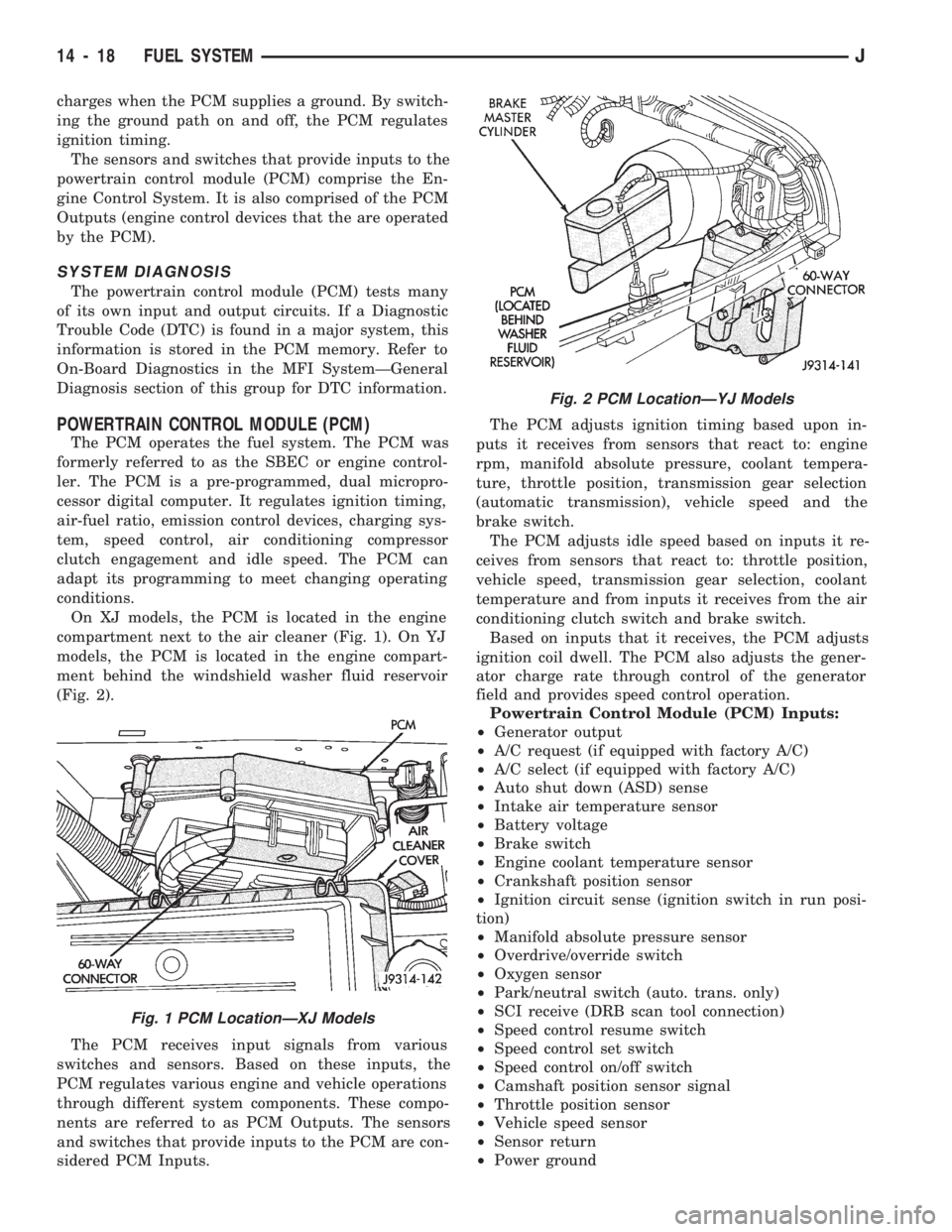
On XJ models, the PCM is located in the engine
compartment next to the air cleaner (Fig. 1). On YJ
models, the PCM is located in the engine compart-
ment behind the windshield washer fluid reservoir
(Fig. 2).
The PCM receives input signals from various
switches and sensors. Based on these inputs, the
PCM regulates various engine and vehicle operations
through different system components. These compo-
nents are referred to as PCM Outputs. The sensors
and switches that provide inputs to the PCM are con-
sidered PCM Inputs.The PCM adjusts ignition timing based upon in-
puts it receives from sensors that react to: engine
rpm, manifold absolute pressure, coolant tempera-
ture, throttle position, transmission gear selection
(automatic transmission), vehicle speed and the
brake switch.
The PCM adjusts idle speed based on inputs it re-
ceives from sensors that react to: throttle position,
vehicle speed, transmission gear selection, coolant
temperature and from inputs it receives from the air
conditioning clutch switch and brake switch.
Based on inputs that it receives, the PCM adjusts
ignition coil dwell. The PCM also adjusts the gener-
ator charge rate through control of the generator
field and provides speed control operation.
Powertrain Control Module (PCM) Inputs:
²Generator output
²A/C request (if equipped with factory A/C)
²A/C select (if equipped with factory A/C)
²Auto shut down (ASD) sense
²Intake air temperature sensor
²Battery voltage
²Brake switch
²Engine coolant temperature sensor
²Crankshaft position sensor
²Ignition circuit sense (ignition switch in run posi-
tion)
²Manifold absolute pressure sensor
²Overdrive/override switch
²Oxygen sensor
²Park/neutral switch (auto. trans. only)
²SCI receive (DRB scan tool connection)
²Speed control resume switch
²Speed control set switch
²Speed control on/off switch
²Camshaft position sensor signal
²Throttle position sensor
²Vehicle speed sensor
²Sensor return
²Power ground
Fig. 1 PCM LocationÐXJ Models
Fig. 2 PCM LocationÐYJ Models
14 - 18 FUEL SYSTEMJ
Page 104 of 1784

²Signal ground
Powertrain Control Module (PCM) Outputs
²A/C clutch relay
²Idle air control (IAC) motor
²Auto shut down (ASD) relay
²Generator field
²Malfunction indicator lamp
²Fuel injectors
²Fuel pump relay
²Ignition coil
²SCI transmit (DRB scan tool connection)
²Shift indicator lamp (manual transmission only)
²Speed control vacuum solenoid
²Speed control vent solenoid
²Tachometer (on instrument panel, if equipped)
²Torque converter clutch relay (3-speed auto. trans.
only)
The PCM contains a voltage convertor. This con-
verts battery voltage to a regulated 8.0 volts. It is
used to power the crankshaft position sensor and
camshaft position sensor. The PCM also provides a
five (5) volt supply for the Manifold Absolute Pres-
sure (MAP) sensor and Throttle Position Sensor
(TPS).
AIR CONDITIONING (A/C) CONTROLSÐPCM INPUT
The A/C control system information applies to fac-
tory installed air conditioning units only.
A/C SELECT SIGNAL:When the A/C switch is
in the ON position and the A/C low pressure switch
is closed, an input signal is sent to the powertrain
control module (PCM). The signal informs the PCM
that the A/C has been selected. The PCM adjusts idle
speed to a pre-programmed rpm through the idle air
control (IAC) motor to compensate for increased en-
gine load.
A/C REQUEST SIGNAL:Once A/C has been se-
lected, the PCM receives the A/C request signal from
the evaporator switch. The input indicates that the
evaporator temperature is in the proper range for
A/C application. The PCM uses this input to cycle
the A/C compressor clutch (through the A/C relay). It
will also determine the correct engine idle speed
through the IAC motor position.
If the A/C low pressure switch opens (indicating a
low refrigerant level), the PCM will not receive an
A/C select signal. The PCM will then remove the
ground from the A/C relay. This will deactivate the
A/C compressor clutch.
If the evaporator switch opens, (indicating that
evaporator is not in proper temperature range), the
PCM will not receive the A/C request signal. The
PCM will then remove the ground from the A/C re-
lay, deactivating the A/C compressor clutch.
AUTOMATIC SHUT DOWN (ASD) SENSEÐPCM
INPUT
A 12 volt signal at this input indicates to the PCM
that the ASD has been activated. The ASD relay is
located in the power distribution center (PDC) in the
engine compartment (Figs. 3 or 4). It is used to con-
nect oxygen sensor heater element, ignition coil, gen-
erator field winding and fuel injectors to 12 volt +
power supply. Also refer to Automatic Shut Down
RelayÐPCM Output.
This input is used only to sense that the ASD relay
is energized. If the PCM does not see 12 volts at this
input when the ASD should be activated, it will set a
Diagnostic Trouble Code (DTC).
BATTERY VOLTAGEÐPCM INPUT
The battery voltage input provides power to the
powertrain control module (PCM). It also informs the
PCM what voltage level is supplied to the ignition
coil and fuel injectors.
If battery voltage is low, the PCM will increase in-
jector pulse width (period of time that the injector is
Fig. 3 Power Distribution CenterÐYJ Models
Fig. 4 Power Distribution CenterÐXJ Models
JFUEL SYSTEM 14 - 19