1994 JEEP CHEROKEE park assist
[x] Cancel search: park assistPage 133 of 1784

87 and 30. Continuity should not be present between
terminals number 87A and 30.
(8) Disconnect jumper wires from relay and 12
Volt power source.
If continuity or resistance tests did not pass, re-
place relay. If tests passed, refer to Group 8W, Wir-
ing Diagrams for additional circuit information. Also
refer to the appropriate Powertrain Diagnostic Proce-
dures manual for operation of the DRB scan tool.
STARTER MOTOR RELAY TEST
Refer to Group 8A, Battery/Starting/Charging/Sys-
tem Diagnostics, for starter motor relay testing.
INJECTOR TEST
Disconnect the injector wire connector from the in-
jector. Place an ohmmeter on the injector terminals.
Resistance reading should be approximately 14.5
ohms61.2 ohms at 20ÉC (68ÉF). Proceed to following
Injector Diagnosis chart.
FUEL SYSTEM PRESSURE TEST
Refer to the Fuel Delivery System section of this
group. See Fuel System Pressure Test.
ON-BOARD DIAGNOSTICS (OBD)
The Powertrain Control Module (PCM) has been
programmed to monitor many different circuits of the
fuel injection system. If a problem is sensed in a
monitored circuit often enough to indicate an actual
problem, a Diagnostic Trouble Code (DTC) is stored.
The DTC will be stored in the PCM memory for
eventual display to the service technician. If the
problem is repaired or ceases to exist, the PCM can-
cels the DTC after 51 engine starts.
Certain criteria must be met for a diagnostic trou-
ble code (DTC) to be entered into PCM memory. The
criteria may be a specific range of engine rpm, en-
gine temperature and/or input voltage to the PCM.
It is possible that a DTC for a monitored circuit
may not be entered into memory even though a mal-
function has occurred. This may happen because one
of the DTC criteria for the circuit has not been met.
Example: assume that one of the criteria for the
MAP sensor circuit is that the engine must be oper-
ating between 750 and 2000 rpm to be monitored for
a DTC. If the MAP sensor output circuit shorts to
ground when the engine rpm is above 2400 rpm, a 0
volt input will be seen by the PCM. A DTC will not
be entered into memory because the condition does
not occur within the specified rpm range.
A DTC indicates that the powertrain control mod-
ule (PCM) has recognized an abnormal signal in a
circuit or the system. A DTC may indicate the result
of a failure, but never identify the failed component
directly.There are several operating conditions that the
PCM does not monitor and set a DTC for. Refer to
the following Monitored Circuits and Non-Monitored
Circuits in this section.
MONITORED CIRCUITS
The powertrain control module (PCM) can detect
certain problems in the fuel injection system.
Open or Shorted Circuit- The PCM can deter-
mine if sensor output (which is the input to PCM) is
within proper range. It also determines if the circuit
is open or shorted.
Output Device Current Flow- The PCM senses
whether the output devices are hooked up.
If there is a problem with the circuit, the PCM
senses whether the circuit is open, shorted to ground
(-), or shorted to (+) voltage.
Oxygen Sensor- The PCM can determine if the
oxygen sensor is switching between rich and lean.
This is, once the system has entered Closed Loop. Re-
fer to Open Loop/Closed Loop Modes Of Operation in
the Component Description/System Operation section
for an explanation of Closed (or Open) Loop opera-
tion.
NON-MONITORED CIRCUITS
The PCM does not monitor the following circuits,
systems or conditions that could have malfunctions
that result in driveability problems. A Diagnostic
Trouble Code (DTC) may not be displayed for these
conditions.
Fuel Pressure: Fuel pressure is controlled by the
vacuum assisted fuel pressure regulator. The PCM
cannot detect a clogged fuel pump inlet filter, clogged
in-line fuel filter, or a pinched fuel supply or return
line. However, these could result in a rich or lean
condition causing an oxygen sensor DTC to be stored
in the PCM.
Secondary Ignition Circuit: The PCM cannot
detect an inoperative ignition coil, fouled or worn
spark plugs, ignition cross firing, or open circuited
spark plug cables.
Engine Timing: The PCM cannot detect an incor-
rectly indexed timing chain, camshaft sprocket or
crankshaft sprocket. The PCM also cannot detect an
incorrectly indexed distributor. However, these could
result in a rich or lean condition causing an oxygen
sensor DTC to be stored in the PCM.
Cylinder Compression: The PCM cannot detect
uneven, low, or high engine cylinder compression.
Exhaust System: The PCM cannot detect a
plugged, restricted or leaking exhaust system.
Fuel Injector Malfunctions: The PCM cannot de-
termine if the fuel injector is clogged, or the wrong
injector is installed. However, these could result in a
rich or lean condition causing an oxygen sensor DTC
to be stored in the PCM.
14 - 48 FUEL SYSTEMJ
Page 158 of 1784
assembled, they will not function. In addition, since
the adjuster mechanism only works during reverse
stops, it is important that complete stops be made.
The adjuster mechanism does not operate when roll-
ing stops are made in reverse. The vehicle must be
brought to a complete halt before the adjuster lever
will turn the adjuster screw.
A condition where the parking brakes do not hold,
will most probably be due to a wheel brake compo-
nent.
Items to look for when diagnosing a parking brake
problem, are:
²rear brakeshoe wear
²rear brakedrum wear
²brakedrums machined beyond allowable diameter
(oversize)
²parking brake front cable not secured to lever
²parking brake rear cable seized
²parking brake strut reversed
²parking brake strut not seated in both shoes
²parking brake lever not seated in secondary shoe
²parking brake lever or brakeshoe bind on support
plate
²brakeshoes reversed
²adjuster screws seized
²adjuster screws reversed
²holddown or return springs misassembled or lack
tension
²wheel cylinder pistons seized
Brake drums that are machined oversize are diffi-
cult to identify. If oversize drums are suspected, the
diameter of the braking surface will have to be
checked with an accurate drum gauge. Oversize
drums will cause low brake pedal and lack of park-
ing brake holding ability.
Improper parking brake strut and lever installa-
tion will result in unsatisfactory parking brake oper-
ation. Intermixing the adjuster screws will cause
drag, bind and pull along with poor parking brake
operation.
Parking brake adjustment and parts replacement
procedures are described in the Parking Brake sec-
tion.
MASTER CYLINDER/POWER BOOSTER TEST
(1) Start engine and check booster vacuum hose
connections. Hissing noise indicates vacuum leak.
Correct any vacuum leak before proceeding.
(2) Stop engine and shift transmission into Neu-
tral.
(3) Pump brake pedal until all vacuum reserve in
booster is depleted.
(4) Press and hold brake pedal under light foot
pressure.
(a) If pedal holds firm, proceed to step (5).
(b) If pedal does not hold firm and falls away,
master cylinder is faulty (internal leakage). Over-
haul or replace cylinder.(5) Start engine and note pedal action.
(a) If pedal falls away slightly under light foot
pressure then holds firm, proceed to step (6).
(b) If no pedal action is discernible, power
booster or vacuum check valve is faulty. Install
known good check valve and repeat steps (2)
through (5).
(6) Rebuild booster vacuum reserve as follows: Re-
lease brake pedal. Increase engine speed to 1500
rpm, close throttle and immediately turn off ignition.
(7) Wait a minimum of 90 seconds and try brake
action again. Booster should provide two or more
vacuum assisted pedal applications. If vacuum assist
is not provided, perform booster and check valve vac-
uum tests.
POWER BOOSTER CHECK VALVE TEST
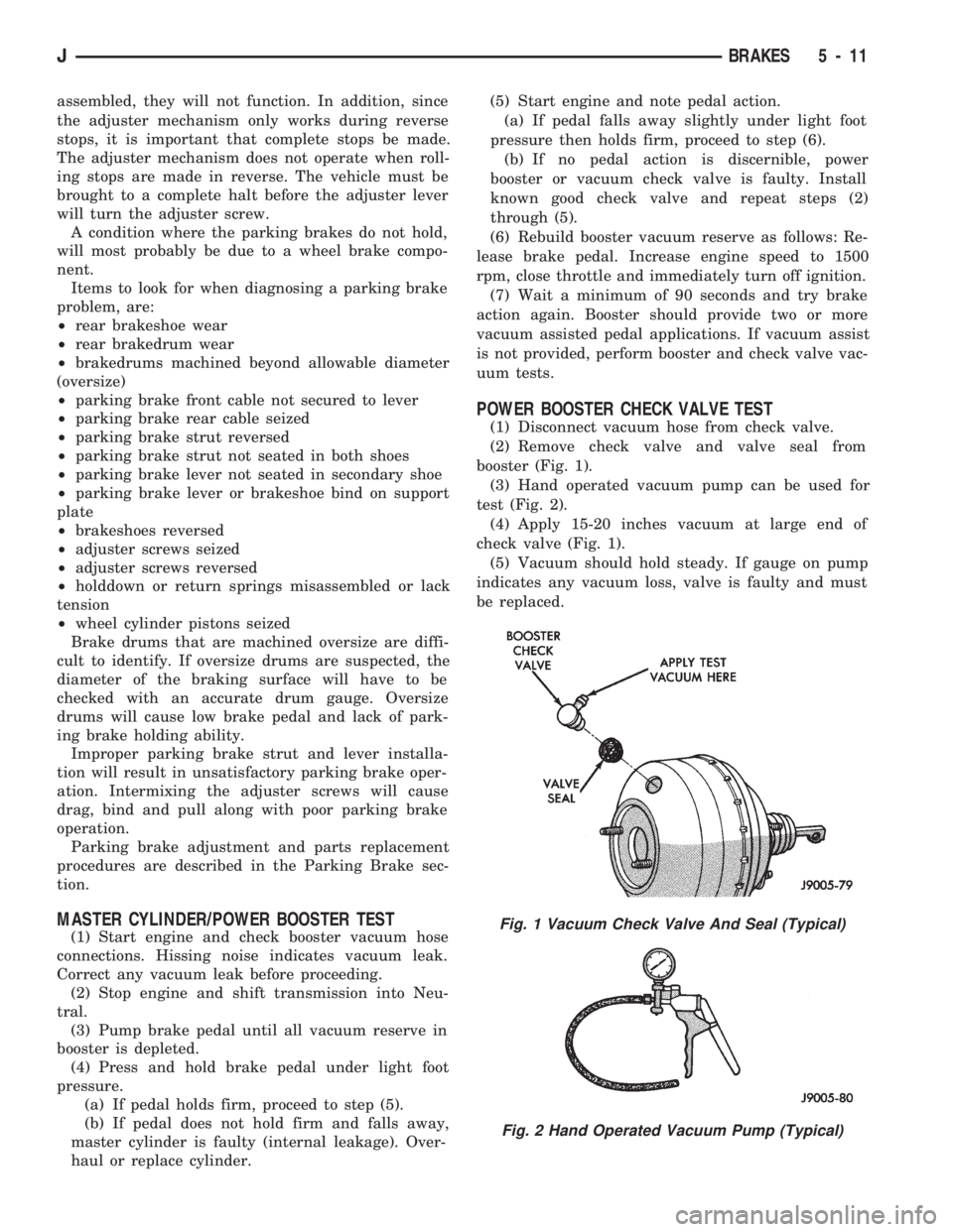
(1) Disconnect vacuum hose from check valve.
(2) Remove check valve and valve seal from
booster (Fig. 1).
(3) Hand operated vacuum pump can be used for
test (Fig. 2).
(4) Apply 15-20 inches vacuum at large end of
check valve (Fig. 1).
(5) Vacuum should hold steady. If gauge on pump
indicates any vacuum loss, valve is faulty and must
be replaced.
Fig. 1 Vacuum Check Valve And Seal (Typical)
Fig. 2 Hand Operated Vacuum Pump (Typical)
JBRAKES 5 - 11
Page 278 of 1784
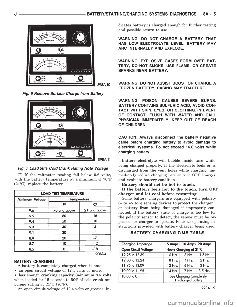
(7) If the voltmeter reading fell below 9.6 volts,
with the battery temperature at a minimum of 70ÉF
(21ÉC), replace the battery.
BATTERY CHARGING
A battery is completely charged when it has:
²an open circuit voltage of 12.4 volts or more.
²has enough cranking capacity (minimum 9.6 volts
when loaded for 15 seconds to 50% of cold crank am-
perage rating at 21ÉC (70ÉF).
An open circuit voltage of 12.4 volts or greater, in-dicates battery is charged enough for further testing
and possible return to use.
WARNING: DO NOT CHARGE A BATTERY THAT
HAS LOW ELECTROLYTE LEVEL. BATTERY MAY
ARC INTERNALLY AND EXPLODE.
WARNING: EXPLOSIVE GASES FORM OVER BAT-
TERY, DO NOT SMOKE, USE FLAME, OR CREATE
SPARKS NEAR BATTERY.
WARNING: DO NOT ASSIST BOOST OR CHARGE A
FROZEN BATTERY, CASING MAY FRACTURE.
WARNING: POISON, CAUSES SEVERE BURNS.
BATTERY CONTAINS SULFURIC ACID, AVOID CON-
TACT WITH SKIN, EYES, OR CLOTHING. IN EVENT
OF CONTACT, FLUSH WITH WATER AND CALL
PHYSICIAN IMMEDIATELY. KEEP OUT OF REACH
OF CHILDREN.
CAUTION: Always disconnect the battery negative
cable before charging battery to avoid damage to
electrical systems. Do not exceed 16.0 volts while
charging battery.
Battery electrolyte will bubble inside case while
being charged properly. If the electrolyte boils or is
discharged from the vent holes while charging, im-
mediately reduce charging rate or turn OFF charger
and evaluate battery condition.
Battery should not be hot to touch.
If the battery feels hot to the touch, turn OFF
charger and let cool before restarting.
Some battery chargers are equipped with polarity
(+ to +/- to -) sensing devices to protect the charger
or battery from being damaged if improperly con-
nected. If the battery state of charge is too low for
the polarity sensor to detect, the sensor must be by-
passed for charger to operate. Refer to operating in-
structions provided with battery charger being used.
Fig. 6 Remove Surface Charge from Battery
Fig. 7 Load 50% Cold Crank Rating Note Voltage
BATTERY CHARGING TIME TABLE
JBATTERY/STARTING/CHARGING SYSTEMS DIAGNOSTICS 8A - 5
Page 1009 of 1784
87 and 30. Continuity should not be present between
terminals number 87A and 30.
(8) Disconnect jumper wires from relay and 12
Volt power source.
If continuity or resistance tests did not pass, re-
place relay. If tests passed, refer to Group 8W, Wir-
ing Diagrams for additional circuit information. Also
refer to the appropriate Powertrain Diagnostic Proce-
dures manual for operation of the DRB scan tool.
STARTER MOTOR RELAY TEST
Refer to Group 8A, Battery/Starting/Charging/Sys-
tem Diagnostics, for starter motor relay testing.
INJECTOR TEST
Disconnect the injector wire connector from the in-
jector. Place an ohmmeter on the injector terminals.
Resistance reading should be approximately 14.5
ohms61.2 ohms at 20ÉC (68ÉF). Proceed to following
Injector Diagnosis chart.
FUEL SYSTEM PRESSURE TEST
Refer to the Fuel Delivery System section of this
group. See Fuel System Pressure Test.
ON-BOARD DIAGNOSTICS (OBD)
The Powertrain Control Module (PCM) has been
programmed to monitor many different circuits of the
fuel injection system. If a problem is sensed in a
monitored circuit often enough to indicate an actual
problem, a Diagnostic Trouble Code (DTC) is stored.
The DTC will be stored in the PCM memory for
eventual display to the service technician. If the
problem is repaired or ceases to exist, the PCM can-
cels the DTC after 51 engine starts.
Certain criteria must be met for a diagnostic trou-
ble code (DTC) to be entered into PCM memory. The
criteria may be a specific range of engine rpm, en-
gine temperature and/or input voltage to the PCM.
It is possible that a DTC for a monitored circuit
may not be entered into memory even though a mal-
function has occurred. This may happen because one
of the DTC criteria for the circuit has not been met.
Example: assume that one of the criteria for the
MAP sensor circuit is that the engine must be oper-
ating between 750 and 2000 rpm to be monitored for
a DTC. If the MAP sensor output circuit shorts to
ground when the engine rpm is above 2400 rpm, a 0
volt input will be seen by the PCM. A DTC will not
be entered into memory because the condition does
not occur within the specified rpm range.
A DTC indicates that the powertrain control mod-
ule (PCM) has recognized an abnormal signal in a
circuit or the system. A DTC may indicate the result
of a failure, but never identify the failed component
directly.There are several operating conditions that the
PCM does not monitor and set a DTC for. Refer to
the following Monitored Circuits and Non-Monitored
Circuits in this section.
MONITORED CIRCUITS
The powertrain control module (PCM) can detect
certain problems in the fuel injection system.
Open or Shorted Circuit- The PCM can deter-
mine if sensor output (which is the input to PCM) is
within proper range. It also determines if the circuit
is open or shorted.
Output Device Current Flow- The PCM senses
whether the output devices are hooked up.
If there is a problem with the circuit, the PCM
senses whether the circuit is open, shorted to ground
(-), or shorted to (+) voltage.
Oxygen Sensor- The PCM can determine if the
oxygen sensor is switching between rich and lean.
This is, once the system has entered Closed Loop. Re-
fer to Open Loop/Closed Loop Modes Of Operation in
the Component Description/System Operation section
for an explanation of Closed (or Open) Loop opera-
tion.
NON-MONITORED CIRCUITS
The PCM does not monitor the following circuits,
systems or conditions that could have malfunctions
that result in driveability problems. A Diagnostic
Trouble Code (DTC) may not be displayed for these
conditions.
Fuel Pressure: Fuel pressure is controlled by the
vacuum assisted fuel pressure regulator. The PCM
cannot detect a clogged fuel pump inlet filter, clogged
in-line fuel filter, or a pinched fuel supply or return
line. However, these could result in a rich or lean
condition causing an oxygen sensor DTC to be stored
in the PCM.
Secondary Ignition Circuit: The PCM cannot
detect an inoperative ignition coil, fouled or worn
spark plugs, ignition cross firing, or open circuited
spark plug cables.
Engine Timing: The PCM cannot detect an incor-
rectly indexed timing chain, camshaft sprocket or
crankshaft sprocket. The PCM also cannot detect an
incorrectly indexed distributor. However, these could
result in a rich or lean condition causing an oxygen
sensor DTC to be stored in the PCM.
Cylinder Compression: The PCM cannot detect
uneven, low, or high engine cylinder compression.
Exhaust System: The PCM cannot detect a
plugged, restricted or leaking exhaust system.
Fuel Injector Malfunctions: The PCM cannot de-
termine if the fuel injector is clogged, or the wrong
injector is installed. However, these could result in a
rich or lean condition causing an oxygen sensor DTC
to be stored in the PCM.
14 - 48 FUEL SYSTEMJ
Page 1038 of 1784
STEERING
CONTENTS
page page
GENERAL INFORMATION.................. 1
MANUAL STEERING GEAR............... 35
NON-TILT STEERING COLUMN............ 50
POWER STEERING PUMP................. 9
POWER STEERING SYSTEM DIAGNOSIS..... 3
RECIRCULATING BALL POWER STEERING GEAR.19STEERING COLUMN GENERAL SERVICE.... 45
STEERING LINKAGEÐXJ................. 14
STEERING LINKAGEÐYJ................. 17
STEERING RHD........................ 69
TILT STEERING COLUMN................ 59
TORQUE SPECIFICATIONS................ 73
GENERAL INFORMATION
STEERING SYSTEM COMPONENTS
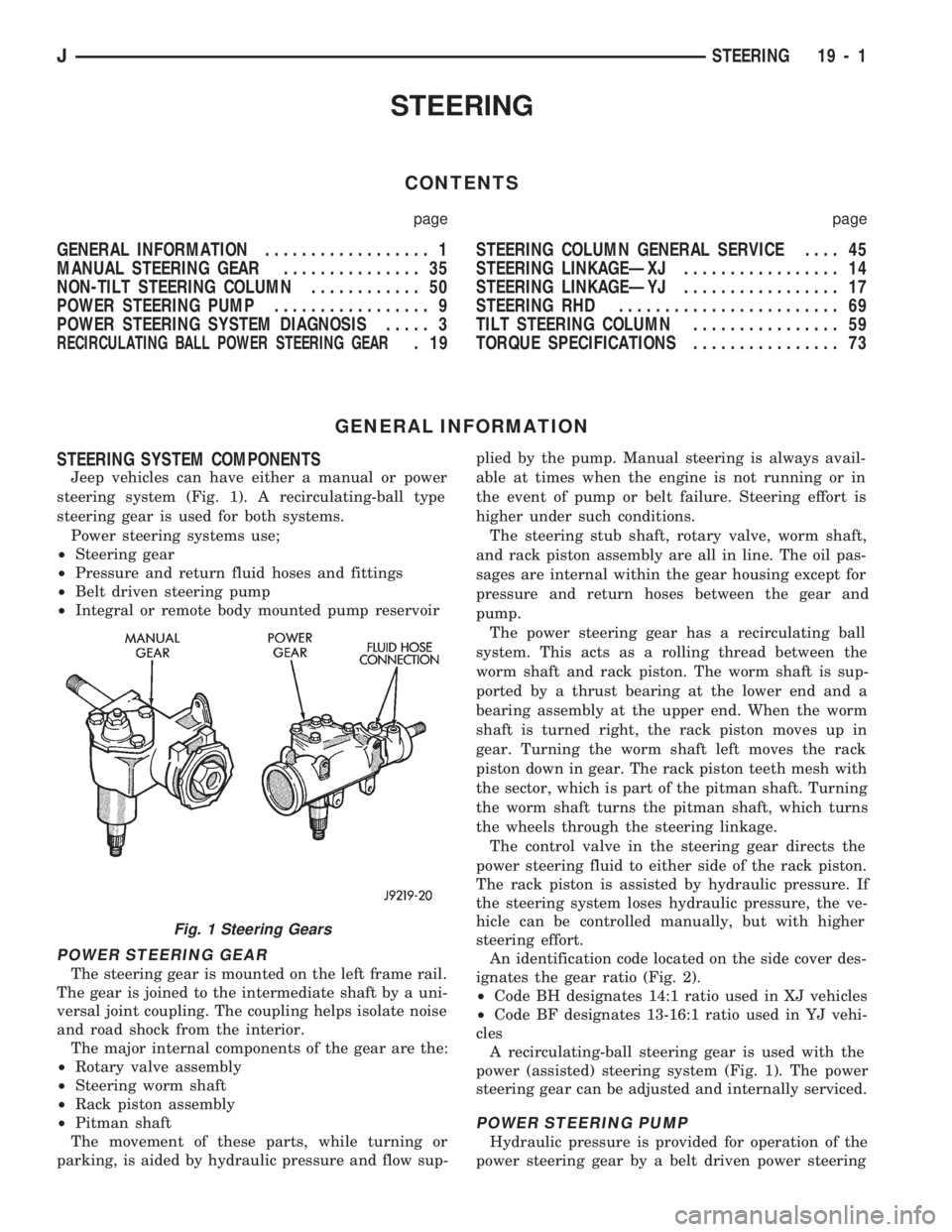
Jeep vehicles can have either a manual or power
steering system (Fig. 1). A recirculating-ball type
steering gear is used for both systems.
Power steering systems use;
²Steering gear
²Pressure and return fluid hoses and fittings
²Belt driven steering pump
²Integral or remote body mounted pump reservoir
POWER STEERING GEAR
The steering gear is mounted on the left frame rail.
The gear is joined to the intermediate shaft by a uni-
versal joint coupling. The coupling helps isolate noise
and road shock from the interior.
The major internal components of the gear are the:
²Rotary valve assembly
²Steering worm shaft
²Rack piston assembly
²Pitman shaft
The movement of these parts, while turning or
parking, is aided by hydraulic pressure and flow sup-plied by the pump. Manual steering is always avail-
able at times when the engine is not running or in
the event of pump or belt failure. Steering effort is
higher under such conditions.
The steering stub shaft, rotary valve, worm shaft,
and rack piston assembly are all in line. The oil pas-
sages are internal within the gear housing except for
pressure and return hoses between the gear and
pump.
The power steering gear has a recirculating ball
system. This acts as a rolling thread between the
worm shaft and rack piston. The worm shaft is sup-
ported by a thrust bearing at the lower end and a
bearing assembly at the upper end. When the worm
shaft is turned right, the rack piston moves up in
gear. Turning the worm shaft left moves the rack
piston down in gear. The rack piston teeth mesh with
the sector, which is part of the pitman shaft. Turning
the worm shaft turns the pitman shaft, which turns
the wheels through the steering linkage.
The control valve in the steering gear directs the
power steering fluid to either side of the rack piston.
The rack piston is assisted by hydraulic pressure. If
the steering system loses hydraulic pressure, the ve-
hicle can be controlled manually, but with higher
steering effort.
An identification code located on the side cover des-
ignates the gear ratio (Fig. 2).
²Code BH designates 14:1 ratio used in XJ vehicles
²Code BF designates 13-16:1 ratio used in YJ vehi-
cles
A recirculating-ball steering gear is used with the
power (assisted) steering system (Fig. 1). The power
steering gear can be adjusted and internally serviced.
POWER STEERING PUMP
Hydraulic pressure is provided for operation of the
power steering gear by a belt driven power steering
Fig. 1 Steering Gears
JSTEERING 19 - 1
Page 1648 of 1784
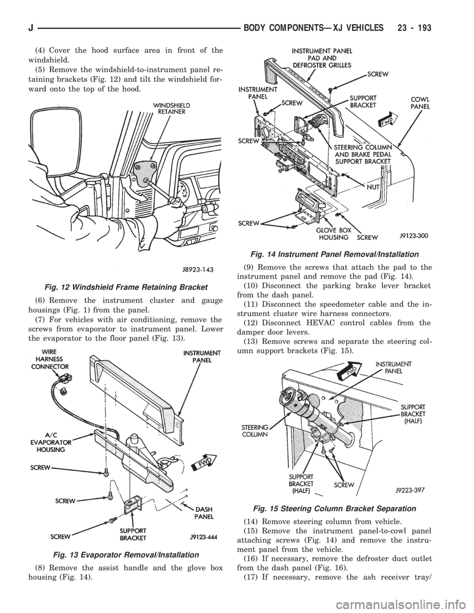
(4) Cover the hood surface area in front of the
windshield.
(5) Remove the windshield-to-instrument panel re-
taining brackets (Fig. 12) and tilt the windshield for-
ward onto the top of the hood.
(6) Remove the instrument cluster and gauge
housings (Fig. 1) from the panel.
(7) For vehicles with air conditioning, remove the
screws from evaporator to instrument panel. Lower
the evaporator to the floor panel (Fig. 13).
(8) Remove the assist handle and the glove box
housing (Fig. 14).(9) Remove the screws that attach the pad to the
instrument panel and remove the pad (Fig. 14).
(10) Disconnect the parking brake lever bracket
from the dash panel.
(11) Disconnect the speedometer cable and the in-
strument cluster wire harness connectors.
(12) Disconnect HEVAC control cables from the
damper door levers.
(13) Remove screws and separate the steering col-
umn support brackets (Fig. 15).
(14) Remove steering column from vehicle.
(15) Remove the instrument panel-to-cowl panel
attaching screws (Fig. 14) and remove the instru-
ment panel from the vehicle.
(16) If necessary, remove the defroster duct outlet
from the dash panel (Fig. 16).
(17) If necessary, remove the ash receiver tray/
Fig. 12 Windshield Frame Retaining Bracket
Fig. 13 Evaporator Removal/Installation
Fig. 14 Instrument Panel Removal/Installation
Fig. 15 Steering Column Bracket Separation
JBODY COMPONENTSÐXJ VEHICLES 23 - 193
Page 1746 of 1784
ASSEMBLY REPLACEMENTÐYJ VEHICLES,
DRIVE AXLE; FRONT SUSPENSION AND
AXLE...............................2-21
ASSEMBLY REPLACEMENTÐYJ VEHICLES,
DRIVE AXLE; REAR SUSPENSION AND
AXLES..............................3-12
ASSEMBLY (SHORT BLOCK), SERVICE
ENGINE..............................9-4
ASSEMBLY TIPS, TRANSMISSION........21-146
ASSEMBLY, TRANSFER CASE......21-282,21-306
ASSEMBLYÐXJ VEHICLES, ENGINE....9-14,9-54
ASSEMBLYÐYJ VEHICLES, ENGINE....9-16,9-57
ASSEMBLY/INSTALLATION, PINION
GEAR; FRONT SUSPENSION AND AXLE....2-40
ASSEMBLY/INSTALLATION, PINION
GEAR; REAR SUSPENSION AND AXLES....3-22
ASSIST HANDLE, FULL-METAL DOOR.....23-175
ASSIST HANDLEÐXJ VEHICLES.........23-118
AUTO SHUT DOWN (ASD) RELAYÐPCM
OUTPUT............................14-24
AUTOMATIC BELT TENSIONERÐXJ
MODELS............................7-36
AUTOMATIC, PARK-LOCK CABLEÐ
CONSOLE SHIFT.....................19-45
AUTOMATIC SHUT DOWN (ASD) RELAY;
FUEL SYSTEM.......................14-54
AUTOMATIC SHUT DOWN (ASD) RELAY;
IGNITION SYSTEMS..........8D-1,8D-8,8D-20
AUTOMATIC SHUT DOWN (ASD) RELAY
TESTING...........................14-43
AUTOMATIC SHUT DOWN (ASD)
SENSEÐPCM INPUT..................14-19
AUTOMATIC TRANSMISSION..............0-23
AUTOMATIC TRANSMISSION, 30RH/
32RH..............................21-66
AUTOMATIC TRANSMISSION, AW-4.......21-156
AW-4 AUTOMATIC TRANSMISSION.......21-156
AW-4 BUSHING AND PISTON CLEARANCE . . 21-326
AW-4 CLUTCH AND BRAKE PACK
REQUIREMENTS....................21-328
AW-4 CLUTCH DISC AND PLATE
THICKNESS........................21-325
AW-4 GENERAL SPECIFICATIONS........21-324
AW-4 IN-VEHICLE SERVICE.............21-173
AW-4 OIL PUMP WEAR LIMITS..........21-325
AW-4 RETAINER AND PISTON
SPECIFICATIONS....................21-327
AW-4 TORQUE SPECIFICATIONS.........21-331
AW-4 TRANSMISSION DIAGNOSIS.......21-167
AW-4 TRANSMISSION OVERHAUL........21-192
AW-4 TRANSMISSION REMOVAL AND
INSTALLATION......................21-189
AW-4 VALVE AND SPRING
IDENTIFICATION....................21-330
AW-4 VALVE BODY CHECK BALL
DIMENSIONS.......................21-328
AX 15 MANUAL TRANSMISSION..........21-32
AX 15 MANUAL TRANSMISSION,
TORQUE SPECIFICATIONS.............21-320
AX 4/5 MANUAL TRANSMISSION..........21-1
AXLE (2WD), MODEL 30 AXLE AND TUBE . . . 2-20
AXLE 8 1/4 INCH, REAR.........3-29,3-44,3-50
AXLE ALIGNMENT, REAR..................3-8
AXLE AND TUBE AXLE (2WD), MODEL 30 . . . 2-20
AXLE ASSEMBLY REPLACEMENTÐXJ
VEHICLES, DRIVE; FRONT SUSPENSION
AND AXLE...........................2-21
AXLE ASSEMBLY REPLACEMENTÐ
XJ VEHICLES, DRIVE; REAR SUSPENSION
AND AXLES......................3-11,3-30
AXLE ASSEMBLY REPLACEMENTÐ
YJ VEHICLES, DRIVE; FRONT SUSPENSION
AND AXLE...........................2-21
AXLE ASSEMBLY REPLACEMENTÐ
YJ VEHICLES, DRIVE; REAR SUSPENSION
AND AXLES..........................3-12
AXLE BUSHING REPLACEMENT........2-11,2-32
AXLE, FRONT DRIVE.....................2-3
AXLE, MODEL 30 FRONT.............2-46,2-47
AXLE MODEL 35, REAR........3-11, 3-28, 3-50
AXLE NOISE/VIBRATION DIAGNOSIS;
FRONT SUSPENSION AND AXLE
..........2-16
AXLE NOISE/VIBRATION DIAGNOSIS;
REAR SUSPENSION AND AXLES
..........3-7
AXLE SHAFT
...........................3-14
AXLE SHAFTÐCARDAN U-JOINT
...........2-25AXLE SHAFT, HUB BEARING..............2-24
AXLE SHAFT OIL SEAL REPLACEMENT,
INNER..............................2-33
AXLE SHAFT SEAL AND BEARING..........3-15
AXLE SHAFT, SEAL AND BEARING
SERVICE............................3-31
AXLE SPECIFICATIONS; FRONT
SUSPENSION AND AXLE................2-46
AXLE SPECIFICATIONS; REAR
SUSPENSION AND AXLES...........3-28,3-44
AXLEÐYJ VEHICLES, VACUUM
DISCONNECT.........................2-26
AXLES................................3-1
AXLES, FRONT AND REAR................0-26
AXLE/SHIFT MOTOR DIAGNOSIS
DISCONNECT.....................2-28,2-27
BACKLASH AND CONTACT PATTERN
ANALYSIS; FRONT SUSPENSION AND AXLE . 2-44
BACKLASH AND CONTACT PATTERN
ANALYSIS; REAR SUSPENSION AND
AXLES..............................3-25
BACK-UP/REAR TURN SIGNAL/TAIL
LAMP BULB REPLACEMENT.............8L-9
BALANCE, TIRE AND WHEEL..............22-6
BALL DIMENSIONS, AW-4 VALVE BODY
CHECK............................21-328
BALL POWER STEERING GEAR,
RECIRCULATING.....................19-19
BALL STUD REPLACEMENT, LIFTGATE
SUPPORT ROD......................23-70
BALL STUDS, STEERING KNUCKLE.........2-30
BALL STUDS, STEERING LINKAGE.........0-30
BAND ADJUSTMENT, FRONT.............21-99
BAND ADJUSTMENT, REAR..............21-99
BAND ADJUSTMENTS, SPECIFICATIONS....21-66
BAND OVERHAUL, FRONT SERVO........21-136
BAND OVERHAUL, REAR SERVO.........21-136
BANKS, FUSE CHARTS AND RELAY........8W-8
BAR REPLACEMENT, SOUND..............8F-7
BAR, SPORT.........................23-171
BAR, STABILIZER...................2-10,2-14
BAR, TRACK; FRONT SUSPENSION AND
AXLE...........................2-10,2-13
BAR, TRACK; REAR SUSPENSION AND
AXLES...............................3-6
BARÐXJ VEHICLES, STABILIZER...........3-4
BASECOAT/CLEARCOAT................23-202
BASE/COLOR COAT...................23-201
BATTERY.............................0-18
BATTERY CHARGING....................8A-5
BATTERY CHARGING TIME TABLE..........8A-5
BATTERY CLASSIFICATIONS AND
RATINGS............................8A-8
BATTERY CLASSIFICATIONS AND
RATINGSÐLEFT HAND DRIVE..........8B-10
BATTERY CLASSIFICATIONS AND
RATINGSÐRIGHT HAND DRIVE.........8B-10
BATTERY DIAGNOSTICS CHART...........8A-7
BATTERY INDICATOR (BASE CLUSTER
ONLY), OPERATIONAL CHECK...........8A-14
BATTERY LOAD TEST....................8A-4
BATTERY MAINTENANCE.................8B-1
BATTERY OPEN CIRCUIT VOLTAGE.........8A-4
BATTERY OPEN CIRCUIT VOLTAGE TEST....8A-3
BATTERY REPLACEMENTÐLEFT HAND
DRIVE..............................8B-1
BATTERY REPLACEMENTÐRIGHT HAND
DRIVE..............................8B-2
BATTERY SERVICE PROCEDURES..........8B-1
BATTERY TEST PROCEDURES.............8A-2
BATTERY TESTING GENERAL
INFORMATION........................8A-3
BATTERY TORQUE SPECIFICATIONS.......8B-10
BATTERY TRAY..................23-13,23-140
BATTERY VOLTAGEÐPCM INPUT.........14-19
BATTERY/STARTING/CHARGING
SYSTEMS DIAGNOSTICS...............8A-1
BEAM ADJUSTMENT, FOG LAMP..........8L-12
BEAM ADJUSTMENT, HEADLAMP..........8L-3
BEARING AND AXLE SHAFT, HUB..........2-24
BEARING, AXLE SHAFT SEAL
..............3-15
BEARING FITTING CHART, CONNECTING
ROD
............................9-36,9-76
BEARING FITTING CHART, MAIN
.......9-43,9-83
BEARING LUBRICANTS, CHASSIS
COMPONENT AND WHEEL
..............0-30BEARING NOISE, GEAR AND; FRONT
SUSPENSION AND AXLE................2-16
BEARING NOISE, GEAR AND; REAR
SUSPENSION AND AXLES................3-7
BEARING REPLACEMENT, PILOT...........6-11
BEARING REPLACEMENT, PITMAN
SHAFT SEALS.......................19-32
BEARING REPLACEMENT, RELEASE.........6-11
BEARING SERVICE, AXLE SHAFT, SEAL......3-31
BEARINGS, CRANKSHAFT MAIN.......9-40,9-80
BEARINGS, FRONT WHEEL...............0-31
BELT, ACCESSORY DRIVE................0-20
BELT DIAGNOSIS.......................7-31
BELT DIAGNOSIS, SERPENTINE DRIVE......7-32
BELT INDICATOR, SEAT..................8E-4
BELT REMINDER LAMP, SEAT............8E-16
BELT SCHEMATICS......................7-34
BELT SERVICEÐEXCEPT RIGHT HAND
DRIVE..............................7-34
BELT SERVICEÐWITH RIGHT HAND
DRIVE..............................7-35
BELT TENSION........................8B-10
BELT TENSION, DRIVE...................7-38
BELT TENSIONÐEXCEPT RIGHT HAND
DRIVE (RHD).........................7-33
BELT TENSIONÐRIGHT HAND DRIVE (RHD) . . 7-34
BELT TENSION SPECIFICATIONS...........7-34
BELT TENSIONERÐXJ MODELS,
AUTOMATIC..........................7-36
BELT/BUCKLEÐXJ VEHICLES, FRONT
SHOULDER........................23-119
BELT/BUCKLEÐXJ VEHICLES,
REAR SHOULDER/LAP...............23-120
BELTS, ENGINE ACCESSORY DRIVE........7-31
BELTS, FRONT SHOULDER..............23-196
BELTS, REAR SHOULDER...............23-196
BENCH, GEAR ADJUSTMENTS............19-42
BEZEL, INSTRUMENT CLUSTER.....23-91,23-191
BEZEL REPLACEMENT, INDICATOR........8E-17
BLADE REPLACEMENT, FRONT WIPER......8K-8
BLEEDINGÐBRAKE FLUID AND LEVELÐ
BRAKELINES AND HOSES, BRAKE........5-13
BLEEDINGÐWITH ABS BRAKES, BRAKE.....5-14
BLEEDINGÐWITH STANDARD BRAKES,
BRAKE..............................5-13
BLOCK, CYLINDER..................9-45,9-85
BLOCK HEATER, ENGINE.................7-37
BLOCKSÐTWO-DOOR VEHICLES, FRONT
DOOR SPACER......................23-60
BLOWER CONTROLSÐXJ VEHICLES.......24-14
BLOWER MOTOR, A/C..................24-43
BLOWER MOTOR (HEATING).............24-40
BLOWER MOTOR RESISTORS
REPLACEMENT......................24-35
BLOWER MOTOR/AIR DOOR MOTOR
SWITCH REPLACEMENT...............24-39
BLOWER MOTOR/FAN REPLACEMENT......24-26
BODY...............................13-18
BODY ASSEMBLY AND ADJUSTMENT,
VALVE ............................21-144
BODY CHECK BALL DIMENSIONS, AW-4
VALVE ............................21-328
BODY CODE LETTERS, JEEP...............5-2
BODY COLORS, EXTERIOR..............23-204
BODY COMPONENTS....................0-34
BODY COMPONENTS, CHASSIS............0-30
BODY COMPONENTSÐREFINISHING......23-200
BODY COMPONENTSÐYJ VEHICLES......23-132
BODY DISASSEMBLY AND INSPECTION,
VALVE
............................21-138
BODY EXTENSION PANELS AND
FASCIASÐYJ RENEGADE VEHICLES
.....23-147
BODY INSTALLATION, TRANSMISSION
VALVE
............................21-177
BODY INSTALLATION, VALVE
............21-101
BODY LUBRICANT SPECIFICATIONS
........0-35
BODY OVERHAUL, TRANSMISSION
VALVE
............................21-240
BODY REMOVAL, TRANSMISSION
VALVE
............................21-176
BODY REMOVAL, VALVE
...............21-100
BODY SERVICE INFORMATION, GENERAL
....23-1
BODY SERVICE, VALVE
................21-100
BODY SIDE MOULDING/CLADDING
........23-19
BODY SIDE STEP MOULDING
...........23-145
2 INDEXJ
Description Group-Page Description Group-Page Description Group-Page
Page 1753 of 1784
FILTER REPLACEMENT, OIL.............21-100
FILTER SHIELD AND BRACKET, FUEL.......13-17
FINAL ASSEMBLY; FRONT SUSPENSION
AND AXLE...........................2-44
FINAL ASSEMBLY; REAR SUSPENSION
AND AXLES..........................3-26
FIRING ORDERÐ2.5L ENGINE, ENGINE....8D-33
FIRING ORDERÐ4.0L ENGINE, ENGINE....8D-33
FIRST GEAR (1) POSITION, HYDRAULIC
FLOW IN MANUAL...................21-94
FIRST GEAR, HYDRAULIC FLOW IN D
RANGE.............................21-87
FIRST-REVERSE BRAKE PISTON AND
TRANSMISSION CASE OVERHAUL......21-237
FIRST, SYMPTOM AND ACTIONÐSEE
PRELIMINARY CHECKS..................7-6
FIRSTÐTHIRDÐREVERSE GEAR
COMPONENTS......................21-159
FITTING CHART, CONNECTING ROD
BEARING........................9-36,9-76
FITTING CHART, MAIN BEARING.......9-43,9-83
FITTING O-RING SEAL, FLOW CONTROL
VALVE .............................19-12
FITTINGS, QUICK-CONNECT..........14-9,14-59
FITTINGS, SERVICING TRANSMISSION
COOLER LINES.....................21-106
FITTINGS, TRANSMISSION COOLER LINE . . 21-187
FIXED GLASS WATER LEAK DETECTION
AND REPAIR ..................23-83,23-189
FIXED WINDOW GLASS...........23-73,23-183
FIXED WINDOW GLASS, REAR DOOR......23-53
FLARE, FENDER......................23-144
FLARES AND LINERS, REAR
WHEELHOUSE.......................23-18
FLASHER, TURN SIGNALS AND HAZARD
WARNING...........................8A-1
FLOOR BRACKETSÐXJ VEHICLES,
SPARE TIRE/WHEEL HOLDDOWN.......23-128
FLOOR CONSOLEÐXJ VEHICLES, FULL . . . 23-125
FLOOR CONSOLES....................23-197
FLOOR MATS, CARPETS................23-129
FLOW CONTROL VALVE FITTING O-RING
SEAL..............................19-12
FLOW DURING FULL THROTTLE 3-2
DOWNSHIFT, HYDRAULIC..............21-92
FLOW DURING PART THROTTLE 3-2
DOWNSHIFT, HYDRAULIC..............21-91
FLOW IN D RANGE FIRST GEAR,
HYDRAULIC.........................21-87
FLOW IN D RANGE SECOND GEAR,
HYDRAULIC.........................21-88
FLOW IN D RANGE THIRD GEAR,
HYDRAULIC.........................21-89
FLOW IN MANUAL FIRST GEAR
(1) POSITION, HYDRAULIC.............21-94
FLOW IN MANUAL SECOND (2) RANGE,
HYDRAULIC.........................21-93
FLOW IN PARK AND NEUTRAL,
HYDRAULIC.........................21-86
FLOW IN REVERSE, HYDRAULIC..........21-95
FLOW IN THIRD GEAR (CONVERTER
CLUTCH ENGAGED), HYDRAULIC........21-90
FLOW TESTING, TRANSMISSION
COOLER...........................21-106
FLUID AND LEVELÐBRAKELINES
AND HOSES, BRAKE BLEEDINGÐ
BRAKE..............................5-13
FLUID CAPACITIES.......................0-4
FLUID, CLUTCH LINKAGE
..................6-1
FLUID CONTAMINATION, BRAKE
...........5-13
FLUID, IMPORTANCE OF CLEAN BRAKE
.....5-48
FLUID LEVEL AND CONDITION
...........21-69
FLUID LEVEL AND CONDITION,
CHECKING
....................21-96,21-173
FLUID LEVEL, BRAKE
....................5-13
FLUID LEVEL, CLUTCH
...................6-14
FLUID LEVEL, CORRECT
.................5-48
FLUID, RECOMMENDED
............21-66,21-96
FLUID, RECOMMENDED BRAKE; BRAKES
....5-13,
5-48
FLUID TUBE RETAINER CLIP, FUEL AND
BRAKE; BODY COMPONENTSÐXJ
VEHICLES
..........................23-86
FLUID TUBE RETAINER CLIP, FUEL
AND BRAKE; FRAME AND BUMPERS
.....13-16FLUID/LUBRICANTS/CLEANING
SOLVENTS, BRAKE.....................5-1
FLUSHING, COOLING SYSTEM CLEANING/
REVERSE............................7-17
FLUSHING, TRANSMISSION COOLER
REVERSE..........................21-105
FLYWHEEL SERVICE.....................6-15
FOG LAMP BEAM ADJUSTMENT..........8L-12
FOG LAMP BULB/ELEMENT
REPLACEMENT......................8L-13
FOG LAMP REPLACEMENT..............8L-15
FOG LAMP SERVICE INFORMATION........8L-12
FOG LAMP SWITCH REPLACEMENT.......8L-14
FOG LAMP TROUBLE DIAGNOSIS.........8L-12
FOG LAMPÐYJ RENEGADE VEHICLES....23-150
FORM-IN-PLACE GASKETS.................9-1
FORMULAS AND EQUIVALENT VALUES,
CONVERSION.....................INTRO.-8
FORWARD CLUTCH OVERHAUL..........21-223
FOURTH GEAR OVERDRIVE COMPONENTS . . 21-158
FRAME ALIGNMENT....................13-10
FRAME, BUCKET SEATBACK COVER......23-100
FRAME CROSSMEMBER COVER..........13-14
FRAME INSPECTION/MEASUREMENTS.....13-10
FRAME REPAIR SERVICE................13-13
FRAME WEATHERSTRIP SEAL,
WINDSHIELD.......................23-185
FRAME, WINDSHIELD.................23-184
FRAME, YJ............................13-8
FRESH AIR DOOR VACUUM MOTOR.......24-41
FRESH AIR INTAKE DUCT...............24-41
FRESH AIR VENTILATION................24-39
FRONT AND REAR AXLES................0-26
FRONT AXLE, MODEL 30.................2-46
FRONT BAND ADJUSTMENT.............21-99
FRONT BUCKET SEATS..................23-97
FRONT BUMPER...................13-3,13-14
FRONT CABLE REPLACEMENT (YJ),
PARKING BRAKE......................5-62
FRONT CARPET/MATÐXJ VEHICLES......23-129
FRONT CLUTCH OVERHAUL.............21-125
FRONT DOOR SPACER BLOCKSÐTWO-
DOOR VEHICLES.....................23-60
FRONT DOOR VENT WINDOW............23-50
FRONT DOOR WINDOW GLASS...........23-49
FRONT DOOR WINDOW GLASS
REGULATOR........................23-48
FRONT DRIVE AXLE......................2-3
FRONT FASCIA AND SKID PLATEÐYJ
RENEGADE VEHICLES................23-148
FRONT FENDER.......................23-14
FRONT FENDER EXTENSION PANELÐYJ
RENEGADE VEHICLES................23-149
FRONT INNER SCUFF PLATE/COWL SIDE
TRIM PANELÐXJ VEHICLES...........23-114
FRONT PARK/TURN SIGNAL LAMP BULB
REPLACEMENT.......................8L-8
FRONT PLANETARY GEAR OVERHAUL.....21-228
FRONT SERVO AND BAND OVERHAUL....21-136
FRONT SHOULDER BELT/BUCKLEÐXJ
VEHICLES.........................23-119
FRONT SHOULDER BELTS..............23-196
FRONT SKID PLATE....................23-84
FRONT SUPPORT CUSHION, ENGINE.......13-15
FRONT SUSPENSION.....................2-1
FRONT SUSPENSION COMPONENTS, XJ.....2-47
FRONT SUSPENSION COMPONENTS, YJ.....2-47
FRONT SUSPENSION, XJ.................2-10
FRONT SUSPENSION, YJ.................2-13
FRONT TOW HOOKS
....................13-5
FRONT WHEEL ALIGNMENT
................2-5
FRONT WHEEL BEARINGS
................0-31
FRONT WHEEL SENSOR INSTALLATION
.....5-49
FRONT WHEEL SENSOR REMOVAL
.........5-49
FRONT WIPER ARM AND PIVOT
ASSEMBLY REPLACEMENT
..............8K-9
FRONT WIPER ARM REPLACEMENT
........8K-8
FRONT WIPER BLADE REPLACEMENT
......8K-8
FRONT WIPER MOTOR
.................8K-10
FRONT WIPERS/WASHERS
...............8K-1
FRONT WIPERS/WASHERS GENERAL
INFORMATION
........................8K-8
FUEL AND BRAKE FLUID TUBE RETAINER
CLIP; BODY COMPONENTSÐXJ
VEHICLES
..........................23-86FUEL AND BRAKE FLUID TUBE
RETAINER CLIP; FRAME AND BUMPERS . . . 13-16
FUEL DELIVERY SYSTEM.................14-2
FUEL FILLER DOOR BUMPERS...........23-31
FUEL FILLER HOSE SPLASH SHIELDÐXJ
VEHICLES..........................23-86
FUEL FILLER NOZZLE/TUBE..............23-30
FUEL FILLER PROTECTOR/NOZZLE.......23-158
FUEL FILTER......................14-8,14-55
FUEL FILTER BRACKET..................23-86
FUEL FILTER SHIELD AND BRACKET.......13-17
FUEL GAUGE..........................8E-2
FUEL GAUGE INOPERATIVE...............8E-3
FUEL GAUGE SENDING UNIT.............14-15
FUEL INJECTION (MFI)ÐCOMPONENT
DESCRIPTION/SYSTEM OPERATION,
MULTI-PORT........................14-17
FUEL INJECTION (MFI)ÐCOMPONENT
REMOVAL/INSTALLATION, MULTI-PORT . . . 14-54
FUEL INJECTION (MFI)ÐGENERAL
DIAGNOSIS, MULTI-PORT..............14-32
FUEL INJECTOR.......................14-55
FUEL INJECTORSÐPCM OUTPUT.........14-25
FUEL PRESSURE LEAK DOWN TEST........14-7
FUEL PRESSURE REGULATOR............14-30
FUEL PRESSURE RELEASE PROCEDURE.....14-5
FUEL PUMP CAPACITY TEST..............14-7
FUEL PUMP ELECTRICAL CONTROL........14-5
FUEL PUMP MODULE..............14-2,14-56
FUEL PUMP RELAY....................14-56
FUEL PUMP RELAYÐPCM OUTPUT.......14-25
FUEL PUMP RELAY TESTING.............14-44
FUEL RAIL...........................14-30
FUEL RAIL ASSEMBLY..................14-56
FUEL REQUIREMENTS....................0-2
FUEL SYSTEM........................14-62
FUEL SYSTEM PRESSURE RELEASE
PROCEDURE........................14-56
FUEL SYSTEM PRESSURE TEST......14-5,14-48
FUEL TANK...........................14-12
FUEL TANK CAPACITIES............14-12,14-62
FUEL TANK FILLER TUBE CAP;
EMISSION CONTROL SYSTEMS......25-4,25-9
FUEL TANK FILLER TUBE CAP; FUEL
SYSTEM............................14-12
FUEL TANK FILLER TUBE, NO-LEAD.......14-12
FUEL TANK PRESSURE RELIEF/
ROLLOVER VALVE...............14-15,14-56
FUEL TANK SKID PLATE; BODY
COMPONENTSÐXJ VEHICLES..........23-84
FUEL TANK SKID PLATE; FRAME AND
BUMPERS..........................13-16
FUEL TANK SUPPORT STRAP............23-86
FUEL TANKS.....................14-12,14-56
FUEL TUBES/LINES/HOSES AND CLAMPS . . . 14-9,
14-56
FUEL USAGE STATEMENT................14-1
FUEL USAGE STATEMENTÐGAS
ENGINES............................0-17
FUEL WARNING INOPERATIVE, LOW........8E-4
FUEL WARNING LAMP, LOW..............8E-2
FULL FLOOR CONSOLEÐXJ VEHICLES....23-125
FULL-METAL DOOR ASSIST HANDLE.....23-175
FULL-METAL DOOR HINGES............23-179
FULL-METAL DOOR KEY LOCK
CYLINDER.........................23-178
FULL-METAL DOOR LATCH.............23-179
FULL-METAL DOOR LATCH EXTERNAL
RELEASE HANDLE...................23-178
FULL-METAL DOOR LATCH INSIDE
RELEASE AND LOCK HANDLE..........23-175
FULL-METAL DOOR SERVICE............23-181
FULL-METAL DOOR TRIM PANEL........23-175
FULL-METAL DOOR VENT WINDOW
GLASS............................23-177
FULL-METAL DOOR WATERDAM.........23-176
FULL-METAL DOOR WEATHERSTRIP
SEALS............................23-180
FULL-METAL DOOR WINDOW GLASS.....23-178
FULL-METAL DOOR WINDOW GLASS
REGULATOR
.......................23-177
FULL-METAL DOOR WINDOW GLASS
REGULATOR HANDLE
................23-175
FUNCTION TROUBLE DIAGNOSISÐXJ
VEHICLES, HEADLAMP DELAY
..........8L-16
FUSE CHARTS AND RELAY BANKS
.........8W-8
JINDEX9
Description Group-Page Description Group-Page Description Group-Page