1994 JEEP CHEROKEE odometer
[x] Cancel search: odometerPage 348 of 1784

INSTRUMENT PANEL AND GAUGES
GROUP INDEX
page page
INSTRUMENT PANEL AND GAUGESÐXJ..... 1INSTRUMENT PANEL AND GAUGESÐYJ.... 14
INSTRUMENT PANEL AND GAUGESÐXJE
CONTENTS
page page
INSTRUMENT CLUSTER DIAGNOSIS........ 3
INSTRUMENT CLUSTER GENERAL INFORMATION.. 1
INSTRUMENT CLUSTER SERVICE PROCEDURES... 5
SPECIFICATIONS....................... 13
INSTRUMENT CLUSTER GENERAL INFORMATION
INDEX
page page
4WD Indicator Lamp........................ 2
Anti-Lock Brake Indicator Lamp............... 2
Brake Indicator Lamp....................... 2
Coolant Temperature Gauge................. 1
Coolant Temperature Indicator Lamp........... 1
Fuel Gauge.............................. 2
Low Fuel Warning Lamp..................... 2Malfunction Indicator Lamp (Check Engine)...... 2
Oil Pressure Gauge....................... 1
Oil Pressure Indicator Lamp.................. 1
Speedometer/Odometer System.............. 2
Tachometer.............................. 2
Upshift Indicator Lamp...................... 2
Voltmeter............................... 1
With the ignition switch in the ON or START posi-
tion, voltage supplied to the instrument cluster is lim-
ited by fuse #17. The voltage is supplied to all the
gauges and indicator lamps through the instrument
cluster printed circuit.
With the ignition switch in the OFF position, volt-
age is not supplied to the instrument cluster and the
gauges do not indicate any vehicle condition.
VOLTMETER
The voltmeter measures battery or generator out-
put voltage, whichever is greater.
OIL PRESSURE GAUGE
The oil pressure gauge pointer position is controlled
by a magnetic field created by electrical current flow
through the coils within the gauge. A change in current
flow will change the magnetic field which changes the
pointer position. The oil pressure sender is a variable
resistor that changes electrical resistance with a change
in oil pressure (values shown in Specifications chart).
OIL PRESSURE INDICATOR LAMP
Voltage is supplied to one side of the indicator bulb
and the oil pressure switch is connected to the other
side. When oil pressure is too low the switch closes
providing a path to ground, and the indicator bulb
lights.
COOLANT TEMPERATURE GAUGE
The coolant temperature gauge pointer position is
controlled by a magnetic field created by electrical
current flow through the coils within the gauge. A
change in current flow will change the magnetic field
which changes the pointer position. The coolant tem-
perature sensor is a thermistor that changes electri-
cal resistance with a change in coolant temperature
(values shown in Specifications chart).
COOLANT TEMPERATURE INDICATOR LAMP
Voltage is supplied to one side of the indicator bulb
and the coolant temperature switch is connected to the
JINSTRUMENT PANEL AND GAUGES 8E - 1
Page 349 of 1784
other side. When coolant temperature is too high the
switch closes providing a path to ground, and the indi-
cator bulb lights.
TACHOMETER
The tachometer displays the engine speed (RPM).
With the engine running, the tachometer receives an
engine speed signal from the Powertrain Control
Module pin 43 (values shown in Specifications chart).
SPEEDOMETER/ODOMETER SYSTEM
The speedometer/odometer system consists of an elec-
tric speedometer and pushbutton reset odometer
mounted in the cluster. The system also includes the
wire harness from the cluster to the vehicle speed sen-
sor at the transmission, and the adapter and pinion in
the transmission. A signal is sent from a transmission
mounted vehicle speed sensor to the speedometer/odom-
eter circuitry through the wiring harness. Refer to
Group 21 - Transmission for selecting the proper pinion,
and selecting and indexing the proper adapter.
FUEL GAUGE
The fuel gauge pointer position is controlled by a
magnetic field created by electrical current flow through
the coils within the gauge. A change in current flow will
change the magnetic field which changes the pointer po-
sition. The fuel level sender is a variable resistor that
changes electrical resistance with a change of the level
of fuel in the tank (values shown in Specifications
chart).
LOW FUEL WARNING LAMP
The low fuel warning lamp will light when the fuel
level falls below approximately 4 gallons. A low fuel
warning module controls when the lamp will light.
When the module senses 66.5 ohms or less from the
fuel level sender for 10 continuous seconds, the lamp
will light. The lamp will remain on until the module
senses 63.5 ohms or more from the fuel level sender
for 20 continuous seconds.
UPSHIFT INDICATOR LAMP
Vehicles equipped with manual transmissions have an
optional upshift indicator lamp. The lamp is controlled
by the Powertrain Control Module. The lamp lights to
indicate when the driver should shift to the next high-
est gear for best fuel economy. The Powertrain Control
Module will turn the lamp off after 3 to 5 seconds if the
upshift is not performed. The lamp will remain off until
the vehicle stops accelerating and is brought back to the
range of lamp operation or shifted into another gear.
The indicator lamp is normally illuminated when
the ignition switch is turned ON and is turned off
when the engine is started. The lamp will be lighted
during engine operation according to engine speed
and load.
BRAKE INDICATOR LAMP
The brake indicator lamp warns the driver that the
parking brake is applied or that hydraulic pressure in
the split brake system is unequal.
Voltage is supplied through the brake indicator
bulb to 3 switches. A path to ground for the current
is available if:
²The brake warning switch is closed (with unequal
brake system hydraulic pressures), or
²
The ignition switch is in the START position (to test
the bulb), or
²The park brake switch is closed (with the parking
brake applied).
ANTI-LOCK BRAKE SYSTEM (ABS) INDICATOR
LAMP
The anti-lock brake system (ABS) lamp lights to in-
dicate a system self-check is in process at vehicle
start-up. If light remains on after start-up or comes
on and stays on while driving, it may indicate that
the ABS system has detected a malfunction or has
become inoperative.
4WD INDICATOR LAMP
COMMAND-TRAC 4WD
The PART TIME lamp lights when the vehicle is en-
gaged in four-wheel drive mode. Voltage is supplied to
one side of the indicator bulb. A switch in the transfer
case area is connected to the other side of the indicator
bulb. When the switch is closed, a path to ground is pro-
vided and the indicator bulb lights.
SELECT-TRAC 4WD
The four-wheel drive icon or FULL TIME lamp
lights when the vehicle is engaged in full time four-
wheel drive mode. The PART TIME lamp lights when
the vehicle is in part time four-wheel drive mode.
Voltage is supplied to one side of the indicators.
Switches in the transfer case area are connected to
the other side of the indicator bulbs. When a switch
is closed, a path to ground is provided and the indi-
cator bulb lights.
MALFUNCTION INDICATOR LAMP (CHECK ENGINE)
The Malfunction Indicator Lamp (Check Engine)
lights each time the ignition switch is turned ON and
stays on for 3 seconds as a bulb test.
If the PCM receives an incorrect signal or no signal
from certain sensors or emission related systems the
lamp is turned on (pin 32 of PCM). This is a warning
that the PCM has recorded a system or sensor mal-
function. In some cases when a diagnostic trouble
code is declared the PCM will go into a limp-in mode
in an attempt to keep the system operating. It sig-
nals an immediate need for service.
The lamp also can be used to display diagnostic
trouble codes (DTC). Cycle the ignition switch ON,
OFF, ON, OFF, ON within 5 seconds. This will allow
any trouble codes stored in the PCM memory to be
displayed in a series of flashes representing digits.
8E - 2 XJ INSTRUMENT PANEL AND GAUGESJ
Page 350 of 1784
INSTRUMENT CLUSTER DIAGNOSIS
INDEX
page page
4WD Indicator Inoperative................... 4
Anti-Lock Indicator......................... 4
Brake Indicator Inoperative.................. 4
Coolant Temperature Gauge Inoperative........ 3
Coolant Temperature Indicator Inoperative....... 3
Fuel Gauge Inoperative..................... 3
Gauges and Indicators Inoperative............ 3
Instrument Panel Lamps.................... 4
Low Fuel Warning Inoperative................ 4
Low Washer Indicator Inoperative............. 4Malfunction Indicator Lamp (Check Engine)...... 4
Oil Pressure Gauge Inoperative............... 3
Oil Pressure Indicator Inoperative............. 3
Radio/Clock Illumination.................... 4
Seat Belt Indicator........................ 4
Speedomete/Odometer Inoperative............. 3
Tachometer Inoperative..................... 3
Upshift Indicator Inoperative................. 4
Voltmeter Inoperative....................... 3
SPEEDOMETER/ODOMETER INOPERATIVE
(1) Check for continuity in the wire between the
vehicle speed sensor and cluster connector pin A5.
(2) With the ignition switch in the ON position,
check for battery voltage across pin A8 (B+) and pin
B2 (ground).
(3) Perform vehicle speed sensor test. Refer to the
appropriate vehicle Diagnostic Test Procedures man-
ual.
(4) If all the previous tests prove good, replace
speedometer/odometer.
GAUGES AND INDICATORS INOPERATIVE
(1) Remove and inspect fuse #17. Replace as re-
quired.
(2) Measure resistance at instrument cluster con-
nector terminal A3. Meter should read zero ohms. If
not, repair open to ground.
VOLTMETER INOPERATIVE
(1) Turn ignition switch to ON. Voltmeter should
read battery voltage. If not, go to step 2.
(2) Measure voltage at instrument cluster connec-
tor terminal A8. Meter should read battery voltage.
If OK, replace meter. If not, repair open to fuse #17.
OIL PRESSURE GAUGE INOPERATIVE
(1) Turn ignition switch to ON.
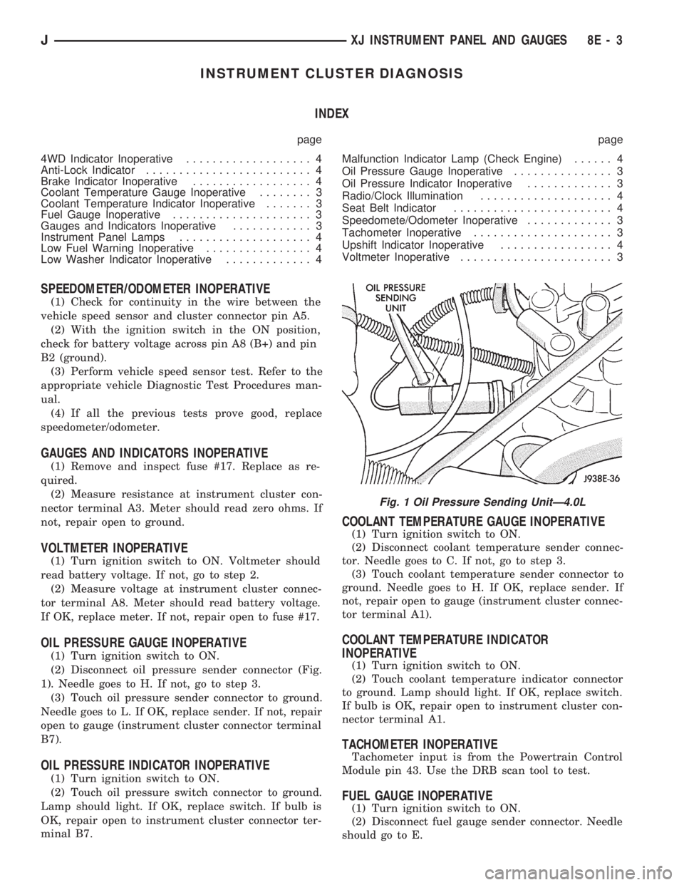
(2) Disconnect oil pressure sender connector (Fig.
1). Needle goes to H. If not, go to step 3.
(3) Touch oil pressure sender connector to ground.
Needle goes to L. If OK, replace sender. If not, repair
open to gauge (instrument cluster connector terminal
B7).
OIL PRESSURE INDICATOR INOPERATIVE
(1) Turn ignition switch to ON.
(2) Touch oil pressure switch connector to ground.
Lamp should light. If OK, replace switch. If bulb is
OK, repair open to instrument cluster connector ter-
minal B7.
COOLANT TEMPERATURE GAUGE INOPERATIVE
(1) Turn ignition switch to ON.
(2) Disconnect coolant temperature sender connec-
tor. Needle goes to C. If not, go to step 3.
(3) Touch coolant temperature sender connector to
ground. Needle goes to H. If OK, replace sender. If
not, repair open to gauge (instrument cluster connec-
tor terminal A1).
COOLANT TEMPERATURE INDICATOR
INOPERATIVE
(1) Turn ignition switch to ON.
(2) Touch coolant temperature indicator connector
to ground. Lamp should light. If OK, replace switch.
If bulb is OK, repair open to instrument cluster con-
nector terminal A1.
TACHOMETER INOPERATIVE
Tachometer input is from the Powertrain Control
Module pin 43. Use the DRB scan tool to test.
FUEL GAUGE INOPERATIVE
(1) Turn ignition switch to ON.
(2) Disconnect fuel gauge sender connector. Needle
should go to E.
Fig. 1 Oil Pressure Sending UnitÐ4.0L
JXJ INSTRUMENT PANEL AND GAUGES 8E - 3
Page 352 of 1784
INSTRUMENT CLUSTER SERVICE PROCEDURES
INDEX
page page
Gauge ReplacementÐInstrument Cluster Removed.. 5
Gear Selector Indicator ReplacementÐInstrument
Cluster Removed........................ 6
Instrument Cluster Replacement.............. 5
Instrument Panel Replacement (Fig. 9)......... 8
Printed Circuit ReplacementÐInstrumentCluster Removed........................ 6
Speedometer ReplacementÐInstrument
Cluster Removed........................ 5
Tachometer ReplacementÐInstrument
Cluster Removed........................ 5
INSTRUMENT CLUSTER REPLACEMENT
(1) Disconnect negative cable from battery.
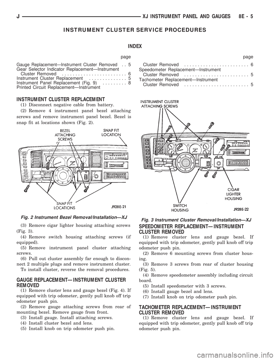
(2) Remove 4 instrument panel bezel attaching
screws and remove instrument panel bezel. Bezel is
snap fit at locations shown (Fig. 2).
(3) Remove cigar lighter housing attaching screws
(Fig. 3).
(4) Remove switch housing attaching screws (if
equipped).
(5) Remove instrument panel cluster attaching
screws.
(6) Pull out cluster assembly far enough to discon-
nect 2 multiple plugs and remove instrument cluster.
To install cluster, reverse the removal procedures.
GAUGE REPLACEMENTÐINSTRUMENT CLUSTER
REMOVED
(1) Remove cluster lens and gauge bezel (Fig. 4). If
equipped with trip odometer, gently pull knob off trip
odometer push pin.
(2) Remove gauge attaching screws from rear of
mounting bezel. Remove gauge from front.
(3) Install gauge. Install attaching screws.
(4) Install cluster bezel and lens.
(5) Install knob on trip odometer push pin.
SPEEDOMETER REPLACEMENTÐINSTRUMENT
CLUSTER REMOVED
(1) Remove cluster lens and gauge bezel. If
equipped with trip odometer, gently pull knob off trip
odometer push pin.
(2) Remove 6 mounting screws from cluster hous-
ing.
(3) Remove 3 screws from rear of cluster housing
(Fig. 5).
(4) Remove speedometer assembly including circuit
board.
(5) Install speedometer with 3 screws.
(6) Install gauge bezel and lens.
(7) Install knob on trip odometer push pin.
TACHOMETER REPLACEMENTÐINSTRUMENT
CLUSTER REMOVED
(1) Remove cluster lens and gauge bezel. If
equipped with trip odometer, gently pull knob off trip
odometer push pin.
Fig. 2 Instrument Bezel Removal/InstallationÐXJFig. 3 Instrument Cluster Removal/InstallationÐXJ
JXJ INSTRUMENT PANEL AND GAUGES 8E - 5
Page 353 of 1784
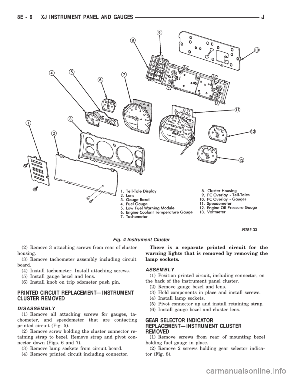
(2) Remove 3 attaching screws from rear of cluster
housing.
(3) Remove tachometer assembly including circuit
board.
(4) Install tachometer. Install attaching screws.
(5) Install gauge bezel and lens.
(6) Install knob on trip odometer push pin.
PRINTED CIRCUIT REPLACEMENTÐINSTRUMENT
CLUSTER REMOVED
DISASSEMBLY
(1) Remove all attaching screws for gauges, ta-
chometer, and speedometer that are contacting
printed circuit (Fig. 5).
(2) Remove screw holding the cluster connector re-
taining strap to bezel. Remove strap and pivot con-
nector down (Figs. 6 and 7).
(3) Remove lamp sockets from circuit board.
(4) Remove printed circuit including connector.There is a separate printed circuit for the
warning lights that is removed by removing the
lamp sockets.
ASSEMBLY
(1) Position printed circuit, including connector, on
the back of the instrument panel cluster.
(2) Remove gauge bezel and lens.
(3) Hold components in place and install screws.
(4) Install lamp sockets.
(5) Pivot connector up and install retaining strap.
(6) Install gauge bezel and cluster lens.
GEAR SELECTOR INDICATOR
REPLACEMENTÐINSTRUMENT CLUSTER
REMOVED
(1) Remove screws from rear of mounting bezel
holding fuel gauge in place.
(2) Remove 2 screws holding gear selector indica-
tor (Fig. 8).
Fig. 4 Instrument Cluster
8E - 6 XJ INSTRUMENT PANEL AND GAUGESJ
Page 361 of 1784

INSTRUMENT PANEL AND GAUGESÐYJE
CONTENTS
page page
GAUGE PACKAGE DIAGNOSIS............ 22
GAUGE PACKAGE GENERAL INFORMATION . 22
GAUGE PACKAGE SERVICE PROCEDURES . . 24
INSTRUMENT CLUSTER DIAGNOSIS....... 14INSTRUMENT CLUSTER GENERAL INFORMATION.14
INSTRUMENT CLUSTER SERVICE PROCEDURES.. 17
SPECIFICATIONS....................... 27
INSTRUMENT CLUSTER GENERAL INFORMATION
SPEEDOMETER/ODOMETER SYSTEM
The speedometer/odometer system consists of an
electric speedometer and pushbutton reset odometer
mounted in the cluster. The system also includes the
wire harness from the cluster to the vehicle speed
sensor at the transmission, and the adapter and pin-
ion in the transmission. A signal is sent from a
transmission mounted vehicle speed sensor to the
speedometer/odometer circuitry through the wiring
harness. Refer to Group 21 - Transmission for select-
ing the proper pinion, and selecting and indexing the
proper adapter.
TACHOMETER
The tachometer displays the engine speed (RPM).
With the engine running, the tachometer receives anengine speed signal from the Powertrain Control
Module pin 43 (values shown in Specifications chart).
INDICATOR LAMPS
The Brake, Upshift (2.5L with 5 speed transmis-
sion except California), and Malfunction Indicator
(Check Engine) lamps are located in the indicator
lamp panel above the steering column. The lamps
share a common battery feed connection through the
ignition switch and fuse #9.
The turn signals, high beam indicator, seat belt re-
minder, hazard lamp, master lighting and illumina-
tion bulbs are supplied battery voltage through
various switches and share a common ground.
INSTRUMENT CLUSTER DIAGNOSIS
INDEX
page page
Brake Indicator Lamp...................... 16
DiagnosingÐAll Lamps Out................. 16
Instrument Panel Illumination Lamps.......... 16
Malfunction Indicator Lamp (Check Engine)..... 16Seat Belt Reminder Lamp................... 16
Speedometer............................ 14
Tachometer............................. 14
Upshift Indicator Lamp..................... 16
SPEEDOMETER
(1) Raise vehicle.
(2) Disconnect the vehicle speed sensor connector.
(3) Connect a voltmeter between the black wire
pin of the connector and ground.
(4) Turn the ignition switch to the ON position.
(5) Check for approximately 5 volts. If OK, per-
form vehicle speed sensor test. Refer to the appropri-
ate Powertrain Diagnostic Procedures manual. If not
OK, continue with step 6.
(6) Turn ignition switch to OFF position.(7) Check continuity between vehicle speed sensor
connector and terminal 13 of instrument cluster con-
nector. If OK, replace speedometer. If not OK, repair
open circuit.
TACHOMETER
(1) Tachometer input is from the Powertrain Con-
trol Module (PCM) pin 43. Use the DRB scan tool to
perform actuator test. If OK, continue with step 2. If
not, replace PCM.
(2) Check for continuity between cluster connector
pin 12 and PCM pin 43. If OK, replace tachometer. If
not, repair open circuit.
8E - 14 YJ INSTRUMENT PANEL AND GAUGESJ
Page 1756 of 1784
ILLUMINATION LAMPS, INSTRUMENT
PANEL.............................8E-16
ILLUMINATION, RADIO/CLOCK.............8E-4
ILLUMINATION RELAY, RADIO.............8F-3
INDEX, GROUP; ELECTRICAL..............8A-1
INDEX, GROUP; INSTRUMENT PANEL
AND GAUGES........................8E-1
INDEX; WIRING DIAGRAMS XJ..........8W-149
INDEX; WIRING DIAGRAMS XJ-RHD.....8W-271
INDEX; WIRING DIAGRAMS YJ...........8W-73
INDEXES, WIRING DIAGRAM SHEETS......8W-1
INDICATOR, 4WD......................8E-22
INDICATOR, ANTI-LOCK..................8E-4
INDICATOR (BASE CLUSTER ONLY),
OPERATIONAL CHECK WITH BATTERY....8A-14
INDICATOR BEZEL REPLACEMENT.........8E-17
INDICATOR (CHECK ENGINE) LAMP FOR
DIAGNOSTIC TROUBLE CODES..........8A-19
INDICATOR INOPERATIVE, 4WD............8E-4
INDICATOR INOPERATIVE, BRAKE..........8E-4
INDICATOR INOPERATIVE, COOLANT
TEMPERATURE.......................8E-3
INDICATOR INOPERATIVE, LOW WASHER....8E-4
INDICATOR INOPERATIVE, OIL
PRESSURE..........................8E-3
INDICATOR INOPERATIVE, UPSHIFT........8E-4
INDICATOR LAMP, 4WD..................8E-2
INDICATOR LAMP, ANTI-LOCK BRAKE
SYSTEM (ABS).......................8E-2
INDICATOR LAMP, BRAKE; INSTRUMENT
PANEL AND GAUGESÐXJ...............8E-2
INDICATOR LAMP, BRAKE; INSTRUMENT
PANEL AND GAUGESÐYJ..............8E-16
INDICATOR LAMP (CHECK ENGINE),
MALFUNCTION; INSTRUMENT PANEL
AND GAUGESÐXJ................8E-2,8E-4
INDICATOR LAMP (CHECK ENGINE),
MALFUNCTION; INSTRUMENT PANEL
AND GAUGESÐYJ...................8E-16
INDICATOR LAMP, COOLANT
TEMPERATURE.......................8E-1
INDICATOR LAMPÐPCM OUTPUT,
MALFUNCTION......................14-26
INDICATOR LAMP, UPSHIFT; INSTRUMENT
PANEL AND GAUGESÐXJ...............8E-2
INDICATOR LAMP, UPSHIFT; INSTRUMENT
PANEL AND GAUGESÐYJ..............8E-16
INDICATOR LAMPS....................8E-14
INDICATOR, OIL PRESSURE...............8E-1
INDICATORÐPCM OUTPUT, SHIFT........14-26
INDICATOR REPLACEMENTÐGEAR
SELECTOR...........................8E-6
INDICATOR, SEAT BELT..................8E-4
INDICATOR (SRI) LAMP, SERVICE
REMINDER..........................25-1
INDICATORS INOPERATIVE, GAUGES.......8E-3
INDICATORS, TREAD WEAR...............22-3
INFLATION PRESSURE LABEL, TIRE.....INTRO.-3
INFLATION PRESSURES, TIRE.............22-2
INITIALIZATION, SYSTEM POWER-UP.......5-43
INJECTION (MFI)ÐCOMPONENT
DESCRIPTION/SYSTEM OPERATION,
MULTI-PORT FUEL...................14-17
INJECTION (MFI)ÐCOMPONENT
REMOVAL/INSTALLATION, MULTI-PORT
FUEL..............................14-54
INJECTION (MFI)ÐGENERAL DIAGNOSIS,
MULTI-PORT FUEL...................14-32
INJECTOR DIAGNOSISÐVEHICLE RUNS
ROUGH AND/OR HAS A MISS
...........14-49
INJECTOR, FUEL
.......................14-55
INJECTOR TEST
.......................14-48
INJECTORSÐPCM OUTPUT, FUEL
.........14-25
INNER AXLE SHAFT OIL SEAL
REPLACEMENT
.......................2-33
INNER SCUFF PLATE/COWL SIDE TRIM
PANELÐXJ VEHICLES, FRONT
.........23-114
INNER SPLASH SHIELDS, FENDER
.......23-147
INOPERATIVE, 4WD INDICATOR
............8E-4
INOPERATIVE, ALL GAUGES
.............8E-22
INOPERATIVE, BRAKE INDICATOR
..........8E-4
INOPERATIVE, COOLANT TEMPERATURE
GAUGE
..............................8E-3
INOPERATIVE, COOLANT TEMPERATURE
INDICATOR
..........................8E-3INOPERATIVE, DIAGNOSINGÐTURN
SIGNAL.............................8J-2
INOPERATIVE, DIAGNOSISÐHAZARD
LAMPS..........................8J-1,8J-2
INOPERATIVE, DIAGNOSISÐTURN
SIGNAL.............................8J-1
INOPERATIVE, FUEL GAUGE...............8E-3
INOPERATIVE, GAUGES AND INDICATORS....8E-3
INOPERATIVE, LOW FUEL WARNING........8E-4
INOPERATIVE, LOW WASHER INDICATOR....8E-4
INOPERATIVE, OIL PRESSURE GAUGE......8E-3
INOPERATIVE, OIL PRESSURE
INDICATOR..........................8E-3
INOPERATIVE, ONE GAUGE..............8E-22
INOPERATIVE, SPEEDOMETER/
ODOMETER..........................8E-3
INOPERATIVE, TACHOMETER..............8E-3
INOPERATIVE, UPSHIFT INDICATOR........8E-4
INOPERATIVE, VOLTMETER...............8E-3
INPUT, AIR CONDITIONING (A/C)
CONTROLSÐPCM....................14-19
INPUT, AUTOMATIC SHUT DOWN (ASD)
SENSEÐPCM.......................14-19
INPUT, BATTERY VOLTAGEÐPCM.........14-19
INPUT, BRAKE SWITCHÐPCM............14-20
INPUT, CAMSHAFT POSITION SENSORÐ
PCM...............................14-20
INPUT, CRANKSHAFT POSITION
SENSORÐPCM......................14-20
INPUT, DATA LINK CONNECTORÐPCM.....14-20
INPUT, ENGINE COOLANT TEMPERATURE
SENSORÐPCM......................14-21
INPUT, EXTENDED IDLE SWITCHÐPCM....14-21
INPUT, IGNITION CIRCUIT SENSEÐPCM....14-21
INPUT, INTAKE AIR TEMPERATURE
SENSORÐPCM......................14-20
INPUT, LOSS OF SENSOR.................5-3
INPUT, MANIFOLD ABSOLUTE
PRESSURE (MAP) SENSORÐPCM.......14-21
INPUT, OXYGEN (O2S) SENSORÐPCM.....14-22
INPUT, PARK/NEUTRAL SWITCHÐPCM.....14-22
INPUT, POWER STEERING PRESSURE
SWITCHÐPCM......................14-22
INPUT, SCI RECEIVEÐPCM..............14-22
INPUT, SENSOR RETURNÐPCM..........14-23
INPUT SIGNALS, WHEEL/TIRE SIZE..........5-3
INPUT, SPEED CONTROLÐPCM..........14-23
INPUT, THROTTLE POSITION SENSOR
(TPS)ÐPCM........................14-23
INPUT, VEHICLE SPEED SENSORÐPCM....14-23
INSERTÐXJ VEHICLES, QUARTER
WINDOW GLASS/REAR QUARTER
PLASTIC...........................23-80
INSIDE LATCH RELEASE AND LOCK
RODS, DOOR........................23-57
INSIDE RELEASE AND LOCK HANDLE,
FULL-METAL DOOR LATCH............23-175
INSPECTION AND ADJUSTMENT,
PRELIMINARY......................21-167
INSPECTION AND DIAGNOSIS CHARTS.......6-4
INSPECTION, CALIPER CLEANING..........5-28
INSPECTION, CLEANING....21-13,21-204,21-305
INSPECTION, COMPONENT................5-8
INSPECTION, GEAR CLEANING...........19-40
INSPECTION, PRE-ALIGNMENT.............2-6
INSPECTION, TORQUE CONVERTER
STATOR CLUTCH....................21-189
INSPECTION, TRANSMISSION CASE
CLEANING.........................21-118
INSPECTION, VALVE BODY DISASSEMBLY
. . 21-138
INSPECTION, VISUAL
...................14-32
INSPECTION/MEASUREMENTS, FRAME
.....13-10
INSPECTIONS, STARTER SYSTEM
DIAGNOSTIC
.........................8A-9
INSTALLATION, 30RH/32RH
TRANSMISSION REMOVAL
............21-108
INSTALLATION, ACCELERATION SENSOR
....5-52
INSTALLATION, AW-4 TRANSMISSION
REMOVAL AND
.....................21-189
INSTALLATIONÐAX 15, TRANSMISSION
....21-35
INSTALLATION, BRAKE PEDAL
.............5-66
INSTALLATION, BRAKELIGHT SWITCH
.......5-66
INSTALLATION, CALIPER
.................5-30
INSTALLATION, CLUTCH COVER AND
DISC
...............................6-10INSTALLATION, CLUTCH HYDRAULIC
LINKAGE............................6-12
INSTALLATION, CLUTCH PEDAL............6-15
INSTALLATION, DIFFERENTIAL; FRONT
SUSPENSION AND AXLE................2-43
INSTALLATION, DIFFERENTIAL; REAR
SUSPENSION AND AXLES...............3-24
INSTALLATION, DISC BRAKESHOE..........5-26
INSTALLATION, DRUM BRAKESHOE........5-34
INSTALLATION, FRONT WHEEL SENSOR.....5-49
INSTALLATION, MASTER CYLINDER....5-20,5-50
INSTALLATION, POWER BRAKE
BOOSTER.......................5-23,5-51
INSTALLATION, REAR WHEEL
SENSOR............................5-50
INSTALLATION, RING GEAR...............3-24
INSTALLATION, ROTOR..................5-30
INSTALLATION, TRANSFER CASE . . . 21-276,21-296
INSTALLATION, TRANSMISSION...........21-4
INSTALLATION, TRANSMISSION AND
CONVERTER.......................21-109
INSTALLATION, TRANSMISSION
AND TORQUE CONVERTER............21-190
INSTALLATION, TRANSMISSION VALVE
BODY.............................21-177
INSTALLATION, VALVE BODY............21-101
INSTALLATION, WHEEL..................22-6
INSTALLATION, WHEEL CYLINDER.........5-37
INSTALLATIONÐXJ, HCU.................5-54
INSTALLATION (XJ WITH FULL
CONSOLE), PARKING BRAKE LEVER.......5-60
INSTALLATION (XJ WITH MINI
CONSOLE), PARKING BRAKE LEVER.......5-58
INSTALLATION (XJ WITHOUT CONSOLE),
PARKING BRAKE LEVER................5-60
INSTALLATIONÐYJ, HCU.................5-54
INSTALLATION (YJ), PARKING BRAKE
PEDAL..............................5-61
INSTALLATION/ADJUSTMENT, IGNITION
SWITCH............................8D-31
INSTRUMENT CLUSTER.................8E-15
INSTRUMENT CLUSTER AND GAUGE
HOUSINGS
.........................23-190
INSTRUMENT CLUSTER BEZEL
.....23-91,23-191
INSTRUMENT CLUSTER BULB
REPLACEMENT
......................8E-19
INSTRUMENT CLUSTER DIAGNOSIS;
INSTRUMENT PANEL AND GAUGESÐ
XJ
.................................8E-3
INSTRUMENT CLUSTER DIAGNOSIS;
INSTRUMENT PANEL AND GAUGESÐ
YJ
................................8E-14
INSTRUMENT CLUSTER GAUGES;
INSTRUMENT PANEL AND GAUGESÐ
XJ
................................8E-13
INSTRUMENT CLUSTER GAUGES;
INSTRUMENT PANEL AND GAUGESÐ
YJ
................................8E-27
INSTRUMENT CLUSTER GENERAL
INFORMATION; INSTRUMENT PANEL
AND GAUGESÐXJ
....................8E-1
INSTRUMENT CLUSTER GENERAL
INFORMATION; INSTRUMENT PANEL
AND GAUGESÐYJ
...................8E-14
INSTRUMENT CLUSTER REPLACEMENT;
INSTRUMENT PANEL AND GAUGESÐ
XJ
.................................8E-5
INSTRUMENT CLUSTER REPLACEMENT;
INSTRUMENT PANEL AND GAUGESÐ
YJ
................................8E-17
INSTRUMENT CLUSTER SERVICE
PROCEDURES; INSTRUMENT PANEL
AND GAUGESÐXJ
....................8E-5
INSTRUMENT CLUSTER SERVICE
PROCEDURES; INSTRUMENT PANEL
AND GAUGESÐYJ
...................8E-17
INSTRUMENT CLUSTER/SWITCH/
LIGHTER/RADIO/HEVAC
................23-91
INSTRUMENT CLUSTERS
................8E-10
INSTRUMENT PANEL
.............23-93,23-190
INSTRUMENT PANEL AND GAUGESÐXJ
.....8E-1
INSTRUMENT PANEL AND GAUGESÐYJ
.....8E-1
INSTRUMENT PANEL COMPONENTS
......23-191
INSTRUMENT PANEL GAUGES
............8E-27
12 INDEXJ
Description Group-Page Description Group-Page Description Group-Page
Page 1765 of 1784
SNAP RING/THRUST WASHER/THRUST
PLATE SPECIFICATIONS, 30RH/32RH....21-322
SOFT TOP DOOR, HALF-METAL..........23-173
SOFT TOP SERVICE.............23-166,23-167
SOLENOID AND LATCH ASSEMBLY
REPLACEMENT.......................8P-6
SOLENOID VALVE OPERATION, HCU........5-43
SOLENOIDS, TRANSMISSION VALVE
BODY.............................21-175
SOLVENTS, BRAKE FLUID/LUBRICANTS/
CLEANING............................5-1
SOUND BAR REPLACEMENT..............8F-7
SOUND LEVELS, OPERATING...............5-3
SPACER BLOCKSÐTWO-DOOR
VEHICLES, FRONT DOOR..............23-60
SPARE TIRE/WHEEL HOLDDOWN AND
FLOOR BRACKETSÐXJ VEHICLES......23-128
SPARE/WHEEL TIRE CARRIER,
EXTERNAL.........................23-172
SPARK PLUG CABLE RESISTANCE........8D-18
SPARK PLUG SECONDARY CABLES . . 8D-17,8D-29
SPARK PLUGS; IGNITION SYSTEMS . 8D-16,8D-28,
8D-33
SPARK PLUGS; LUBRICATION AND
MAINTENANCE.......................0-18
SPEAKER/COURTESY LAMP SUPPORT
BRACKET,I/P TWEETER................23-95
SPEAKERS, RADIO..................8F-4,8F-6
SPECIFICATION NOTATIONS...........INTRO.-8
SPECIFICATIONS, 2.5L STARTER MOTOR . . . 8B-11
SPECIFICATIONS, 30RH/32RH GENERAL . . . 21-322
SPECIFICATIONS, 30RH/32RH PRESSURE
TEST.............................21-323
SPECIFICATIONS, 30RH/32RH SNAP RING/
THRUST WASHER/THRUST PLATE......21-322
SPECIFICATIONS, 30RH/32RH TORQUE....21-320
SPECIFICATIONSÐACCESSORIES,
TORQUE...........................23-208
SPECIFICATIONS AND BAND
ADJUSTMENTS......................21-66
SPECIFICATIONS, AW-4 GENERAL........21-324
SPECIFICATIONS, AW-4 RETAINER AND
PISTON...........................21-327
SPECIFICATIONS, AW-4 TORQUE.........21-331
SPECIFICATIONS, AXLE; FRONT
SUSPENSION AND AXLE................2-46
SPECIFICATIONS, AXLE; REAR SUSPENSION
AND AXLES......................3-28,3-44
SPECIFICATIONS, BATTERY TORQUE.......8B-10
SPECIFICATIONS, BELT TENSION...........7-34
SPECIFICATIONS, BODY LUBRICANT........0-35
SPECIFICATIONS, BRAKE TORQUE..........5-67
SPECIFICATIONS; BRAKES................5-67
SPECIFICATIONS; COOLING SYSTEM........7-38
SPECIFICATIONS; ELECTRICAL............8A-8
SPECIFICATIONS, ENGINE....9-48,9-49,9-88,9-89,
9-47,9-87
SPECIFICATIONS; ENGINES...........9-47,9-87
SPECIFICATIONS; FUEL SYSTEM..........14-62
SPECIFICATIONS, GENERATOR...........8B-12
SPECIFICATIONS; IGNITION SYSTEMS.....8D-33
SPECIFICATIONS; INSTRUMENT PANEL
AND GAUGESÐXJ...................8E-13
SPECIFICATIONS; INSTRUMENT PANEL
AND GAUGESÐYJ...................8E-27
SPECIFICATIONS; INTRODUCTION......INTRO.-8
SPECIFICATIONS; LAMPS................8L-23
SPECIFICATIONS, LUBRICANT; FRONT
SUSPENSION AND AXLE................2-20
SPECIFICATIONS, LUBRICANT; REAR
SUSPENSION AND AXLES...........3-11,3-30
SPECIFICATIONS, MANUAL STEERING
GEAR..............................19-44
SPECIFICATIONS, NP231/NP242 TORQUE . . 21-331
SPECIFICATIONS, OUTPUT VOLTAGE.......8B-12
SPECIFICATIONS, POWER STEERING
GEAR..............................19-34
SPECIFICATIONS, PUMP OPERATING.......19-3
SPECIFICATIONS, RUNOUT...............16-4
SPECIFICATIONS, STARTER MOTOR
TORQUE...........................8B-11
SPECIFICATIONS, TESTING
..............8B-11
SPECIFICATIONS, TORQUE; BATTERY/
STARTER/GENERATOR SERVICE
.........8B-12
SPECIFICATIONS, TORQUE; CLUTCH
........6-17
SPECIFICATIONS, TORQUE; ELECTRICAL
.....8A-8SPECIFICATIONS, TORQUE; ENGINES . . . 9-49,9-89
SPECIFICATIONS, TORQUE; EXHAUST
SYSTEM AND INTAKE MANIFOLD........11-10
SPECIFICATIONS, TORQUE; FRONT
SUSPENSION AND AXLE................2-47
SPECIFICATIONS, TORQUE; HEATING
AND AIR CONDITIONING...............24-45
SPECIFICATIONS, TORQUE; HORNS........8G-3
SPECIFICATIONS, TORQUE;
INTRODUCTION...................INTRO.-8
SPECIFICATIONS, TORQUE; PROPELLER
SHAFTS............................16-14
SPECIFICATIONS, TORQUE; REAR
SUSPENSION AND AXLES...............3-50
SPECIFICATIONS, TORQUE; STEERING.....19-73
SPECIFICATIONS, TRANSMISSION/
TRANSFER CASE....................21-320
SPECIFICATIONS; WHEELS AND TIRES.....22-11
SPECIFICATIONSÐXJ VEHICLES,
ALIGNMENT...........................2-9
SPECIFICATIONSÐYJ VEHICLES,
ALIGNMENT...........................2-9
SPEED CONTROLÐPCM INPUT...........14-23
SPEED CONTROLÐPCM OUTPUT.........14-27
SPEED CONTROL SERVO REPLACEMENT....8H-9
SPEED CONTROL SWITCH REPLACEMENT . . . 8H-9
SPEED CONTROL SWITCH TEST, STOP
LAMP..............................8H-7
SPEED CONTROL SWITCH (TURN
SIGNAL LEVER) TEST..................8H-7
SPEED CONTROL SYSTEM ELECTRICAL
TESTS, VEHICLE......................8H-5
SPEED CONTROL SYSTEM, VEHICLE........8A-1
SPEED SENSOR......................21-182
SPEED SENSOR AIR GAP, REAR............5-3
SPEED SENSOR OPERATION, WHEEL.......5-45
SPEED SENSORÐPCM INPUT, VEHICLE....14-23
SPEED SENSOR ROTORÐSPEEDOMETER
DRIVE GEAR.......................21-183
SPEED SENSOR TEST, VEHICLE; FUEL
SYSTEM............................14-45
SPEED SENSOR TEST, VEHICLE;
VEHICLE SPEED CONTROL SYSTEM......8H-5
SPEED SENSOR, VEHICLE...............14-60
SPEED SENSORS, WHEEL................5-41
SPEEDOMETER........................8E-14
SPEEDOMETER REPLACEMENT...........8E-17
SPEEDOMETER REPLACEMENTÐ
INSTRUMENT CLUSTER REMOVED.......8E-5
SPEEDOMETER SERVICE.........21-103,21-275,
21-296
SPEEDOMETER/ODOMETER INOPERATIVE . . . 8E-3
SPEEDOMETER/ODOMETER SYSTEM;
INSTRUMENT PANEL AND GAUGESÐXJ . . . 8E-2
SPEEDOMETER/ODOMETER SYSTEM;
INSTRUMENT PANEL AND GAUGESÐYJ . . 8E-14
SPLASH APRONS, FENDER.............23-147
SPLASH LINERS, WHEELHOUSE.........23-146
SPLASH SHIELD, GENERATOR............13-14
SPLASH SHIELDÐXJ VEHICLES, FUEL
FILLER HOSE........................23-86
SPLASH SHIELDS, FENDER INNER.......23-147
SPLICE LOCATIONS; WIRING DIAGRAMS . . . 8W-2,
8W-53
SPLICE LOCATIONS, XJ................8W-59
SPLICE LOCATIONS, XJ RHD............8W-67
SPLICE LOCATIONS, YJ................8W-53
SPORT BAR.........................23-171
SPRING AND SHOCK DIAGNOSIS;
FRONT SUSPENSION AND AXLE......2-12,2-14
SPRING AND SHOCK DIAGNOSIS; REAR
SUSPENSION AND AXLES.............3-3,3-5
SPRING, COIL.........................2-13
SPRING EYE BUSHING REPLACEMENT,
FRONT..............................2-15
SPRING EYE BUSHING REPLACEMENT,
REAR.............................3-4,3-6
SPRING IDENTIFICATION, AW-4..........21-330
SPRING, LEAF; FRONT...................2-14
SPRING, LEAF; REAR..................3-3,3-6
SPRINGS, ACCUMULATOR PISTONS......21-179
SPRINGS AND OIL SEALS, VALVE......9-21,9-62
SPRINGS, VALVES AND VALVE
........9-22,9-63
SPROCKETS, TIMING CHAIN
..........9-28,9-68
STABILIZER BAR
...................2-10,2-14
STABILIZER BARÐXJ VEHICLES
............3-4STALL TEST, ACTUATOR MOTOR...........8P-6
STALL TEST, CONVERTER...............21-72
STALL TEST, TORQUE CONVERTER.......21-169
STANDARD MASTER CYLINDER...........5-20
STANDARD TORQUE VALUES..........INTRO.-9
STARTER CONTROL CIRCUIT TESTS.......8A-11
STARTER FEED CIRCUIT TESTS -
(VOLTAGE DROP METHOD)..............8A-9
STARTER GENERAL INFORMATION, 2.5L....8B-4
STARTER GENERAL INFORMATION, 4.0L....8B-6
STARTER MOTOR NOISE DIAGNOSIS, 2.5L . . 8A-13
STARTER MOTOR RELAY TEST...........14-48
STARTER MOTOR REMOVAL/
INSTALLATION, 2.5L...................8B-5
STARTER MOTOR
REMOVAL/INSTALLATION, 4.0L..........8B-6
STARTER MOTOR SERVICE PROCEDURES,
ENGINE.............................8B-4
STARTER MOTOR SPECIFICATIONS, 2.5L . . . 8B-11
STARTER MOTOR TEST PROCEDURES
ON VEHICLE, ENGINE..................8A-9
STARTER MOTOR TORQUE
SPECIFICATIONS.....................8B-11
STARTER RELAY CONNECTIONS..........8A-12
STARTER RELAY REPLACEMENT...........8B-4
STARTER SYSTEM DIAGNOSTIC
INSPECTIONS........................8A-9
STARTING, JUMP........................0-7
STARTING SYSTEM COLD CRANKING TEST . . 8A-9
STARTING SYSTEM DIAGNOSIS..........8A-10
STATOR CLUTCH INSPECTION, TORQUE
CONVERTER.......................21-189
STEERING COLUMN GENERAL SERVICE....19-45
STEERING COLUMN, NON-TILT
...........19-50
STEERING COLUMN, TILT
...............19-59
STEERING COLUMNÐXJ
................19-73
STEERING COLUMNÐYJ
................19-73
STEERING DAMPENER
.............19-15,19-18
STEERING GEAR ADJUSTMENTS
..........19-22
STEERING GEAR, MANUAL
.........19-35,19-73
STEERING GEAR, POWER
...............19-73
STEERING GEAR, RECIRCULATING BALL
POWER
............................19-19
STEERING GEAR REPLACEMENT
.....19-21,19-43
STEERING GEAR SPECIFICATIONS,
MANUAL
...........................19-44
STEERING GEAR SPECIFICATIONS,
POWER
............................19-34
STEERING GEARÐYJ VEHICLES,
MANUAL
............................0-32
STEERING GEARS, RECIRCULATING-
BALL POWER
.......................19-69
STEERING KNUCKLE AND BALL STUDS
.....2-30
STEERING LINKAGE AND BALL STUDS
......0-30
STEERING LINKAGEÐXJ
...........19-14,19-73
STEERING LINKAGEÐYJ
...........19-17,19-73
STEERING PRESSURE SWITCHÐ2.5L
ENGINE ONLY, POWER
................14-58
STEERING PRESSURE SWITCHÐPCM
INPUT, POWER
......................14-22
STEERING PUMPÐINITIAL OPERATION,
POWER
............................19-13
STEERING PUMP, POWER
......19-9,19-69,19-73
STEERING RESPONSE
....................5-3
STEERING RHD
.......................19-69
STEERING SYSTEM COMPONENTS
.........19-1
STEERING SYSTEM DIAGNOSIS, MANUAL
. . 19-36
STEERING SYSTEM DIAGNOSIS, POWER
....19-3,
19-4,19-5,19-6,19-7
STEERING SYSTEM DIAGNOSIS,
SUSPENSION
..........................2-7
STEERING SYSTEM, POWER
..............0-31
STEERING WHEEL
.....................19-45
STEP MOULDING, BODY SIDE
...........23-145
STONE CHIP PROTECTION
..............23-201
STOP LAMP (CHMSL)ÐXJ, CENTER
HIGH MOUNTED
.....................8L-10
STOP LAMP (CHMSL)ÐYJ, CENTER
HIGH MOUNTED
.....................8L-11
STOP LAMP SPEED CONTROL SWITCH
TEST
...............................8H-7
STORAGEÐXJ VEHICLES, JACK
.........23-127
JINDEX21
Description Group-Page Description Group-Page Description Group-Page