1994 JEEP CHEROKEE remote start
[x] Cancel search: remote startPage 344 of 1784

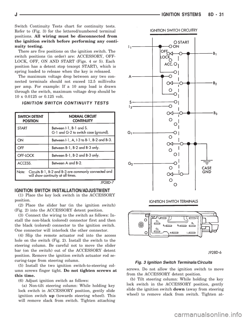
Switch Continuity Tests chart for continuity tests.
Refer to (Fig. 3) for the lettered/numbered terminal
positions.All wiring must be disconnected from
the ignition switch before performing any conti-
nuity testing.
There are five positions on the ignition switch. The
switch positions (in order) are: ACCESSORY, OFF-
LOCK, OFF, ON AND START (Figs. 4 or 5). Each
position has a detent stop (except START), which is
spring loaded to release when the key is released.
The maximum voltage drop between any two con-
nected terminals should not exceed 12.5 millivolts
per amp. For example: If a 10 amp load is drawn
through the switch, maximum voltage drop should be
10 x 0.0125 or 0.125 volt.
IGNITION SWITCH INSTALLATION/ADJUSTMENT
(1) Place the key lock switch in the ACCESSORY
position.
(2) Place the slider bar (in the ignition switch)
(Fig. 2) into the ACCESSORY detent position.
(3) Connect the wiring to the switch as follows: In-
stall the non-black (colored) connector first and then
the black (colored) connector to the ignition switch.
One connector will interlock the other connector.
(4) Slip the remote actuator rod into the access
hole on the switch (Fig. 2). Install the switch to the
steering column. Be careful not to move the slider
bar (on the switch) out of the ACCESSORY detent
position. Remove the ignition switch actuator rod se-
curing-tape from steering column.
(5) Install the two ignition switch-to-steering col-
umn screws finger tight.Do not tighten screws at
this time.
(6) Adjust ignition switch as follows:
(a) Non-tilt steering column: While holding key
lock switch in ACCESSORY position, gently slide
ignition switchup(towards steering wheel). This
will remove slack from switch. Tighten attachingscrews. Do not allow the ignition switch to move
from the ACCESSORY detent position.
(b) Tilt steering column: While holding the key
lock switch in the ACCESSORY position, gently
slide the ignition switchdown(away from steering
wheel) to remove slack from switch. Tighten at-
IGNITION SWITCH CONTINUITY TESTS
Fig. 3 Ignition Switch Terminals/Circuits
JIGNITION SYSTEMS 8D - 31
Page 461 of 1784

ACTUATOR MOTOR STALL TEST
To test the actuator motor, connect an ammeter in
series with the motor and operate the door switch.
Replace the actuator motor if current draw exceeds 8
amps at room temperature or if the actuator does not
complete its travel in less than one second. Refer to
Solenoid and Latch Assembly Replacement procedures.
SWITCH REPLACEMENT
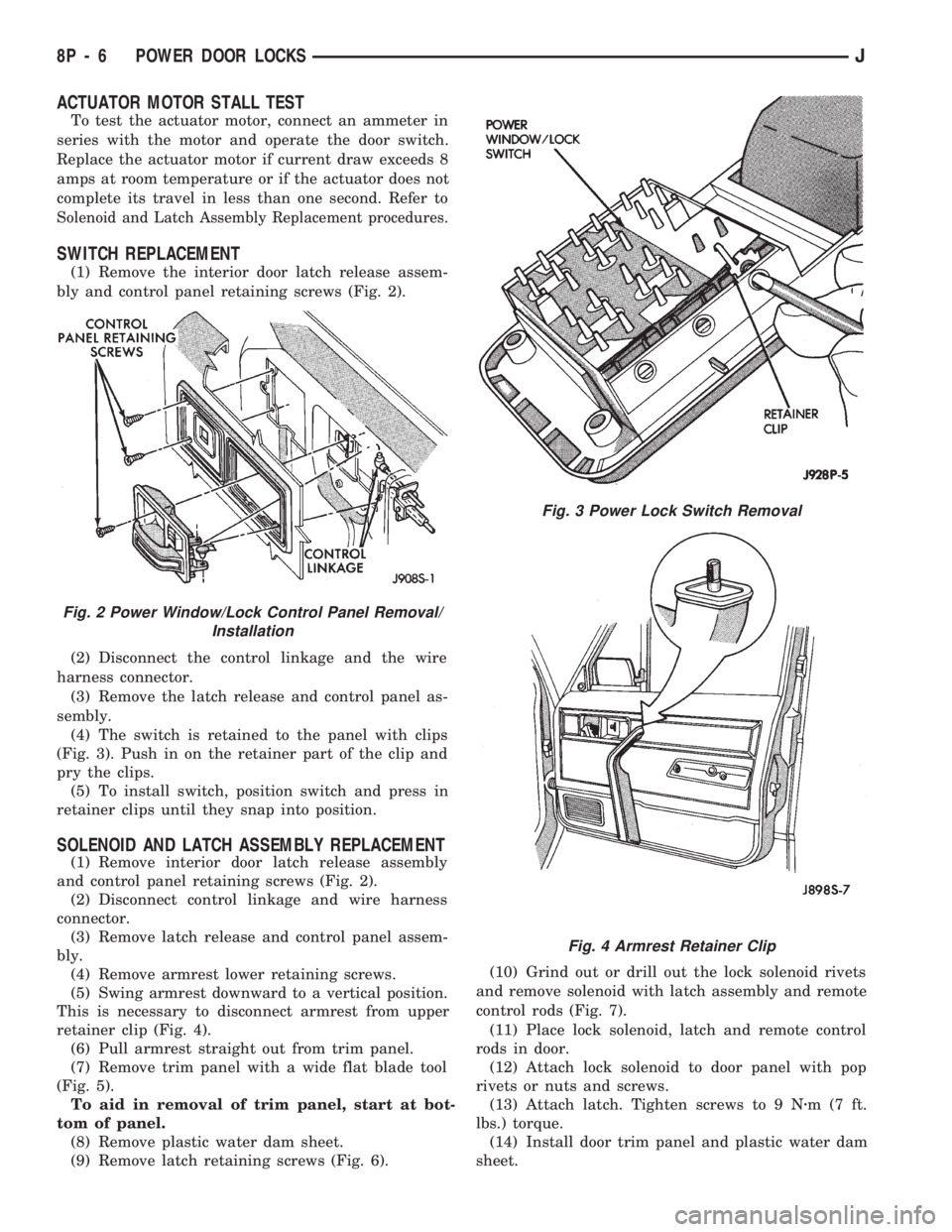
(1) Remove the interior door latch release assem-
bly and control panel retaining screws (Fig. 2).
(2) Disconnect the control linkage and the wire
harness connector.
(3) Remove the latch release and control panel as-
sembly.
(4) The switch is retained to the panel with clips
(Fig. 3). Push in on the retainer part of the clip and
pry the clips.
(5) To install switch, position switch and press in
retainer clips until they snap into position.
SOLENOID AND LATCH ASSEMBLY REPLACEMENT
(1) Remove interior door latch release assembly
and control panel retaining screws (Fig. 2).
(2) Disconnect control linkage and wire harness
connector.
(3) Remove latch release and control panel assem-
bly.
(4) Remove armrest lower retaining screws.
(5) Swing armrest downward to a vertical position.
This is necessary to disconnect armrest from upper
retainer clip (Fig. 4).
(6) Pull armrest straight out from trim panel.
(7) Remove trim panel with a wide flat blade tool
(Fig. 5).
To aid in removal of trim panel, start at bot-
tom of panel.
(8) Remove plastic water dam sheet.
(9) Remove latch retaining screws (Fig. 6).(10) Grind out or drill out the lock solenoid rivets
and remove solenoid with latch assembly and remote
control rods (Fig. 7).
(11) Place lock solenoid, latch and remote control
rods in door.
(12) Attach lock solenoid to door panel with pop
rivets or nuts and screws.
(13) Attach latch. Tighten screws to 9 Nzm(7ft.
lbs.) torque.
(14) Install door trim panel and plastic water dam
sheet.
Fig. 3 Power Lock Switch Removal
Fig. 2 Power Window/Lock Control Panel Removal/
Installation
Fig. 4 Armrest Retainer Clip
8P - 6 POWER DOOR LOCKSJ
Page 645 of 1784

Wiring Diagram Name Sheet Number
License Lamp...........................91,95
Low Washer Indicator Lamp..................57,58
Malfunction Indicator Lamp..................57,58
Maintenance Required Indicator Lamp...........57,58
Park Brake Indicator Lamp.....................58
Reading Lamp.............................51
Rear Wiper/Wash Switch Lamp..................47
Right Back-Up Lamp.......................92,96
Right Courtesy Lamp........................49
Right Fog Lamp............................40
Right Headlamp............................40
Right Park/Turn Signal Lamp...................40
Right Side Marker Lamp (Front).................40
Right Side Marker (Rear)....................92,96
Right Tail/Stop Lamp......................92,96
Right Turn Indicator Lamp.................59,60,61
Right Turn Lamp (Amber)...................92,96
Right Vanity Lamp..........................51
Seat Belt Warning Indicator Lamp..............57,58
Transfer Case Lamp.........................48
Transmission Range Switch Lamp................48
Underhood Lamp...........................34
Upshift Indicator Lamp.....................57,58
Vanity Lamps...........................51,53
L.C.D. Illumination Relay........................52
Left Front Door Connector And Door Lock Switch
Function Chart.............................87
Left Front Door Connector and Widow Lift Switch
Function Chart.............................87
Left Front Door Jamb Switch.....................75
Left Front Door Lock Motor......................86
Left Front Door Speaker........................71
Left Front Wheel Sensor........................29
Left Instrument Panel Speaker....................71
Left Liftgate Speaker..........................72
Left Power Seat Motor Assembly..................77
Left Power Seat Switch........................77
Left Rear Door Connector and Window Lift Switch
Function Chart.............................88
Left Rear Door Jamb Switch.....................75
Left Rear Door Window Switch...................82
Left Rear Wheel Sensor........................29
Left Turn Relay..............................97
Liftgate Switch..............................76
Liftgate Lock motor...........................86
Lo-Line Instrument Cluster Printed Circuit Board........60
Low Fuel Warning Module...................59,60,61
Low Washer Indicator Lamp...................57,58
Main Body Connectors........................112
Maintenance Required Indicator Lamp.............57,58
Malfunction Indicator Lamp....................57,58
Map Sensor..............................14,19
Modules
Anti-Lock Brake System Module.........29,30,31,32,33
Chime Module.............................74
Daytime Running Lamp Module.................38
Headlamp Delay Module......................43
Intermittent Wiper Module.....................64Wiring Diagram Name Sheet Number
Low Fuel Warning Module.................59,60,61
Powertrain Control Module. . . .11,12,13,14,15,16,17, 18,19,
20,21,22,23,35,36,45,55,69
Remote Keyless Entry Module...................28
Transmission Control Module.................25,26
Motors
ABS Pump Motor...........................30
A/C Heater Blower Motor......................70
Engine Starter Motor........................7,8
Front Wiper Motor........................63,64
Heater Blower Motor.........................68
Idle Air Control Motor......................15,22
Left Front Door Lock Motor....................86
Left Front Door Window Motor..................81
Left Power Mirror..........................73
Left Power Seat Motor Assembly................77
Left Rear Door Lock Motor....................86
Left Rear Door Window Motor..................82
Liftgate Lock Motor.........................86
Radiator Fan Motor.........................23
Rear Wiper Motor..........................65
Right Front Door Lock Motor...................86
Right Front Door Window Motor.................81
Right Power Mirror.........................73
Right Rear Door Lock Motor...................86
Right Rear Door Window Motor.................82
Oil Pressure Switch...........................24
Overhead Console System.....................53,54
Ambient Temperature Sensor...................53
Overhead Console..........................53
Vanity Lamps.............................53
Park Brake Switch............................67
Park Brake Indicator Lamp......................58
Parking Brake Switch..........................67
Park Lamp Relay.............................39
Park/Neutral Position Switch......................7
Pedal Travel Sensor...........................30
Power Distribution Center....................1,2,3,4
Power Distribution Center Application Chart............4
Power Distribution Center Identification...............3
Power Door Locks......................83,84,85,86
Left Door Lock Switch.......................85
Left Front Door Lock Motor....................86
Left Rear Door Lock Motor....................86
Liftgate Lock Motor.........................86
Power Door Lock Relay.......................83
Power Door Unlock Relay.....................83
Right Door Lock Switch......................85
Right Front Door Lock Motor...................86
Right Rear Door Lock Motor...................86
Power Door Lock Relay........................83
Power Door Unlock Relay.......................83
Power Mirror Connector.......................110
Power Mirror Connector and Switch Function Chart......88
Power Mirror Switch Assembly...................73
Power Mirror System..........................73
Left Power Mirror..........................73
Power Mirror Switch Assembly..................73
8W - 152 WIRING DIAGRAMSJ
Page 646 of 1784

Wiring Diagram Name Sheet Number
Right Power Mirror.........................73
Power Mirrors.............................73
Power Seat..............................77,78
Left Power Seat Motor Assembly................77
Left Power Seat Switch.......................78
Power Steering Pressure Switch...................15
Powertrain Control Module......11,12,13,14,15,16,17,18,19,
20,21,22,23,35,36,45,55,69
Powertrain Control Module (PCM) Connector..........111
Power Windows.......................79,80,81,82
Left Front Door Window Motor..................81
Left Rear Door Window Motor..................82
Left Rear Door Window Switch..................82
Power Window Switch.......................79
Right Front Door Window Switch................81
Right Front Door Window Motor.................81
Right Rear Door Window Motor.................82
Right Rear Door Window Switch.................82
Power Window Switch.........................79
Printed Circuit Boards.................57,58,59,60,61
Pumps
Front Washer...........................63,64
Rear Washer..............................65
Radiator Fan Motor...........................23
Radio....................................71
Antenna Mast.............................71
Left Front Door Speaker......................71
Left Instrument Panel Speaker..................71
Left Liftgate Speaker.........................72
Right Front Door Speaker.....................72
Right Instrument Panel Speaker.................72
Right Liftgate Speaker........................72
Reading Lamps..............................51
Rear Lighting...................91,92,93,94,95,96,97
Left Back-Up Lamp........................91,93
Left Side Marker Lamp (Rear)................91,93
Left Tail/Stop Lamp.......................91,93
Left Turn Lamp (Amber)....................91,93
Left Turn Relay............................97
License Lamp...........................91,95
Right Back-Up Lamp.......................92,96
Right Side Marker Lamp (Rear)...............92,96
Right Tail/Stop Lamp......................92,96
Right Turn Lamp (Amber)...................92,96
Right Turn Relay...........................97
Stop Lamp Relay...........................97
Trailer Tow Connector........................93
Trailer Tow In-Line Circuit Breaker................97
Rear Lighting With Trailer Tow............93,94,95,96,97
Rear Lighting Without Trailer Tow................91,92
Rear Washer Pump...........................65
Rear Wiper Motor............................65
Rear Wiper/Washer Motor.......................65
Rear Washer Pump...........................65
Rear Wiper Motor............................65
Rear Wiper/Washer Switch......................65
Rear Wiper/Washer Switch Lamp..................47
Reed Switch................................26Wiring Diagram Name Sheet Number
Relays
ABS #1 Relay............................3,31
ABS #2 Relay............................3,31
A/C Compressor Clutch Relay..................3,69
Automatic Shut Down Relay.................3,12,17
Cooling Fan Relay...........................3
EMCC Relay.............................3,27
Engine Starter Relay.......................3,7,8
Fan Control Relay...........................23
Fuel Pump Relay........................3,12,17
Heated Rear Window Relay....................66
High Beam Relay...........................40
Horn Relay...............................34
L.C.D. Illumination Relay......................52
Left Turn Relay............................97
Park Lamp Relay...........................39
Power Door Lock Relay.......................83
Power Door Unlock Relay.....................83
Right Turn Relay...........................97
Stop Lamp Relay...........................97
Relay Center Identification......................113
Remote Keyless Entry System....................28
Remote Keyless Entry Module...................28
Remote Keyless Entry Module Connector...........114
Resistor,Ballast..............................39
Resistor,Blower..............................68
Right Front Door Jamb Switch....................76
Right Front Door Speaker.......................72
Right Front Door Window Switch..................81
Right Front Wheel Sensor.......................29
Right Front Door Connector and Door Lock Switch
Function Chart.............................87
Right Front Door Lock Motor.....................86
Right Instrument Panel Speaker...................72
Right Liftgate Speaker.........................72
Right Front Door Window Connector and Window Lift
Switch Function Chart........................87
Right Rear Door Jamb Switch....................76
Right Rear Door Window Connector and Window Lift
Function Chart.............................88
Right Rear Wheel Sensor.......................29
Right Turn Relay.............................97
Seat Belt Switch.............................74
Seat Belt Warning Indicator Lamp................57,58
Sensors
Ambient Temperature Sensor...................53
Camshaft Position Sensor...................11,20
Crankshaft Position Sensor...................11,20
Engine Coolant Temperature Sensor.............14,19
G Sensor................................30
Heated Oxygen Sensor.....................13,21
Intake Air Temperature Sensor................14,19
Left Front Wheel Sensor......................29
Left Rear Wheel Sensor.......................29
MAP Sensor............................14,19
Pedal Travel Sensor.........................30
Right Front Wheel Sensor.....................29
Right Rear Wheel Sensor......................29
JWIRING DIAGRAMS 8W - 153