1994 JEEP CHEROKEE radio antenna
[x] Cancel search: radio antennaPage 376 of 1784
AUDIO SYSTEMS
CONTENTS
page page
GENERAL INFORMATION.................. 1
RADIO ANTENNA........................ 8XJ SERVICE PROCEDURES................ 4
YJ SERVICE PROCEDURES................ 6
GENERAL INFORMATION
DESCRIPTION
Each radio receives ignition feed from an ignition
switch controlled fuse. There is an additional in-line
fuse in the back of the radio chassis. The in-line fuse
will blow in the event an internal short occurs.
The electronically tuned radio (ETR)/cassette
models protect the vehicle from a radio failure
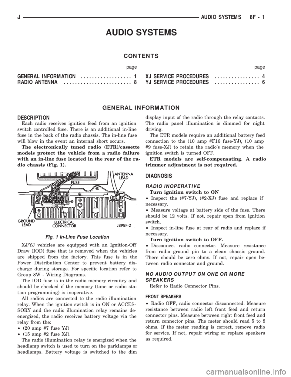
with an in-line fuse located in the rear of the ra-
dio chassis (Fig. 1).
XJ/YJ vehicles are equipped with an Ignition-Off
Draw (IOD) fuse that is removed when the vehicles
are shipped from the factory. This fuse is in the
Power Distribution Center to prevent battery dis-
charge during storage. For specific location refer to
Group 8W - Wiring Diagrams.
The IOD fuse is in the radio memory circuitry and
should be checked if the memory (time or radio sta-
tion programming) is inoperative.
All radios are connected to the radio illumination
relay. When the ignition switch is in ON or ACCES-
SORY and the radio illumination relay remains de-
energized, the radio receives battery voltage via the
relay from the:
²(20 amp #7 fuse YJ)
²(15 amp #2 fuse XJ).
The radio illumination relay is energized when the
headlamp switch is used to turn on the parklamps or
headlamps. Battery voltage is switched to the dimdisplay input of the radio through the relay contacts.
The radio panel illumination is dimmed for night
driving.
The ETR models require an additional battery feed
connection to the (10 amp #F16 fuse-YJ), (10 amp
#9 fuse-XJ) to retain the radio's memory when the
ignition switch is turned OFF.
ETR models are self-compensating. A radio
trimmer adjustment is not required.
DIAGNOSIS
RADIO INOPERATIVE
Turn ignition switch to ON
²Inspect the (#7-YJ), (#2-XJ) fuse and replace if
necessary.
²Measure voltage at battery side of the fuse. There
should be 12 volts. If not, repair open from ignition
switch.
²Inspect in-line fuse at rear of radio and replace if
necessary.
Turn ignition switch to OFF.
²Disconnect radio connector. Measure resistance
from radio ground pin to a clean chassis ground.
There should be zero ohms. If not, repair open be-
tween radio connector and ground.
NO AUDIO OUTPUT ON ONE OR MORE
SPEAKERS
Refer to Radio Connector Pins.
FRONT SPEAKERS
²Radio OFF, radio connector disconnected. Measure
resistance between radio left front feed and return
connector pins. Measure between right front feed and
return connector pins. The meter should read 5 to 8
ohms. If the meter reading is correct, remove radio
for service. If not, repair wiring or replace speakers
as required.
Fig. 1 In-Line Fuse Location
JAUDIO SYSTEMS 8F - 1
Page 377 of 1784
REAR SPEAKERS
²Radio OFF, radio connector disconnected. Measure
resistance between radio left rear feed and return
connector pins. Measure between right rear feed and
return connector pins. The meter should read 5 to 8
ohms. If meter reading is correct remove radio for
service. If not, repair wiring or replace speakers as
required.
DISTORTED AUDIO OUTPUT ON ONE OR
MORE SPEAKERS
²With the radio ON, substitute known good speaker
or speakers. If the sound is still distorted, remove ra-
dio for service.
WEAK OR NO RECEPTION; NO AUDIO
OUTPUT; BACKGROUND NOISE PRESENT
Ignition switch in ON, radio ON.
²Inspect antenna cable and connector at radio and
tighten or repair as necessary.
²Unplug coax cable and connectors from radio. Mea-
sure resistance from center conductor to coaxial
shield. The meter should read infinite resistance
(open). If it does not, replace antenna assembly.
²Measure resistance of antenna mast to tip of cen-
ter conductor at radio end of cable. The meter should
read 0 to 0.5 ohms. If it does not, replace lead-in ca-
ble or antenna assembly.
²Measure resistance from coaxial shield to chassis
ground (vehicle body). The meter should read zero
ohms. If it does not, ground antenna base to vehicle
body, or replace antenna assembly as required
For all problems with no or low audio output
not resolved by these tests, remove radio for ser-
vice.
MEMORY DOES NOT OPERATE
²Inspect (F16 in Power Distribution Center-YJ),
(#9 in Fuse Panel-XJ) fuse and replace if necessary.
²Measure voltage at battery side of previously ref-
erenced fuse. There should be 12 volts at battery side
of fuse. If not, check the Maxi fuse.
Refer to Group 8W - Wiring Diagrams.
²Measure voltage at radio connector pin 4. There
should be 12 volts. If meter reading is correct, re-
move radio for service. If not, repair open from fuse.
RADIO DISPLAY ILLUMINATION (PARKLAMPS
AND HEADLAMPS OPERATING NORMALLY)
Headlamp switch OFF, radio ON.
²Measure voltage at radio connector pin 10. There
should be 12 volts. If not, go to next step. If OK, re-
move radio for repair by authorized outlet.
²Measure voltage at illumination relay pin 3. There
should be 12 volts. If 12 volts present, replace illumi-
nation relay. If not, repair open in circuit.RADIO DISPLAY ILLUMINATION DIMMING CIRCUIT
Turn headlamp switch to PARKLAMPS for
voltage tests; turn headlamp switch to OFF for
resistance tests.
²Separate relay connector from radio illumination
relay. Measure resistance from relay connector pin 2
to a clean chassis ground. The meter should read
zero ohms. If not, repair open between relay connec-
tor and ground.
²Measure voltage at radio illumination relay pin 5.
There should be battery voltage. If not repair open
from headlamp switch.
²Measure voltage at radio illumination relay pin 4.
Voltage should vary with dimmer switch. If OK, go
to next step. If not, repair open circuit between pin 4
and interior lamp rheostat.
²Measure voltage at radio illumination relay pin
10. Voltage should vary with dimmer switch. If OK,
remove radio for repair by authorized outlet. If not,
replace radio illumination relay.NOISE INTERFERENCE CHANGES WITH
ENGINE SPEED
²Inspect connections at: generator, ignition module,
antenna coaxial ground, radio ground, body to engine
block ground (braided ground strap). Repair as re-
quired.
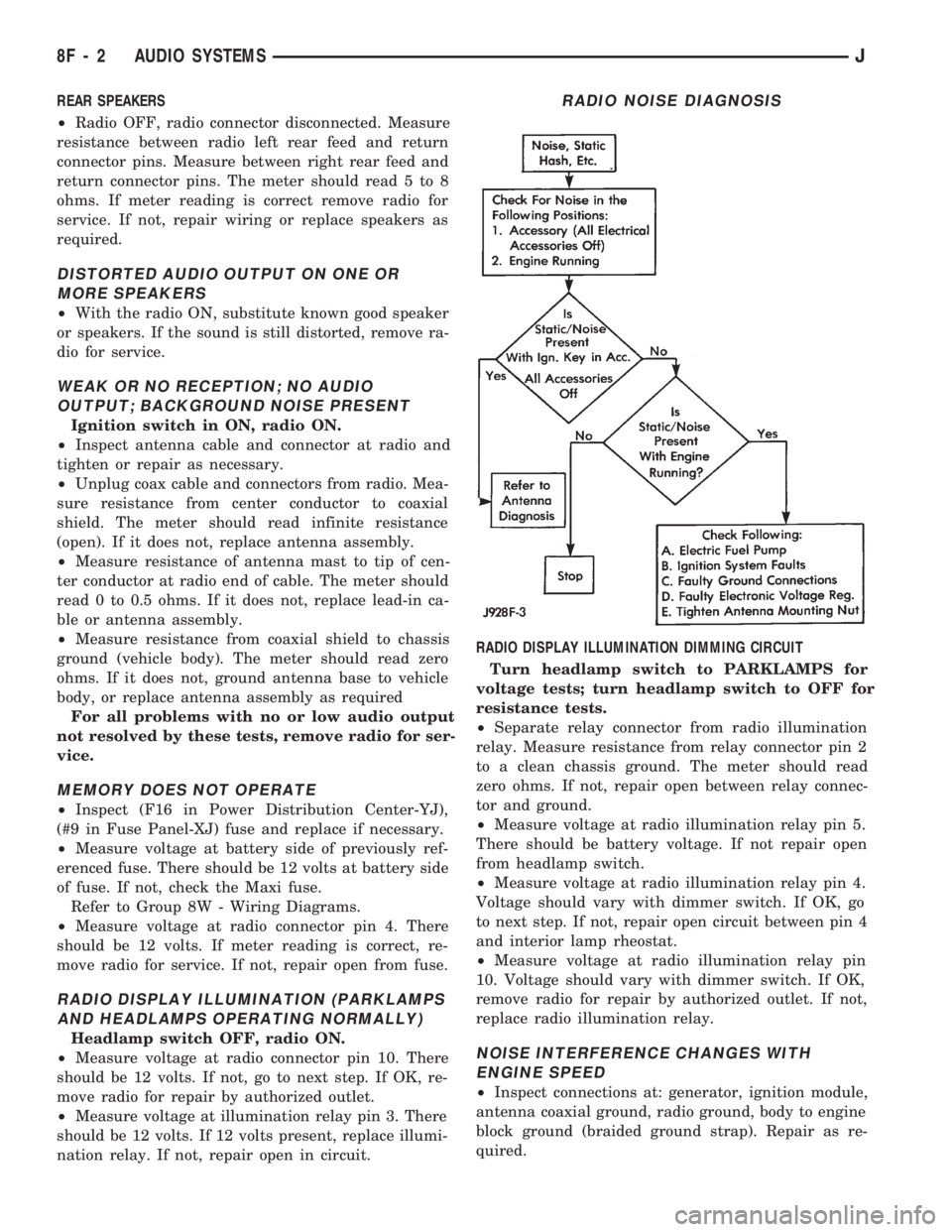
RADIO NOISE DIAGNOSIS
8F - 2 AUDIO SYSTEMSJ
Page 379 of 1784
XJ SERVICE PROCEDURES
RADIO REPLACEMENT
(1) Disconnect negative cable from battery.
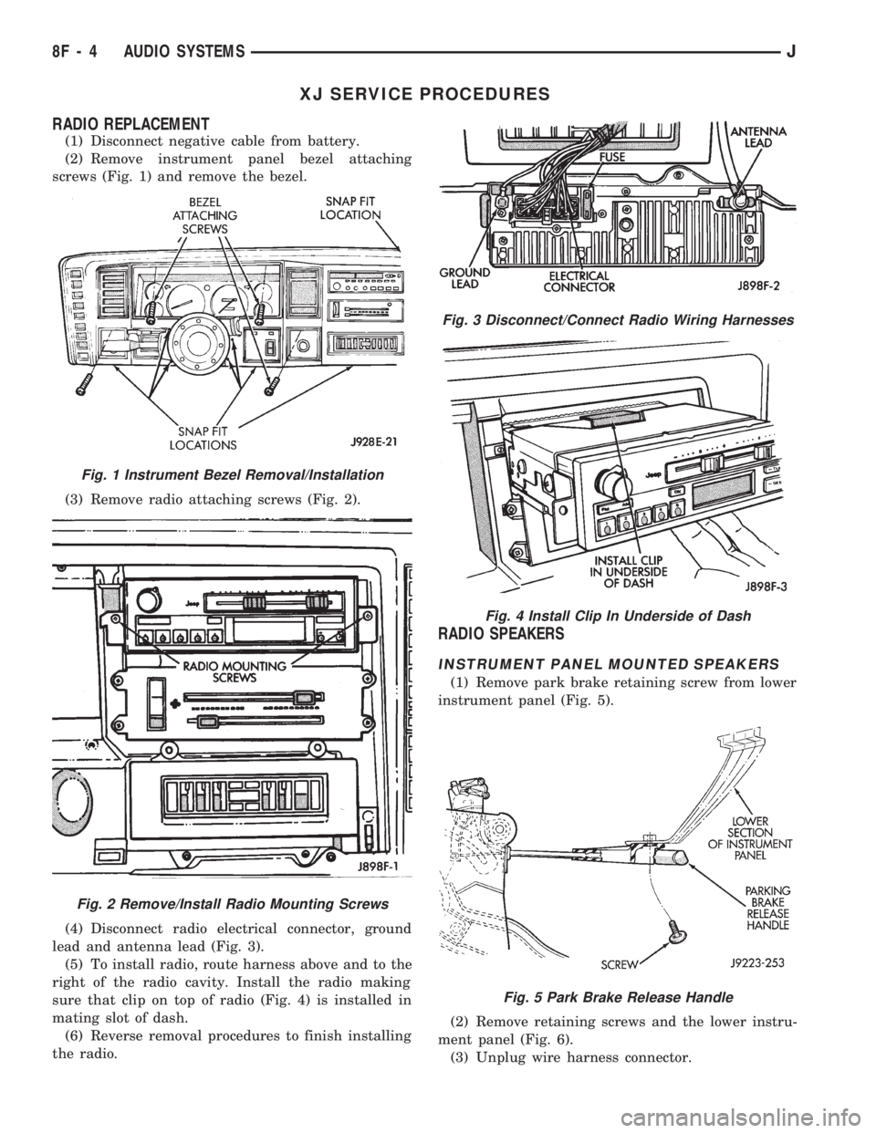
(2) Remove instrument panel bezel attaching
screws (Fig. 1) and remove the bezel.
(3) Remove radio attaching screws (Fig. 2).
(4) Disconnect radio electrical connector, ground
lead and antenna lead (Fig. 3).
(5) To install radio, route harness above and to the
right of the radio cavity. Install the radio making
sure that clip on top of radio (Fig. 4) is installed in
mating slot of dash.
(6) Reverse removal procedures to finish installing
the radio.
RADIO SPEAKERS
INSTRUMENT PANEL MOUNTED SPEAKERS
(1) Remove park brake retaining screw from lower
instrument panel (Fig. 5).
(2) Remove retaining screws and the lower instru-
ment panel (Fig. 6).
(3) Unplug wire harness connector.
Fig. 3 Disconnect/Connect Radio Wiring Harnesses
Fig. 4 Install Clip In Underside of Dash
Fig. 5 Park Brake Release Handle
Fig. 1 Instrument Bezel Removal/Installation
Fig. 2 Remove/Install Radio Mounting Screws
8F - 4 AUDIO SYSTEMSJ
Page 381 of 1784
INSTALLATION
(1) Connect speaker at wiring harness.
(2) Install speaker.
(3) Install trim panel by pushing in the plastic
trees.
(4) Install door panel screws.
YJ SERVICE PROCEDURES
RADIO REPLACEMENT
(1) Disconnect negative cable from battery.
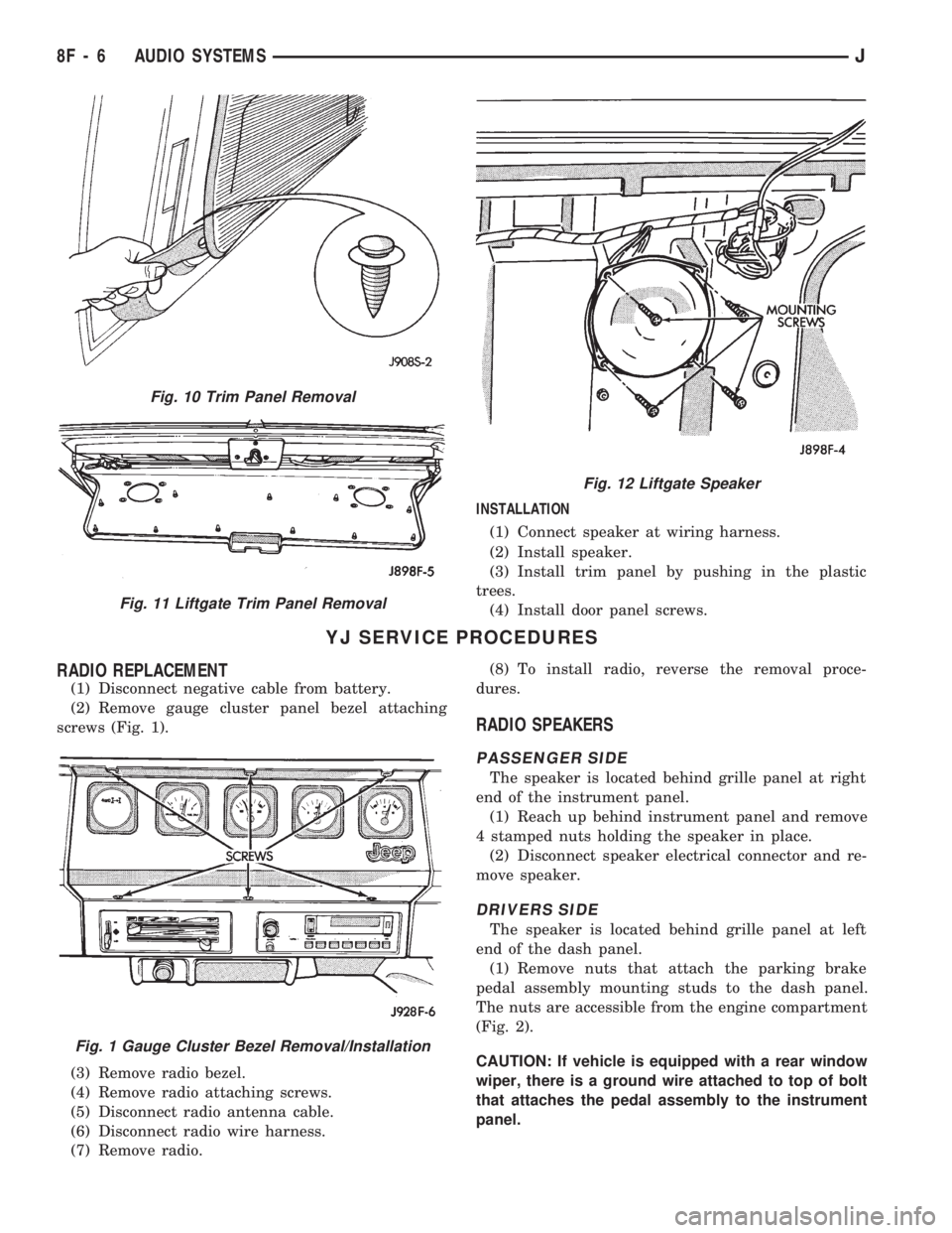
(2) Remove gauge cluster panel bezel attaching
screws (Fig. 1).
(3) Remove radio bezel.
(4) Remove radio attaching screws.
(5) Disconnect radio antenna cable.
(6) Disconnect radio wire harness.
(7) Remove radio.(8) To install radio, reverse the removal proce-
dures.
RADIO SPEAKERS
PASSENGER SIDE
The speaker is located behind grille panel at right
end of the instrument panel.
(1) Reach up behind instrument panel and remove
4 stamped nuts holding the speaker in place.
(2) Disconnect speaker electrical connector and re-
move speaker.
DRIVERS SIDE
The speaker is located behind grille panel at left
end of the dash panel.
(1) Remove nuts that attach the parking brake
pedal assembly mounting studs to the dash panel.
The nuts are accessible from the engine compartment
(Fig. 2).
CAUTION: If vehicle is equipped with a rear window
wiper, there is a ground wire attached to top of bolt
that attaches the pedal assembly to the instrument
panel.
Fig. 10 Trim Panel Removal
Fig. 11 Liftgate Trim Panel Removal
Fig. 12 Liftgate Speaker
Fig. 1 Gauge Cluster Bezel Removal/Installation
8F - 6 AUDIO SYSTEMSJ
Page 383 of 1784
RADIO ANTENNA
INDEX
page page
Antenna Tests............................ 9
General Information........................ 8Replacement............................. 8
GENERAL INFORMATION
AM/FM radio model antennas must have a good
ground to eliminate static. The antenna mast is con-
nected to the inner wire of the coaxial cable and is
not grounded to any part of the vehicle. The coaxial
shield (the wire mesh) surrounding the center con-
ductor wire of the antenna lead-in cable is grounded
to the radio and the antenna base.
REPLACEMENT
XJ
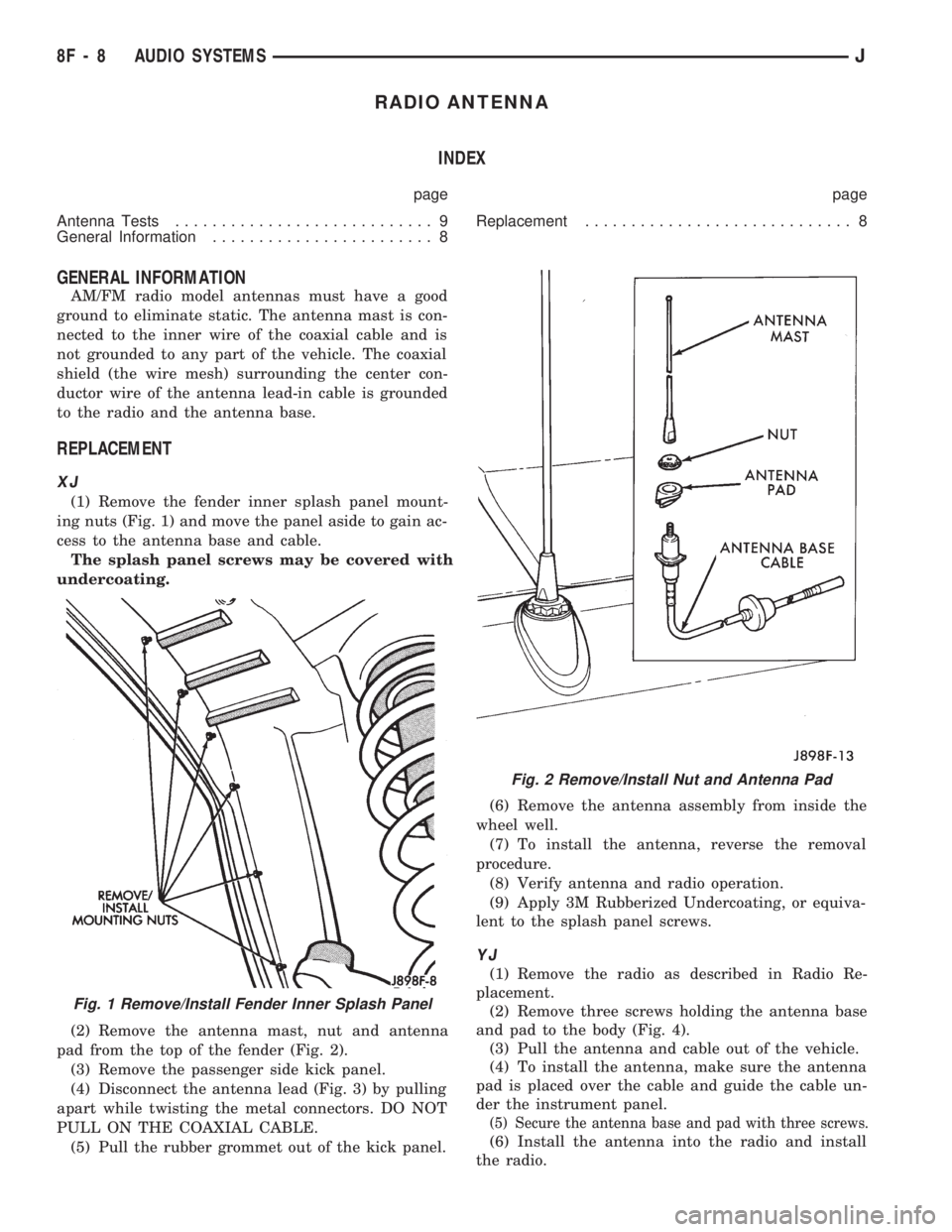
(1) Remove the fender inner splash panel mount-
ing nuts (Fig. 1) and move the panel aside to gain ac-
cess to the antenna base and cable.
The splash panel screws may be covered with
undercoating.
(2) Remove the antenna mast, nut and antenna
pad from the top of the fender (Fig. 2).
(3) Remove the passenger side kick panel.
(4) Disconnect the antenna lead (Fig. 3) by pulling
apart while twisting the metal connectors. DO NOT
PULL ON THE COAXIAL CABLE.
(5) Pull the rubber grommet out of the kick panel.(6) Remove the antenna assembly from inside the
wheel well.
(7) To install the antenna, reverse the removal
procedure.
(8) Verify antenna and radio operation.
(9) Apply 3M Rubberized Undercoating, or equiva-
lent to the splash panel screws.
YJ
(1) Remove the radio as described in Radio Re-
placement.
(2) Remove three screws holding the antenna base
and pad to the body (Fig. 4).
(3) Pull the antenna and cable out of the vehicle.
(4) To install the antenna, make sure the antenna
pad is placed over the cable and guide the cable un-
der the instrument panel.
(5) Secure the antenna base and pad with three screws.
(6) Install the antenna into the radio and install
the radio.
Fig. 1 Remove/Install Fender Inner Splash Panel
Fig. 2 Remove/Install Nut and Antenna Pad
8F - 8 AUDIO SYSTEMSJ
Page 384 of 1784
ANTENNA TESTS
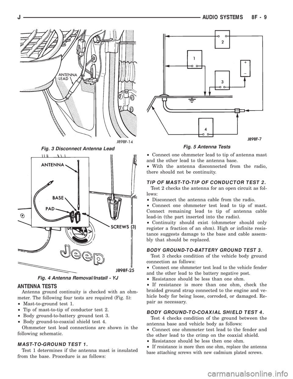
Antenna ground continuity is checked with an ohm-
meter. The following four tests are required (Fig. 5):
²Mast-to-ground test 1.
²Tip of mast-to-tip of conductor test 2.
²Body ground-to-battery ground test 3.
²Body ground-to-coaxial shield test 4.
Ohmmeter test lead connections are shown in the
following schematic.
MAST-TO-GROUND TEST 1.
Test 1 determines if the antenna mast is insulated
from the base. Procedure is as follows:²Connect one ohmmeter lead to tip of antenna mast
and the other lead to the antenna base.
²With the antenna disconnected from the radio,
there should not be continuity.
TIP OF MAST-TO-TIP OF CONDUCTOR TEST 2.
Test 2 checks the antenna for an open circuit as fol-
lows:
²Disconnect the antenna cable from the radio.
²Connect one ohmmeter test lead to tip of mast.
Connect remaining lead to tip of antenna cable
lead-in (the part inserted into the radio).
²Continuity should exist (ohmmeter should only
register a fraction of an ohm). High or infinite resis-
tance suggests damage to the base and cable assem-
bly that should be replaced.
BODY GROUND-TO-BATTERY GROUND TEST 3.
Test 3 checks condition of the vehicle body ground
connection as follows:
²
Connect one ohmmeter test lead to the vehicle fender
and the other lead to the battery negative post.
²Resistance should be less than one ohm.
²If resistance is more than one ohm, check the
braided ground strap connected to the engine and ve-
hicle body for being loose, corroded, or damaged. Re-
pair as necessary.
BODY GROUND-TO-COAXIAL SHIELD TEST 4.
Test 4 checks condition of the ground between the
antenna base and vehicle body as follows:
²Connect one ohmmeter test lead to the fender and
the other lead to the crimp on the coaxial shield.
²Resistance should be less then one ohm.
²
If resistance is more then one ohm, replace the antenna
base attaching screws with new cadmium plated screws.
Fig. 3 Disconnect Antenna Lead
Fig. 4 Antenna Removal/Install - YJ
Fig. 5 Antenna Tests
JAUDIO SYSTEMS 8F - 9
Page 646 of 1784
Wiring Diagram Name Sheet Number
Right Power Mirror.........................73
Power Mirrors.............................73
Power Seat..............................77,78
Left Power Seat Motor Assembly................77
Left Power Seat Switch.......................78
Power Steering Pressure Switch...................15
Powertrain Control Module......11,12,13,14,15,16,17,18,19,
20,21,22,23,35,36,45,55,69
Powertrain Control Module (PCM) Connector..........111
Power Windows.......................79,80,81,82
Left Front Door Window Motor..................81
Left Rear Door Window Motor..................82
Left Rear Door Window Switch..................82
Power Window Switch.......................79
Right Front Door Window Switch................81
Right Front Door Window Motor.................81
Right Rear Door Window Motor.................82
Right Rear Door Window Switch.................82
Power Window Switch.........................79
Printed Circuit Boards.................57,58,59,60,61
Pumps
Front Washer...........................63,64
Rear Washer..............................65
Radiator Fan Motor...........................23
Radio....................................71
Antenna Mast.............................71
Left Front Door Speaker......................71
Left Instrument Panel Speaker..................71
Left Liftgate Speaker.........................72
Right Front Door Speaker.....................72
Right Instrument Panel Speaker.................72
Right Liftgate Speaker........................72
Reading Lamps..............................51
Rear Lighting...................91,92,93,94,95,96,97
Left Back-Up Lamp........................91,93
Left Side Marker Lamp (Rear)................91,93
Left Tail/Stop Lamp.......................91,93
Left Turn Lamp (Amber)....................91,93
Left Turn Relay............................97
License Lamp...........................91,95
Right Back-Up Lamp.......................92,96
Right Side Marker Lamp (Rear)...............92,96
Right Tail/Stop Lamp......................92,96
Right Turn Lamp (Amber)...................92,96
Right Turn Relay...........................97
Stop Lamp Relay...........................97
Trailer Tow Connector........................93
Trailer Tow In-Line Circuit Breaker................97
Rear Lighting With Trailer Tow............93,94,95,96,97
Rear Lighting Without Trailer Tow................91,92
Rear Washer Pump...........................65
Rear Wiper Motor............................65
Rear Wiper/Washer Motor.......................65
Rear Washer Pump...........................65
Rear Wiper Motor............................65
Rear Wiper/Washer Switch......................65
Rear Wiper/Washer Switch Lamp..................47
Reed Switch................................26Wiring Diagram Name Sheet Number
Relays
ABS #1 Relay............................3,31
ABS #2 Relay............................3,31
A/C Compressor Clutch Relay..................3,69
Automatic Shut Down Relay.................3,12,17
Cooling Fan Relay...........................3
EMCC Relay.............................3,27
Engine Starter Relay.......................3,7,8
Fan Control Relay...........................23
Fuel Pump Relay........................3,12,17
Heated Rear Window Relay....................66
High Beam Relay...........................40
Horn Relay...............................34
L.C.D. Illumination Relay......................52
Left Turn Relay............................97
Park Lamp Relay...........................39
Power Door Lock Relay.......................83
Power Door Unlock Relay.....................83
Right Turn Relay...........................97
Stop Lamp Relay...........................97
Relay Center Identification......................113
Remote Keyless Entry System....................28
Remote Keyless Entry Module...................28
Remote Keyless Entry Module Connector...........114
Resistor,Ballast..............................39
Resistor,Blower..............................68
Right Front Door Jamb Switch....................76
Right Front Door Speaker.......................72
Right Front Door Window Switch..................81
Right Front Wheel Sensor.......................29
Right Front Door Connector and Door Lock Switch
Function Chart.............................87
Right Front Door Lock Motor.....................86
Right Instrument Panel Speaker...................72
Right Liftgate Speaker.........................72
Right Front Door Window Connector and Window Lift
Switch Function Chart........................87
Right Rear Door Jamb Switch....................76
Right Rear Door Window Connector and Window Lift
Function Chart.............................88
Right Rear Wheel Sensor.......................29
Right Turn Relay.............................97
Seat Belt Switch.............................74
Seat Belt Warning Indicator Lamp................57,58
Sensors
Ambient Temperature Sensor...................53
Camshaft Position Sensor...................11,20
Crankshaft Position Sensor...................11,20
Engine Coolant Temperature Sensor.............14,19
G Sensor................................30
Heated Oxygen Sensor.....................13,21
Intake Air Temperature Sensor................14,19
Left Front Wheel Sensor......................29
Left Rear Wheel Sensor.......................29
MAP Sensor............................14,19
Pedal Travel Sensor.........................30
Right Front Wheel Sensor.....................29
Right Rear Wheel Sensor......................29
JWIRING DIAGRAMS 8W - 153
Page 766 of 1784
Wiring Diagram Name Sheet Number
Dome/Reading Lamp.........................31
Fog Lamps............................21, 22
Fog Lamp Illumination Lamp...................20
4WD Select Trac Indicator Lamp..............39, 40
Front Headlamps.........................21, 22
Full Time Indicator Lamp...................39, 40
Glove Box Lamp...........................29
Heated Rear Window Lamp....................25
Heater A/C Panel Lamp.......................25
High-Beam Indicator Lamp.....................41
Instrument Cluster Illumination Lamps.............41
Left Backup Lamp..........................55
Left Fog Lamp.............................21
Left Headlamp.............................21
Left Park/Turn Signal Lamp....................21
Left Side Marker...........................55
Left Side Marker Lamp (Front)..................21
Left Tail/Stop Lamp.........................55
Left Turn Indicator Lamp......................41
Left Turn Lamp (Amber)......................55
License Lamp.............................55
Low Washer Indicator Lamp.................39, 40
Maintenance Required Indicator Lamp...........39, 40
Malfunction Indicator Lamp..................39, 40
Park Brake Indicator Lamp.....................40
Park/Turn Signal Lamps....................21, 22
Reading Lamp.............................31
Rear Wiper/Wash Switch Lamp..................26
Right Back-up Lamp.........................56
Right Fog Lamp............................22
Right Headlamp............................22
Right Park/Turn Signal Lamp...................22
Right Side Marker..........................56
Right Side Marker Lamp (Front).................22
Right Tail/Stop Lamp........................56
Right Turn Indicator Lamp.....................41
Right Turn Lamp (Amber).....................56
Seat Belt Indicator Lamp...................39, 40
Side Marker Lamps (Front)..................21, 22
Transfer Case Lamp.........................26
Transmission Range Lamp.....................26
Underhood Lamp...........................28
Upshift Indicator Lamp.....................39, 40
Vanity Lamps.............................31
LCD Illumination Relay.........................57
Left Front Door Jamb Switch.....................50
Left Rear Door Jamb Switch.....................50
Left Speakers............................47, 48
Liftgate Switch..............................50
Low Washer Indicator Lamp...................39, 40
Main Body Connector 1........................70
Maintenance Required Indicator Lamp............39, 40
Map Sensor................................11
Modules
Chime Module.............................43
Fuel Pump Module..........................54
Intermittent Wiper Module.....................33
Powertrain Control Module . .7, 9, 10, 11, 12, 13, 14, 45, 53Wiring Diagram Name Sheet Number
Transmission Control Module.................17, 18
Motors
A/C Heater Blower Motor......................46
Engine Starter Motor.........................6
Front Wiper Motor..........................34
Heater Blower Motor.........................44
Idle Air Control Motor........................14
Radiator Fan Motor..........................7
Rear Wiper Motor..........................36
Oil Pressure and Temperature System...............15
Coolant Temperature Switch....................15
Oil Pressure Switch.........................15
Park Brake Indicator Lamp......................40
Park Brake Switch............................42
Power Distribution Center........................1
Power Distribution Center Application Chart............4
Power Distribution Center Identification...............3
Power Mirror Connector........................61
Power Mirror Switch Assembly...................51
Power Mirrors............................51, 52
Heater Element............................52
Left Power Mirror..........................52
Right Power Mirror.........................52
Powertrain Control Module . . .7, 9, 10, 11, 12, 13, 14, 45, 53
Powertrain Control Module Connector...............73
Pumps
Front Washer.............................34
Rear Washer..............................35
Fuel...................................54
Radiator Fan Motor............................7
Radio.................................47, 48
Antenna Mast.............................47
Left Instrument Panel Speaker..................47
Left Liftgate Speaker.........................48
Radio..................................47
Right Instrument Panel Speaker.................48
Right Liftgate Speaker........................48
Rear Lighting............................55, 56
Left Back-Up Lamp..........................55
Left Side Marker...........................55
Left Tail/Stop Lamp.........................55
Left Turn Lamp (Amber)......................55
License Lamp.............................55
Right Back-Up Lamp.........................56
Right Side Marker..........................56
Right Tail/Stop Lamp........................56
Right Turn Lamp (Amber).....................56
Rear Wiper/Washer.........................35, 36
Rear Washer Pump.........................35
Rear Wiper Motor..........................36
Rear Wiper/Washer Switch.....................35
Reading Lamps..............................31
Relays
A/C Compressor Clutch Relay.................3,45
Automatic Shut Down Relay...................3,9
Engine Starter Relay........................3,6
Fan Control Relay.........................3,7
Fog Lamp Relay...........................21
JWIRING DIAGRAMS 8W - 273