1994 JEEP CHEROKEE cooling
[x] Cancel search: coolingPage 14 of 1784

ENGINE MAINTENANCE
INDEX
page page
Accessory Drive Belt...................... 20
Air-Conditioner Compressor/Hoses/Fittings...... 21
Battery................................ 18
Cooling System.......................... 16
Crankcase Ventilation System............... 17
Engine Air Cleaner Filter Element............ 16
Engine Break-In......................... 13
Engine Oil.............................. 13Engine Oil Change and Filter Replacement..... 15
Engine Oil Filter......................... 14
Engine Supports......................... 20
Exhaust System......................... 20
Fuel Usage StatementÐGas Engines......... 17
Ignition Cables, Distributor Cap and Rotor...... 18
Rubber and Plastic Ducts/Hoses/Tubing....... 19
Spark Plugs............................ 18
ENGINE BREAK-IN
After first starting a new engine, allow it to idle
and warm up for at least 15 seconds before shifting
the transmission into a drive gear.
Drive the vehicle at:
²varying speeds less than 80 km/h (50 mph) for the
first 160 km (100 miles), and
²speeds less than 88 km/h (55 mph) for the first 800
km (500 miles).
Avoid driving at full-throttle for extended periods
of time. Also, avoid fast acceleration and sudden
stops.
A special break-in engine oil is not required. The
original oil installed in a vehicle is a quality lubri-
cant. There is no requirement to have the oil
changed or the oil filter replaced until the first
scheduled maintenance interval.
The engine oil, coolant and all the other engine re-
lated fluid levels should be determined on a regular
basis.
ENGINE OIL
SPECIFICATIONS
API SERVICE GRADE
For maximum engine protection during all driving
conditions, install an engine oil that conforms to API
Service Grade. MOPAR Engine Oil conforms to all of
these API Service Grades.
SAE VISCOSITY
SAE designated multi-viscosity grade engine oil is
to protect engines. This type of engine oil can usually
be installed and remain in the engine until the next
scheduled oil change. Select the engine oil viscosity
according to the lowest ambient air temperature ex-
pected before the next scheduled oil change (Fig.1).
Low viscosity engine oil allows easier engine starting
during cold weather. SAE 5W-30 viscosity engine oil
is recommended when the ambient air temperatures
consistently decrease to below 10ÉF (-12ÉC).ENERGY CONSERVING OIL
In selecting the correct API grade and SAE grade,
anENERGY CONSERVINGtype engine oil is also
recommended.
CONTAINER IDENTIFICATION
Standard engine oil notations have been adopted
for selection of engine oil. The notations are located
on side of plastic bottles and on the top of engine oil
cans (Fig. 2).
²The top, outer field contains theAPI Service
Gradenotation for the engine oil.
Fig. 1 Temperature/Engine Oil Viscosity
Fig. 2 Engine Oil Container Standard Notations
JLUBRICATION AND MAINTENANCE 0 - 13
Page 17 of 1784
CAUTION: Do not overfill the engine crankcase with
oil. This will cause oil aeration and result in a de-
crease in the engine oil pressure.
(9) Start the engine and observe the oil pressure
gauge or warning lamp. If the pressure does not in-
crease or the warning lamp does not go out, stop the
engine and determine the cause of the problem.
USED ENGINE OIL DISPOSAL
Care should be exercised when disposing used en-
gine oil after it has been drained from a vehicle en-
gine. Refer to the WARNING listed above.
COOLING SYSTEM
WARNING: USE EXTREME CAUTION WHEN RE-
MOVING THE RADIATOR CAP IF THE ENGINE IS
OPERATING. DO NOT PUT YOUR HANDS NEAR
THE DRIVE BELT(S), PULLEYS OR FAN BLADE. DO
NOT STAND IN A DIRECT LINE WITH THE FAN
BLADE.
RECOMMENDED MAINTENANCE
The engine coolant level should be determined at
least once a month and more often during periods of
hot weather. Add coolant as necessary.
COOLANT LEVEL
With the engine at normal operating temperature,
observe the coolant level in thecoolant recovery bot-
tle. The coolant level must be at least above the ADD
mark and preferably at the FULL mark. Add coolant
to the coolant recovery bottleonly, if necessary.
REQUIRED MAINTENANCE
Check coolant level, and inspect condition of cool-
ing system hoses and clamps after each 12 000-km
(7,500-miles).
Initially, coolant must be drained and cooling sys-
tem flushed and filled after the first 36 months of op-
eration. Thereafter, after each 24-months interval of
vehicle operation.
RECOMMENDED MAINTENANCE
The engine cooling system should be inspected for
proper operation and for component failure at least
every 12 months.
WARNING: IF THE ENGINE HAS BEEN RECENTLY
OPERATED, USE EXTREME CARE WHEN REMOV-
ING THE RADIATOR CAP TO AVOID SCALDING
WITH HOT, PRESSURIZED COOLANT.
For additional information, refer to Section 7, Cool-
ing System.COOLANT FREEZE PROTECTION
Jeeptcooling systems contain a 50/50 mixture of
anti-freeze and distilled water coolant. This is the
recommended coolant mixture for most ambient tem-
peratures. The factory-installed anti-freeze is formu-
lated to prevent corrosion on all cooling system metal
surfaces.
The degree of coolant freeze protection should be
tested every 12 months. If the coolant is contami-
nated orrustyin appearance, cooling system should
be drained and filled with a 50/50 mixture of fresh
coolant. For additional information, refer to Group
7ÐCooling System.
ENGINE AIR CLEANER FILTER ELEMENT
RECOMMENDED MAINTENANCE
Engine performance and fuel economy can be af-
fected by a restricted air cleaner filter. The filter
should be inspected on a regular basis for excessive
air restriction.
If the filter element is saturated with oil, replace
the filter element.
REQUIRED MAINTENANCE
Engine air cleaner filter must be replaced after
each 48 000-km (30,000-miles).
If a vehicle is frequently operated in dusty
areas, the air cleaner filter should be inspected
often.
FILTER ELEMENT SERVICE/REPLACEMENT
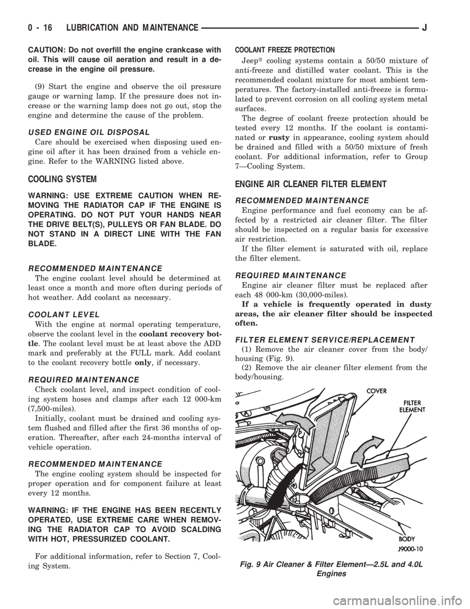
(1) Remove the air cleaner cover from the body/
housing (Fig. 9).
(2) Remove the air cleaner filter element from the
body/housing.
Fig. 9 Air Cleaner & Filter ElementÐ2.5L and 4.0L
Engines
0 - 16 LUBRICATION AND MAINTENANCEJ
Page 21 of 1784
ENGINE SUPPORTS
RECOMMENDED MAINTENANCE
The general condition of the engine supports
should be inspected at the same time as the engine
oil is changed and the oil filter is replaced.
INSPECTION
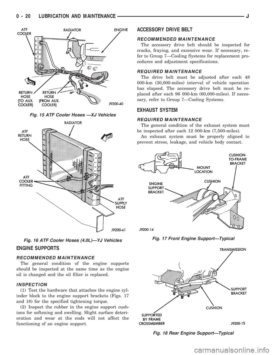
(1) Test the hardware that attaches the engine cyl-
inder block to the engine support brackets (Figs. 17
and 18) for the specified tightening torque.
(2) Inspect the rubber in the engine support cush-
ions for softening and swelling. Slight surface deteri-
oration and wear at the ends will not affect the
functioning of an engine support.
ACCESSORY DRIVE BELT
RECOMMENDED MAINTENANCE
The accessory drive belt should be inspected for
cracks, fraying, and excessive wear. If necessary, re-
fer to Group 7ÐCooling Systems for replacement pro-
cedures and adjustment specifications.
REQUIRED MAINTENANCE
The drive belt must be adjusted after each 48
000-km (30,000-miles) interval of vehicle operation
has elapsed. The accessory drive belt must be re-
placed after each 96 000-km (60,000-miles). If neces-
sary, refer to Group 7ÐCooling Systems.
EXHAUST SYSTEM
REQUIRED MAINTENANCE
The general condition of the exhaust system must
be inspected after each 12 000-km (7,500-miles).
An exhaust system must be properly aligned to
prevent stress, leakage, and vehicle body contact.
Fig. 17 Front Engine SupportÐTypical
Fig. 18 Rear Engine SupportÐTypical
Fig. 15 ATF Cooler Hoses ÐXJ Vehicles
Fig. 16 ATF Cooler Hoses (4.0L)ÐYJ Vehicles
0 - 20 LUBRICATION AND MAINTENANCEJ
Page 111 of 1784
ing the IAC motor pintle in and out of the air control
passage. The IAC motor is positioned when the igni-
tion key is turned to the On position.
A (factory adjusted) set screw is used to mechani-
cally limit the position of the throttle body throttle
plate.Never attempt to adjust the engine idle
speed using this screw.All idle speed functions are
controlled by the PCM.
IGNITION COILÐPCM OUTPUT
System voltage is supplied to the ignition coil pos-
itive terminal. The powertrain control module (PCM)
operates the ignition coil.Base (initial) ignition
timing is not adjustable.The PCM adjusts ignition
timing to meet changing engine operating conditions.
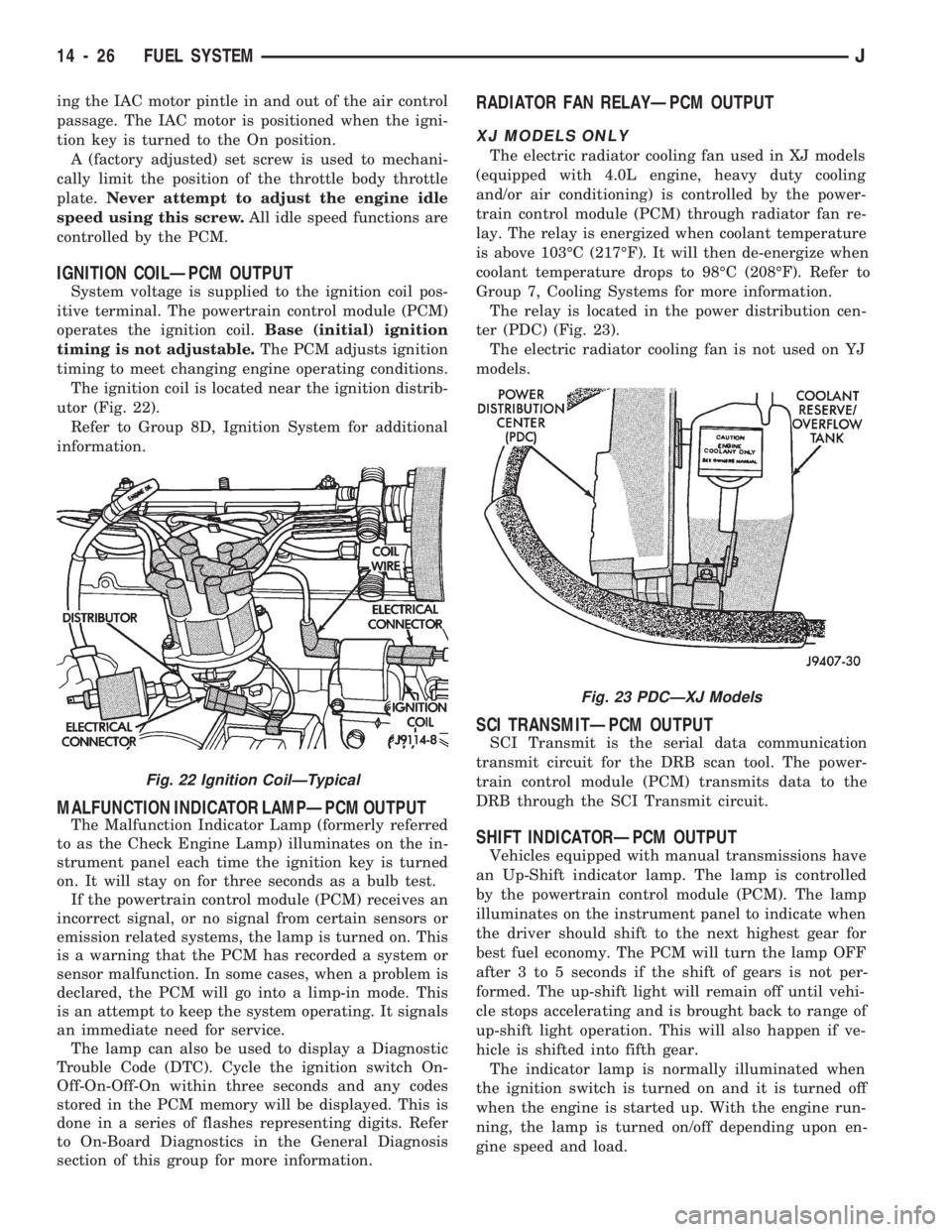
The ignition coil is located near the ignition distrib-
utor (Fig. 22).
Refer to Group 8D, Ignition System for additional
information.
MALFUNCTION INDICATOR LAMPÐPCM OUTPUT
The Malfunction Indicator Lamp (formerly referred
to as the Check Engine Lamp) illuminates on the in-
strument panel each time the ignition key is turned
on. It will stay on for three seconds as a bulb test.
If the powertrain control module (PCM) receives an
incorrect signal, or no signal from certain sensors or
emission related systems, the lamp is turned on. This
is a warning that the PCM has recorded a system or
sensor malfunction. In some cases, when a problem is
declared, the PCM will go into a limp-in mode. This
is an attempt to keep the system operating. It signals
an immediate need for service.
The lamp can also be used to display a Diagnostic
Trouble Code (DTC). Cycle the ignition switch On-
Off-On-Off-On within three seconds and any codes
stored in the PCM memory will be displayed. This is
done in a series of flashes representing digits. Refer
to On-Board Diagnostics in the General Diagnosis
section of this group for more information.
RADIATOR FAN RELAYÐPCM OUTPUT
XJ MODELS ONLY
The electric radiator cooling fan used in XJ models
(equipped with 4.0L engine, heavy duty cooling
and/or air conditioning) is controlled by the power-
train control module (PCM) through radiator fan re-
lay. The relay is energized when coolant temperature
is above 103ÉC (217ÉF). It will then de-energize when
coolant temperature drops to 98ÉC (208ÉF). Refer to
Group 7, Cooling Systems for more information.
The relay is located in the power distribution cen-
ter (PDC) (Fig. 23).
The electric radiator cooling fan is not used on YJ
models.
SCI TRANSMITÐPCM OUTPUT
SCI Transmit is the serial data communication
transmit circuit for the DRB scan tool. The power-
train control module (PCM) transmits data to the
DRB through the SCI Transmit circuit.
SHIFT INDICATORÐPCM OUTPUT
Vehicles equipped with manual transmissions have
an Up-Shift indicator lamp. The lamp is controlled
by the powertrain control module (PCM). The lamp
illuminates on the instrument panel to indicate when
the driver should shift to the next highest gear for
best fuel economy. The PCM will turn the lamp OFF
after 3 to 5 seconds if the shift of gears is not per-
formed. The up-shift light will remain off until vehi-
cle stops accelerating and is brought back to range of
up-shift light operation. This will also happen if ve-
hicle is shifted into fifth gear.
The indicator lamp is normally illuminated when
the ignition switch is turned on and it is turned off
when the engine is started up. With the engine run-
ning, the lamp is turned on/off depending upon en-
gine speed and load.
Fig. 23 PDCÐXJ Models
Fig. 22 Ignition CoilÐTypical
14 - 26 FUEL SYSTEMJ
Page 120 of 1784
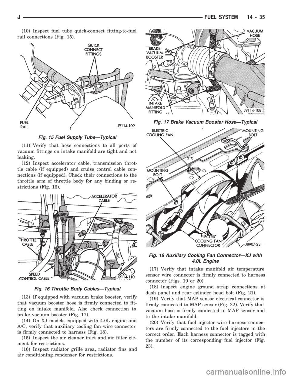
(10) Inspect fuel tube quick-connect fitting-to-fuel
rail connections (Fig. 15).
(11) Verify that hose connections to all ports of
vacuum fittings on intake manifold are tight and not
leaking.
(12) Inspect accelerator cable, transmission throt-
tle cable (if equipped) and cruise control cable con-
nections (if equipped). Check their connections to the
throttle arm of throttle body for any binding or re-
strictions (Fig. 16).
(13) If equipped with vacuum brake booster, verify
that vacuum booster hose is firmly connected to fit-
ting on intake manifold. Also check connection to
brake vacuum booster (Fig. 17).
(14) On XJ models equipped with 4.0L engine and
A/C, verify that auxiliary cooling fan wire connector
is firmly connected to harness (Fig. 18).
(15) Inspect the air cleaner inlet and air filter ele-
ment for restrictions.
(16) Inspect radiator grille area, radiator fins and
air conditioning condenser for restrictions.(17) Verify that intake manifold air temperature
sensor wire connector is firmly connected to harness
connector (Figs. 19 or 20).
(18) Inspect engine ground strap connections at
dash panel and rear cylinder head bolt (Fig. 21).
(19) Verify that MAP sensor electrical connector is
firmly connected to MAP sensor (Fig. 22). Verify that
vacuum hose is firmly connected to MAP sensor and
to the intake manifold.
(20) Verify that fuel injector wire harness connec-
tors are firmly connected to the fuel injectors in the
correct order. Each harness connector is tagged with
the number of its corresponding fuel injector (Fig.
23).
Fig. 15 Fuel Supply TubeÐTypical
Fig. 16 Throttle Body CablesÐTypical
Fig. 17 Brake Vacuum Booster HoseÐTypical
Fig. 18 Auxiliary Cooling Fan ConnectorÐXJ with
4.0L Engine
JFUEL SYSTEM 14 - 35
Page 131 of 1784
IDLE AIR CONTROL MOTOR TEST
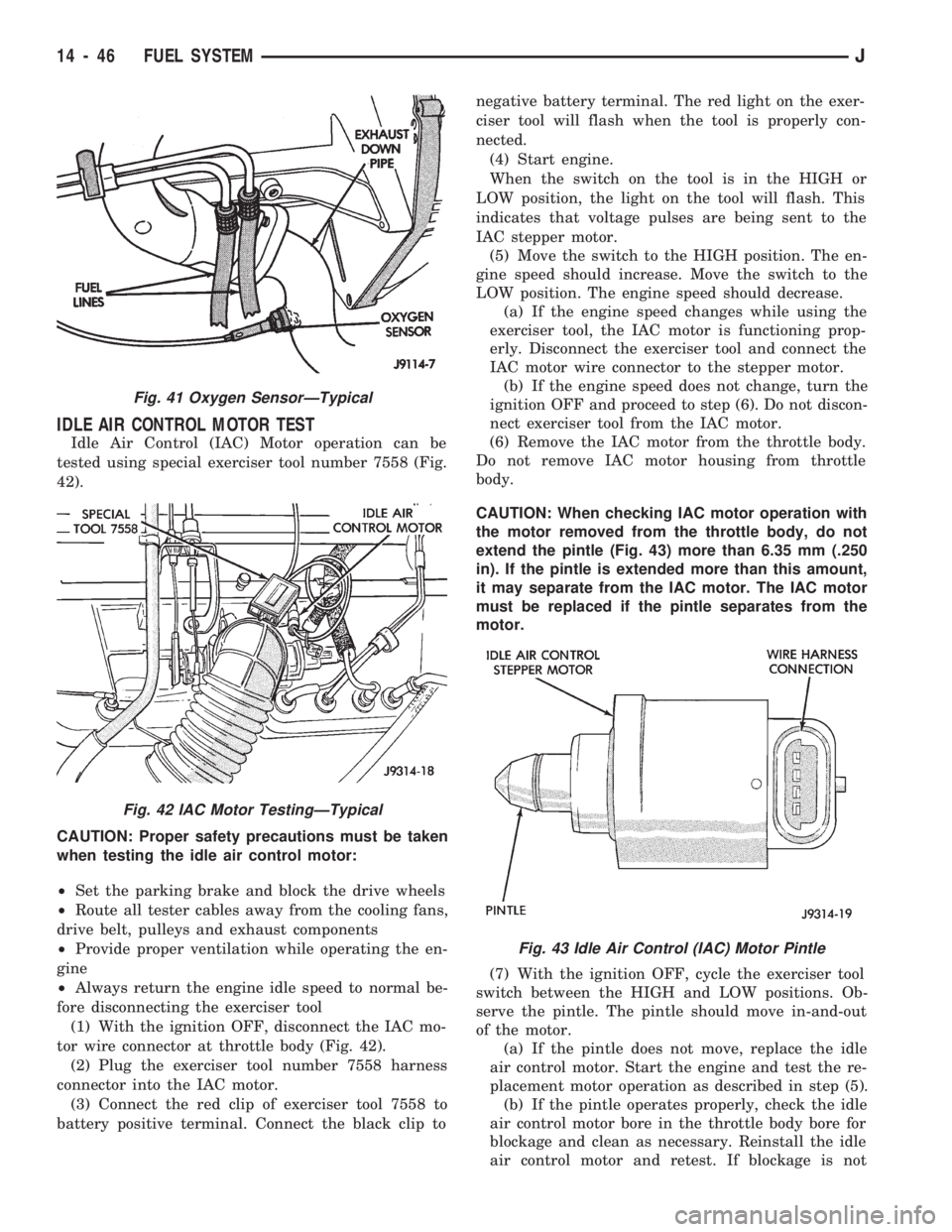
Idle Air Control (IAC) Motor operation can be
tested using special exerciser tool number 7558 (Fig.
42).
CAUTION: Proper safety precautions must be taken
when testing the idle air control motor:
²Set the parking brake and block the drive wheels
²Route all tester cables away from the cooling fans,
drive belt, pulleys and exhaust components
²Provide proper ventilation while operating the en-
gine
²Always return the engine idle speed to normal be-
fore disconnecting the exerciser tool
(1) With the ignition OFF, disconnect the IAC mo-
tor wire connector at throttle body (Fig. 42).
(2) Plug the exerciser tool number 7558 harness
connector into the IAC motor.
(3) Connect the red clip of exerciser tool 7558 to
battery positive terminal. Connect the black clip tonegative battery terminal. The red light on the exer-
ciser tool will flash when the tool is properly con-
nected.
(4) Start engine.
When the switch on the tool is in the HIGH or
LOW position, the light on the tool will flash. This
indicates that voltage pulses are being sent to the
IAC stepper motor.
(5) Move the switch to the HIGH position. The en-
gine speed should increase. Move the switch to the
LOW position. The engine speed should decrease.
(a) If the engine speed changes while using the
exerciser tool, the IAC motor is functioning prop-
erly. Disconnect the exerciser tool and connect the
IAC motor wire connector to the stepper motor.
(b) If the engine speed does not change, turn the
ignition OFF and proceed to step (6). Do not discon-
nect exerciser tool from the IAC motor.
(6) Remove the IAC motor from the throttle body.
Do not remove IAC motor housing from throttle
body.
CAUTION: When checking IAC motor operation with
the motor removed from the throttle body, do not
extend the pintle (Fig. 43) more than 6.35 mm (.250
in). If the pintle is extended more than this amount,
it may separate from the IAC motor. The IAC motor
must be replaced if the pintle separates from the
motor.
(7) With the ignition OFF, cycle the exerciser tool
switch between the HIGH and LOW positions. Ob-
serve the pintle. The pintle should move in-and-out
of the motor.
(a) If the pintle does not move, replace the idle
air control motor. Start the engine and test the re-
placement motor operation as described in step (5).
(b) If the pintle operates properly, check the idle
air control motor bore in the throttle body bore for
blockage and clean as necessary. Reinstall the idle
air control motor and retest. If blockage is not
Fig. 41 Oxygen SensorÐTypical
Fig. 42 IAC Motor TestingÐTypical
Fig. 43 Idle Air Control (IAC) Motor Pintle
14 - 46 FUEL SYSTEMJ
Page 140 of 1784
REMOVAL
(1) Disconnect the electrical connector from the
sensor.
(2) Remove the sensor from the intake manifold.
INSTALLATION
(1) Install the sensor into the intake manifold.
Tighten the sensor to 28 Nzm (20 ft. lbs.) torque.
(2) Connect the electrical connector to the sensor.
CRANKSHAFT POSITION SENSOR
For description, operation and removal/installation
procedures, refer to Group 8D, Ignition Systems in
this manual.
ENGINE COOLANT TEMPERATURE SENSOR
The coolant temperature sensor is installed in the
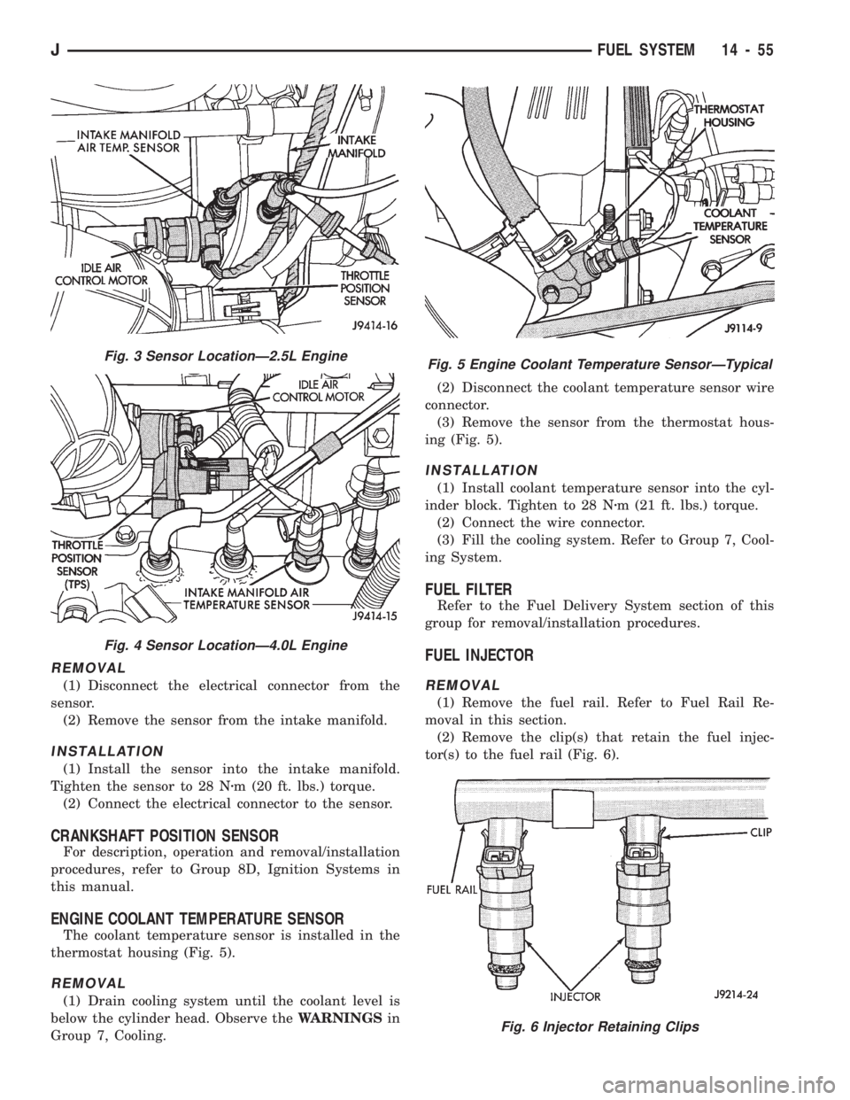
thermostat housing (Fig. 5).
REMOVAL
(1) Drain cooling system until the coolant level is
below the cylinder head. Observe theWARNINGSin
Group 7, Cooling.(2) Disconnect the coolant temperature sensor wire
connector.
(3) Remove the sensor from the thermostat hous-
ing (Fig. 5).
INSTALLATION
(1) Install coolant temperature sensor into the cyl-
inder block. Tighten to 28 Nzm (21 ft. lbs.) torque.
(2) Connect the wire connector.
(3) Fill the cooling system. Refer to Group 7, Cool-
ing System.
FUEL FILTER
Refer to the Fuel Delivery System section of this
group for removal/installation procedures.
FUEL INJECTOR
REMOVAL
(1) Remove the fuel rail. Refer to Fuel Rail Re-
moval in this section.
(2) Remove the clip(s) that retain the fuel injec-
tor(s) to the fuel rail (Fig. 6).
Fig. 3 Sensor LocationÐ2.5L Engine
Fig. 4 Sensor LocationÐ4.0L Engine
Fig. 5 Engine Coolant Temperature SensorÐTypical
Fig. 6 Injector Retaining Clips
JFUEL SYSTEM 14 - 55
Page 231 of 1784
Check flywheel runout if misalignment is sus-
pected. Runout should not exceed 0.08 mm (0.003
in.). Measure runout at the outer edge of the fly-
wheel face with a dial indicator. Mount the dial indi-
cator on a stud installed in place of one of the
flywheel attaching bolts.
Clean the crankshaft flange before mounting the
flywheel. Dirt and grease on the flange surface may
cock the flywheel causing excessive runout.
Check condition of the flywheel hub and attaching
bolts. Replace the flywheel if the hub exhibits cracks
in the area of the attaching bolt holes.
Install new attaching bolts whenever the flywheel
is replaced and use Mopar Lock N' Seal, or Loctite
242 on the replacement bolt threads.
Recommended flywheel bolt torques are:
²142 Nzm (105 ft. lbs.) for 6-cylinder flywheels
²68 Nzm (50 ft. lbs.) plus an additional turn of 60É
for 4-cylinder flywheels
Inspect the teeth on the starter ring gear.If the
teeth are worn or damaged, the flywheel should
be replaced as an assembly. This is the recom-
mended and preferred method of repair.
In cases where a new flywheel is not readily avail-
able, a replacement ring gear can be installed. How-
ever, the following precautions must be observed to
avoid damaging the flywheel and replacement gear.
(a) Mark position of the old gear for alignment
reference on the flywheel. Use a scriber for this
purpose.
(b) Wear protective goggles or approved safety
glasses. Also wear heat resistent gloves when han-
dling a heated ring gear.
(c) Remove the old gear by cutting most of the
way through it (at one point) with an abrasive cut-
off wheel. Then complete removal with a cold chisel
or punch.(d) The ring gear is a shrink fit on the flywheel.
This means the gear must be expanded by heating
in order to install it.The method of heating and
expanding the gear is extremely important.
Every surface of the gear must be heated at the
same time to produce uniform expansion. An oven
or similar enclosed heating device must be used.
Temperature required for uniform expansion is ap-
proximately 375É F.
CAUTION: Do not use an oxy/acetylene torch to re-
move the old gear, or to heat and expand a new
gear. The high temperature of the torch flame can
cause localized heating that will damage the fly-
wheel. In addition, using the torch to heat a replace-
ment gear will cause uneven heating and
expansion. The torch flame can also anneal the
gear teeth resulting in rapid wear and damage after
installation.
(e) The heated gear must be installed evenly to
avoid misalignment or distortion. A shop press and
suitable press plates should be used to install the
gear if at all possible.
(f) Be sure to wear eye and hand protection.
Heat resistent gloves and safety goggles are needed
for personal safety. Also use metal tongs, vise grips,
or similar tools to position the gear as necessary
for installation.
(g) Allow the flywheel and ring gear to cool down
before installation. Set the assembly on a work-
bench and let it cool in normal shop air.
CAUTION: Do not use water, or compressed air to
cool the flywheel. The rapid cooling produced by
water or compressed air can distort, or crack the
gear and flywheel.
6 - 16 CLUTCH SERVICEJ