1994 JEEP CHEROKEE four wheel drive
[x] Cancel search: four wheel drivePage 10 of 1784
²if the vehicle is damaged, secure the loose and pro-
truding parts;
²always use a safety chain system that is indepen-
dent of the lifting and towing equipment;
²do not allow any of the towing equipment to con-
tact the disabled vehicle's fuel tank;
²do not allow anyone to be under the disabled vehi-
cle while it is lifted by the towing equipment;
²do not allow passengers to ride in a vehicle being
towed;
²always observe all state and local laws involving
warning signals, night illumination, speed, etc.
²do not attempt a towing operation that could jeop-
ardize the safety of the operator, bystanders or other
motorists;
²do not exceed a towing speed of 48 km/h (30 mph);
²avoid towing distances of more than 24 km (15
miles) whenever possible; and
²do not attach tow chains or a tow sling to a
bumper, the steering linkage, the universal joints,
the constant velocity (CV) joints, or a drive shaft.
CLEARANCES AND RAMP ANGLE
SURFACE CLEARANCE
The end of the disabled vehicle that is attached to
the tow vehicle should be lifted a minimum of 10 cm
or four inches off the surface. Inspect to ensure that
the opposite end of the disabled vehicle has clearance
from the surface.
RAMP ANGLEÐFLAT-BED TOWING
If a vehicle with flat-bed towing equipment is used,
the approach ramp angle should not exceed 15 de-
grees.
SLING-TYPE, FRONT-END TOWING
XJ VEHICLES
Use the following guidelines when the tow vehicle
is attached to the front end of a disabled vehicle.
(1) Always tow with the front wheels lifted off the
surface and turned all the way to the right.
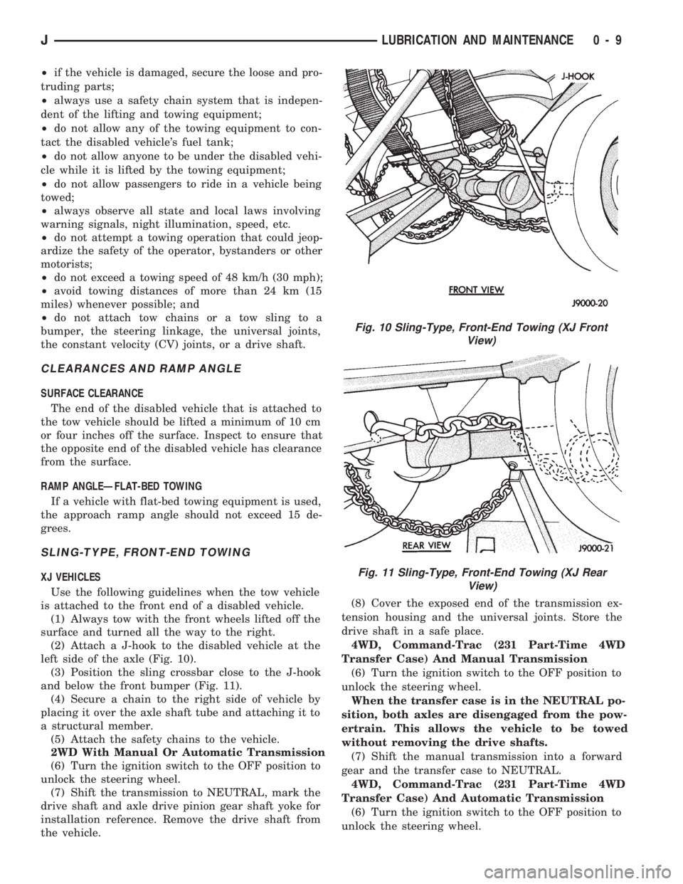
(2) Attach a J-hook to the disabled vehicle at the
left side of the axle (Fig. 10).
(3) Position the sling crossbar close to the J-hook
and below the front bumper (Fig. 11).
(4) Secure a chain to the right side of vehicle by
placing it over the axle shaft tube and attaching it to
a structural member.
(5) Attach the safety chains to the vehicle.
2WD With Manual Or Automatic Transmission
(6) Turn the ignition switch to the OFF position to
unlock the steering wheel.
(7) Shift the transmission to NEUTRAL, mark the
drive shaft and axle drive pinion gear shaft yoke for
installation reference. Remove the drive shaft from
the vehicle.(8) Cover the exposed end of the transmission ex-
tension housing and the universal joints. Store the
drive shaft in a safe place.
4WD, Command-Trac (231 Part-Time 4WD
Transfer Case) And Manual Transmission
(6) Turn the ignition switch to the OFF position to
unlock the steering wheel.
When the transfer case is in the NEUTRAL po-
sition, both axles are disengaged from the pow-
ertrain. This allows the vehicle to be towed
without removing the drive shafts.
(7) Shift the manual transmission into a forward
gear and the transfer case to NEUTRAL.
4WD, Command-Trac (231 Part-Time 4WD
Transfer Case) And Automatic Transmission
(6) Turn the ignition switch to the OFF position to
unlock the steering wheel.
Fig. 10 Sling-Type, Front-End Towing (XJ Front
View)
Fig. 11 Sling-Type, Front-End Towing (XJ Rear
View)
JLUBRICATION AND MAINTENANCE 0 - 9
Page 13 of 1784
When the transfer case is in the NEUTRAL po-
sition, both axles are disengaged from the pow-
ertrain. This allows the vehicle to be towed
without removing the drive shafts.
(2) Shift the transfer case to NEUTRAL.
(3) The vehicle can now be towed with the front
wheels raised (refer to Sling-Type, Front-End Tow-
ing).
VEHICLE DOORS LOCKED
Place a tow dolly under the rear wheels (Fig. 14)
and tow with the front end raised (refer to Sling-
Type, Front-End Towing).
4WD EMERGENCY TOWINGÐTRANSFER CASE
NOT SHIFTED TO NEUTRAL
When a situation arises and the transfer case can-
not be shifted to NEUTRAL, any of the following
methods can be used to tow a 4WD vehicle.
Drive shafts not removed, place the rear
wheels on a tow dolly and tow with the front
end raised.
Drive shafts not removed, place the front
wheels on a tow dolly and tow with the rear end
raised.
Rear drive shaft removed, tow with the front
end raised.
Front drive shaft removed, tow with the rear
end raised.
Both drive shafts removed, tow with all four
wheels on the road surface.
(1) Turn ignition key switch to the unlocked (OFF)
position.
(2) Shift the transmission to the NEUTRAL posi-
tion.
(3) Determine the method by which the vehicle
will be towed and prepare the vehicle for towing.
(4) Connect the vehicle to the tow vehicle. Refer to
the applicable procedure.
FLAT TOWING (4 TIRES/WHEELS ON
SURFACE)
Tow a vehicle in this manner only when all four
wheels will freely rotate. Prepare the vehicle accord-
ing to the following procedures.
2WD VEHICLES
(1) Mark the drive shaft and the axle drive pinion
gear shaft yoke for installation alignment reference.
(2) Remove the drive shaft. Install a protective
covering over the drive shaft U-joints to retain them
assembled and protected.
(3) Cover the open end of the transmission exten-
sion housing.4WD VEHICLES
(1) Mark the drive shafts and the axle drive pinion
gear shaft yokes for installation alignment reference.
(2) Remove the drive shafts. Install a protective
covering over the drive shaft U-joints/CV-joints to re-
tain them assembled and protected.
(3) Cover the exposed ends of the transfer case.
CAUTION: Whenever a drive shaft has been re-
moved and installed, check the transmission fluid
level of the transmission and transfer case. Driving
a vehicle with low tranfer case fluid can damage the
transmission and transfer case.
EMERGENCY TOW HOOKS
WARNING: REMAIN AT A SAFE DISTANCE FROM A
VEHICLE THAT IS BEING TOWED VIA ITS TOW
HOOKS. THE TOW STRAPS/CHAINS COULD POSSI-
BLY BREAK AND CAUSE SERIOUS INJURY.
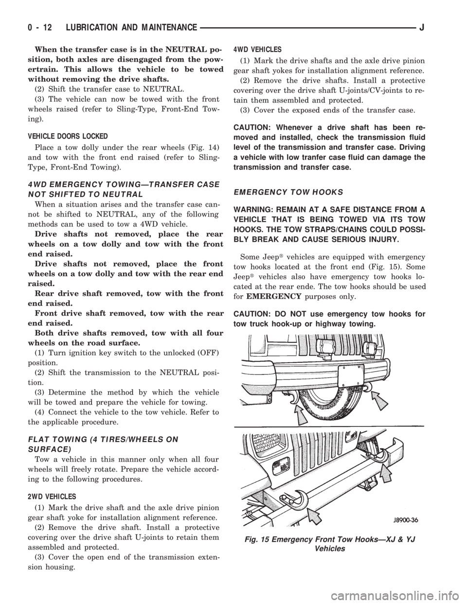
Some Jeeptvehicles are equipped with emergency
tow hooks located at the front end (Fig. 15). Some
Jeeptvehicles also have emergency tow hooks lo-
cated at the rear ende. The tow hooks should be used
forEMERGENCYpurposes only.
CAUTION: DO NOT use emergency tow hooks for
tow truck hook-up or highway towing.
Fig. 15 Emergency Front Tow HooksÐXJ & YJ
Vehicles
0 - 12 LUBRICATION AND MAINTENANCEJ
Page 39 of 1784
axle assembly to the frame. The lower arms uses
shims at the frame mount to allow for adjustment of
caster and pinion angle. The suspension arm travel
(jounce or rebound) is limited through the use of rub-
ber bumpers.
Suspension components which use rubber bushings
should be tightened at vehicle ride height. This will
prevent premature failure of the bushing and main-
tain ride comfort. Bushings must never be lubricated.
The coil springs control ride quality and maintain
proper ride height. The coil springs mount up in the
fender shield which is part of the unitized body
bracket. A rubber isolator is located between the top
of the spring and the frame. The bottom of the spring
seats on a axle pad and is retained with a clip.
The shock absorbers dampen jounce and rebound of
the vehicle over various road conditions. The top of
the shock absorbers are bolted to the frame. The bot-
tom of the shocks are bolted to the axle spring
bracket.
The stabilizer bar is used to minimize vehicle front
sway during turns. The spring steel bar helps to con-
trol the vehicle body in relationship to the suspen-
sion. The bar extends across the front underside of
the chassis and connects to the frame rails. Links are
connected from the bar to the axle brackets. Stabi-
lizer bar mounts are isolated by rubber bushings.
The track bar is used to minimize front axle side-
to-side movement. The bar is attached to a frame rail
bracket with a ball stud and isolated with a bushing
at the axle bracket.
TUBE AXLE (2WD VEHICLES)
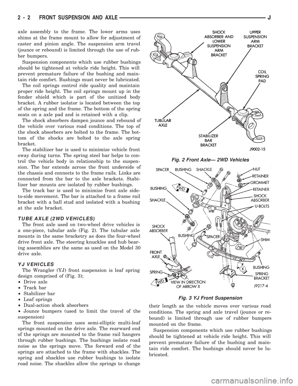
The front axle used on two-wheel drive vehicles is
a one-piece, tubular axle (Fig. 2). The tubular axle
mounts in the same bracketry as does the four-wheel
drive front axle. The steering knuckles and hub bear-
ing assemblies are the same as used on the Model 30
drive axle.
YJ VEHICLES
The Wrangler (YJ) front suspension is leaf spring
design comprised of (Fig. 3);
²Drive axle
²Track bar
²Stabilizer bar
²Leaf springs
²Dual-action shock absorbers
²Jounce bumpers (used to limit the travel of the
suspension)
The front suspension uses semi-elliptic multi-leaf
springs mounted on the drive axle. The rearward end
of the springs are mounted to the frame rail hangers
through rubber bushings. The bushings isolate road
noise as the springs move. The forward end of the
springs are attached to the frame with shackles. The
spring and shackles use rubber bushings to isolate
road noise. The shackles allow the springs to changetheir length as the vehicle moves over various road
conditions. The spring and axle travel (jounce or re-
bound) is limited through use of rubber bumpers
mounted on the frame.
Suspension components which use rubber bushings
should be tightened at vehicle ride height. This will
prevent premature failure of the bushing and main-
tain ride comfort. The bushings should never be lu-
bricated.
Fig. 2 Front AxleÐ 2WD Vehicles
Fig. 3 YJ Front Suspension
2 - 2 FRONT SUSPENSION AND AXLEJ
Page 57 of 1784
MODEL 30 AXLE AND TUBE AXLE (2WD)
INDEX
page page
Axle Bushing Replacement................. 32
Axle Shaft Ð Cardan U-Joint................ 25
Axle Specifications....................... 46
Backlash and Contact Pattern Analysis........ 44
Cleaning/Inspection....................... 35
Differential and Pinion Measurement.......... 38
Differential Assembly...................... 36
Differential Disassembly.................... 34
Differential Installation..................... 43
Differential Removal...................... 32
Differential Shim Pack Measurement and Adjustment.42
Drive Axle Assembly ReplacementÐXJ Vehicles . 21
Drive Axle Assembly ReplacementÐYJ Vehicles . 21Final Assembly.......................... 44
Hub Bearing and Axle Shaft................ 24
Information............................. 20
Inner Axle Shaft Oil Seal Replacement........ 33
Lubricant Change........................ 22
Lubricant Specifications.................... 20
Pinion Gear Assembly/Installation............ 40
Pinion Gear Depth Information.............. 37
Pinion Removal/Disassembly................ 34
Pinion Seal Replacement.................. 23
Steering Knuckle and Ball Studs............. 30
Vacuum Disconnect Axle Ð YJ Vehicles....... 26
INFORMATION
The housing for Model 30 front axles consists of an
iron center casting (differential housing) with axle
shaft tubes extending from either side. The tubes are
pressed into and welded to the differential housing to
form a one-piece axle housing.
The integral type housing, hypoid gear design has
the centerline of the pinion set above the centerline
of the ring gear.
The axle has a fitting for a vent hose used to re-
lieve internal pressure caused by lubricant vaporiza-
tion and internal expansion.
The axles are equipped with semi-floating axle
shafts, meaning that loads are supported by the hub
bearings. The axle shafts are retained by nuts at the
hub bearings. The hub bearings are bolted to the
steering knuckle at the outboard end of the axle tube
yoke. The hub bearings are serviced as an assembly.
The axles are equipped with ABS brake sensors.
The sensors are attached to the knuckle assemblies
and tone rings are pressed on the axle shaft.Use
care when removing axle shafts as NOT to dam-
age the tone wheel or the sensor.
The stamped steel cover provides a means for in-
spection and servicing the differential.
The Model 30 axle has the assembly part number
and gear ratio listed on a tag. The tag is attached to
the housing cover. Build date identification codes are
stamped on the axle shaft tube cover side.
The differential case is a one-piece design. The dif-
ferential pinion mate shaft is retained with a roll
pin. Differential bearing preload and ring gear back-
lash is adjusted by the use of shims (select thick-
ness). The shims are located between the differential
bearing cones and case. Pinion bearing preload is set
and maintained by the use of collapsible spacer.
PINION GEAR DEPTH MEASUREMENT WITH
PINION GAUGE SET 6774, Pinion Block 6733 and
Dial Indicator C-3339 is performed when;²Axle/differential housing is being replaced
²Original pinion depth shim pack is lost or mis-
placed
²Replacing the differential case
²Original differential bearing shim pack is lost or
misplaced
COMMAND-TRACÐYJ VEHICLES
The Command-Trac system is a vacuum disconnect
axle. The system has a two-piece axle shaft coupled
together by a shift collar. For two-wheel drive oper-
ation, the vacuum motor and shift fork disengages
the axle shaft splines. For four-wheel drive opera-
tion, the vacuum motor and shift fork engages the
splines.
SELEC-TRACÐXJ VEHICLES
The Selec-Trac system is a non-disconnect axle.
Shifting from two-wheel to four-wheel drive is at the
transfer case.
For XJ vehicles equipped withSelec-Tracand
ABS brake system, refer to Group 5ÐBrakes for ad-
ditional service information.
LUBRICANT SPECIFICATIONS
Multi-purpose, hypoid gear lubricant should be
used for Model 30 axles. The lubricant should have
MIL-L-2105C and API GL 5 quality specifications.
MOPARtHypoid Gear Lubricant conforms to both of
these specifications.
²The factory fill for the Model 30 axle is SAE 75W
gear lubricant.Do not use heavier weight lubri-
cant, this will cause axle engagement difficulties.
²The factory installed lubricant quantity for the
NON-DISCONNECT TYPE AXLE is 5061 fluid oz..
²The factory installed lubricant quantity for the
VACUUM-DISCONNECT TYPE AXLE is 5661 fluid
oz..
2 - 20 FRONT SUSPENSION AND AXLEJ
Page 178 of 1784
(3) Install new spring nuts on wheel studs.
(4) Install wheel and lower vehicle.
DISC BRAKE ROTOR THICKNESS
Rotor minimum usable thickness is 22.7 mm (0.89
in.). This dimension is either cast, or stamped on the
rotor hub, or outer edge.
Measure rotor thickness at the center of the brake-
shoe contact surface.
Replace the rotor if worn below minimum thick-
ness. Also replace the rotor if refinishing would re-
duce thickness below the allowable minimum.
DISC BRAKE ROTOR RUNOUT
Check rotor lateral runout whenever pedal pulsa-
tion, or rapid, uneven brakelining wear has occurred.
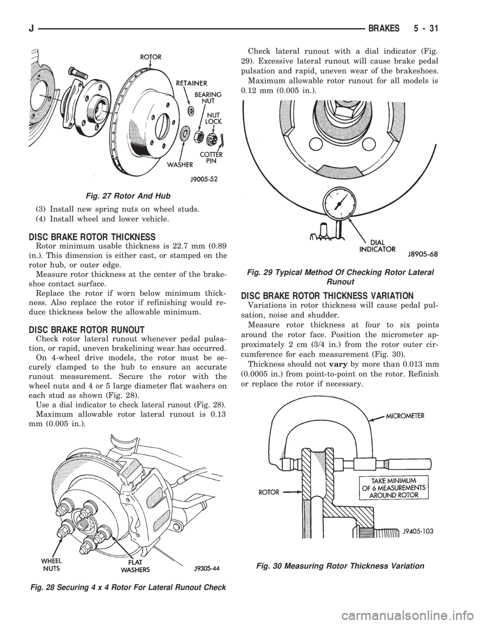
On 4-wheel drive models, the rotor must be se-
curely clamped to the hub to ensure an accurate
runout measurement. Secure the rotor with the
wheel nuts and 4 or 5 large diameter flat washers on
each stud as shown (Fig. 28).
Use a dial indicator to check lateral runout (Fig. 28).
Maximum allowable rotor lateral runout is 0.13
mm (0.005 in.).Check lateral runout with a dial indicator (Fig.
29). Excessive lateral runout will cause brake pedal
pulsation and rapid, uneven wear of the brakeshoes.
Maximum allowable rotor runout for all models is
0.12 mm (0.005 in.).
DISC BRAKE ROTOR THICKNESS VARIATION
Variations in rotor thickness will cause pedal pul-
sation, noise and shudder.
Measure rotor thickness at four to six points
around the rotor face. Position the micrometer ap-
proximately 2 cm (3/4 in.) from the rotor outer cir-
cumference for each measurement (Fig. 30).
Thickness should notvaryby more than 0.013 mm
(0.0005 in.) from point-to-point on the rotor. Refinish
or replace the rotor if necessary.
Fig. 27 Rotor And Hub
Fig. 28 Securing4x4Rotor For Lateral Runout Check
Fig. 29 Typical Method Of Checking Rotor Lateral
Runout
Fig. 30 Measuring Rotor Thickness Variation
JBRAKES 5 - 31
Page 316 of 1784
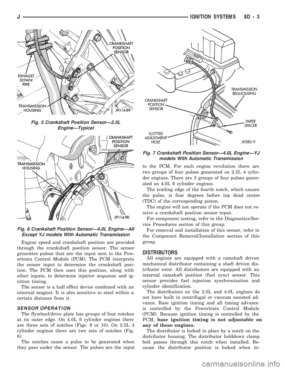
Engine speed and crankshaft position are provided
through the crankshaft position sensor. The sensor
generates pulses that are the input sent to the Pow-
ertrain Control Module (PCM). The PCM interprets
the sensor input to determine the crankshaft posi-
tion. The PCM then uses this position, along with
other inputs, to determine injector sequence and ig-
nition timing.
The sensor is a hall effect device combined with an
internal magnet. It is also sensitive to steel within a
certain distance from it.
SENSOR OPERATION
The flywheel/drive plate has groups of four notches
at its outer edge. On 4.0L 6 cylinder engines there
are three sets of notches (Figs. 9 or 10). On 2.5L 4
cylinder engines there are two sets of notches (Fig.
8).
The notches cause a pulse to be generated when
they pass under the sensor. The pulses are the inputto the PCM. For each engine revolution there are
two groups of four pulses generated on 2.5L 4 cylin-
der engines. There are 3 groups of four pulses gener-
ated on 4.0L 6 cylinder engines.
The trailing edge of the fourth notch, which causes
the pulse, is four degrees before top dead center
(TDC) of the corresponding piston.
The engine will not operate if the PCM does not re-
ceive a crankshaft position sensor input.
For component testing, refer to the Diagnostics/Ser-
vice Procedures section of this group.
For removal and installation of this sensor, refer to
the Component Removal/Installation section of this
group.
DISTRIBUTORS
All engines are equipped with a camshaft driven
mechanical distributor containing a shaft driven dis-
tributor rotor. All distributors are equipped with an
internal camshaft position (fuel sync) sensor. This
sensor provides fuel injection synchronization and
cylinder identification.
The distributors on the 2.5L and 4.0L engines do
not have built in centrifugal or vacuum assisted ad-
vance. Base ignition timing and all timing advance
is controlled by the Powertrain Control Module
(PCM). Because ignition timing is controlled by the
PCM,base ignition timing is not adjustable on
any of these engines.
The distributor is locked in place by a notch on the
distributor housing. The distributor holddown clamp
bolt passes through this notch when installed. Be-
cause the distributor position is locked when in-
Fig. 5 Crankshaft Position SensorÐ2.5L
EngineÐTypical
Fig. 6 Crankshaft Position SensorÐ4.0L EngineÐAll
Except YJ models With Automatic Transmission
Fig. 7 Crankshaft Position SensorÐ4.0L EngineÐYJ
models With Automatic Transmission
JIGNITION SYSTEMS 8D - 3
Page 349 of 1784
other side. When coolant temperature is too high the
switch closes providing a path to ground, and the indi-
cator bulb lights.
TACHOMETER
The tachometer displays the engine speed (RPM).
With the engine running, the tachometer receives an
engine speed signal from the Powertrain Control
Module pin 43 (values shown in Specifications chart).
SPEEDOMETER/ODOMETER SYSTEM
The speedometer/odometer system consists of an elec-
tric speedometer and pushbutton reset odometer
mounted in the cluster. The system also includes the
wire harness from the cluster to the vehicle speed sen-
sor at the transmission, and the adapter and pinion in
the transmission. A signal is sent from a transmission
mounted vehicle speed sensor to the speedometer/odom-
eter circuitry through the wiring harness. Refer to
Group 21 - Transmission for selecting the proper pinion,
and selecting and indexing the proper adapter.
FUEL GAUGE
The fuel gauge pointer position is controlled by a
magnetic field created by electrical current flow through
the coils within the gauge. A change in current flow will
change the magnetic field which changes the pointer po-
sition. The fuel level sender is a variable resistor that
changes electrical resistance with a change of the level
of fuel in the tank (values shown in Specifications
chart).
LOW FUEL WARNING LAMP
The low fuel warning lamp will light when the fuel
level falls below approximately 4 gallons. A low fuel
warning module controls when the lamp will light.
When the module senses 66.5 ohms or less from the
fuel level sender for 10 continuous seconds, the lamp
will light. The lamp will remain on until the module
senses 63.5 ohms or more from the fuel level sender
for 20 continuous seconds.
UPSHIFT INDICATOR LAMP
Vehicles equipped with manual transmissions have an
optional upshift indicator lamp. The lamp is controlled
by the Powertrain Control Module. The lamp lights to
indicate when the driver should shift to the next high-
est gear for best fuel economy. The Powertrain Control
Module will turn the lamp off after 3 to 5 seconds if the
upshift is not performed. The lamp will remain off until
the vehicle stops accelerating and is brought back to the
range of lamp operation or shifted into another gear.
The indicator lamp is normally illuminated when
the ignition switch is turned ON and is turned off
when the engine is started. The lamp will be lighted
during engine operation according to engine speed
and load.
BRAKE INDICATOR LAMP
The brake indicator lamp warns the driver that the
parking brake is applied or that hydraulic pressure in
the split brake system is unequal.
Voltage is supplied through the brake indicator
bulb to 3 switches. A path to ground for the current
is available if:
²The brake warning switch is closed (with unequal
brake system hydraulic pressures), or
²
The ignition switch is in the START position (to test
the bulb), or
²The park brake switch is closed (with the parking
brake applied).
ANTI-LOCK BRAKE SYSTEM (ABS) INDICATOR
LAMP
The anti-lock brake system (ABS) lamp lights to in-
dicate a system self-check is in process at vehicle
start-up. If light remains on after start-up or comes
on and stays on while driving, it may indicate that
the ABS system has detected a malfunction or has
become inoperative.
4WD INDICATOR LAMP
COMMAND-TRAC 4WD
The PART TIME lamp lights when the vehicle is en-
gaged in four-wheel drive mode. Voltage is supplied to
one side of the indicator bulb. A switch in the transfer
case area is connected to the other side of the indicator
bulb. When the switch is closed, a path to ground is pro-
vided and the indicator bulb lights.
SELECT-TRAC 4WD
The four-wheel drive icon or FULL TIME lamp
lights when the vehicle is engaged in full time four-
wheel drive mode. The PART TIME lamp lights when
the vehicle is in part time four-wheel drive mode.
Voltage is supplied to one side of the indicators.
Switches in the transfer case area are connected to
the other side of the indicator bulbs. When a switch
is closed, a path to ground is provided and the indi-
cator bulb lights.
MALFUNCTION INDICATOR LAMP (CHECK ENGINE)
The Malfunction Indicator Lamp (Check Engine)
lights each time the ignition switch is turned ON and
stays on for 3 seconds as a bulb test.
If the PCM receives an incorrect signal or no signal
from certain sensors or emission related systems the
lamp is turned on (pin 32 of PCM). This is a warning
that the PCM has recorded a system or sensor mal-
function. In some cases when a diagnostic trouble
code is declared the PCM will go into a limp-in mode
in an attempt to keep the system operating. It sig-
nals an immediate need for service.
The lamp also can be used to display diagnostic
trouble codes (DTC). Cycle the ignition switch ON,
OFF, ON, OFF, ON within 5 seconds. This will allow
any trouble codes stored in the PCM memory to be
displayed in a series of flashes representing digits.
8E - 2 XJ INSTRUMENT PANEL AND GAUGESJ
Page 369 of 1784

GAUGE PACKAGE GENERAL INFORMATION
The gauge package contains 4 gauges and the 4
wheel drive indicator. The gauges have a common
battery feed from fuse #9 and ignition switch. Al-
though they have separate power sources, the 4
gauges share a common ground connection.
The voltmeter indicates electrical system voltage.
When the engine is not running, the voltage regis-
tered is from the battery. After the engine is started,
charging system voltage is indicated. In the gauge
package, the voltmeter forms a parallel connectionacross the battery feed and ground.
The remaining gauges - oil pressure, fuel and cool-
ant temperature - are connected to individual sender
units. Variable resistors in the senders will change
the amount of current allowed to flow through the
gauge coils. As current flow through the coils varies,
the position of the indicator needle also will vary.
The 4 gauges are connected to battery feed, ground
and the sender units through a printed circuit
mounted on the back of the gauge housing.
GAUGE PACKAGE DIAGNOSIS
ALL GAUGES INOPERATIVE (Fig. 15)
(1) Check the fuse #9. Replace as required.
(2) Turn ignition switch to ON and measure volt-
age at battery side of fuse #9. Meter should read bat-
tery voltage. If not, repair open from ignition switch.
(3) Unplug gauge package connector from gauge
package.
(4) Turn ignition switch to OFF and measure resis-
tance from instrument cluster connector terminals 1
and 13 to a clean chassis ground. Meter should read
zero ohms. If not, repair open to ground.
(5) Turn ignition switch to ON and measure volt-
age at instrument cluster connector terminals 2 and
12. Meter should read battery voltage. If not, repair
open from fuse panel.
ONE GAUGE INOPERATIVE
Does not apply to voltmeter.
OIL PRESSURE SENDER
(1) Turn ignition switch to ON.
(2) Unplug oil pressure sender connector from oil
pressure sender.
(3) Touch connector to engine block (ground).
Gauge should read at low end of scale.
(4) When connector is NOT touching ground (open
circuit) gauge should read at high end of scale. If OK
replace sender. If not, proceed with step 5.
(5) Check circuit between sender and gauge for an
open. Repair as required. If wiring is OK, replace
gauge.
COOLANT TEMPERATURE SENDER
(1) Turn ignition switch to ON.
(2) Unplug coolant temperature sender connector
from coolant temperature sender.
(3) Touch connector to engine block (ground).
Gauge should read at high end of scale.
(4) When connector is NOT touching ground (open
circuit) gauge should read at low end of scale. If OK
replace sender. If not, proceed with step 5.
(5) Check circuit between sender and gauge for an
open. Repair as required. If wiring is OK, replace
gauge.
FUEL GAUGE SENDER
(1) Turn ignition switch to ON.
(2) Separate fuel gauge sender connector from fuel
gauge sender near tank.
(3) Ground the center wire of the body harness
side of the connector. The gauge should read at low
end of scale. If OK, check sending unit (step 4). If
not, check circuit between connector and gauge. Re-
pair as required. If circuit is OK, replace gauge.
(4) Turn ignition switch to OFF.
(5) Measure resistance from fuel gauge sender con-
nector center terminal to a clean chassis ground.
Meter readings should correspond to those shown in
Specifications. If not OK, replace sender. If OK, re-
pair open from fuel gauge sender connector to
ground.
PRINTED CIRCUIT
(1) Turn ignition switch to ON.
(2) Unplug gauge package connector from gauge
package.
(3) Measure resistance from gauge package termi-
nal 12 (fuel and coolant temperature gauge) or from
terminal 2 (voltmeter and oil pressure gauge) to
gauge battery terminal. Meter should read zero
ohms. If not, replace/repair printed circuit.
(4) Measure resistance from gauge package termi-
nal 13 (fuel and coolant temperature gauge) or from
terminal 1 (voltmeter and oil pressure gauge) to
gauge ground terminal. Meter should read zero
ohms. If not, replace/repair printed circuit. If zero
ohms, replace gauge.
GAUGE CALIBRATION VALUES
Use the charts in Specifications. The calibration of
the gauge can be checked. If the indicator needle is
not in the correct position, replace the gauge.
4WD INDICATOR
The four-wheel drive indicator lamp circuit is com-
pleted by the Command-Trac switch located below
the battery.
8E - 22 YJ INSTRUMENT PANEL AND GAUGESJ