1994 JEEP CHEROKEE steering wheel
[x] Cancel search: steering wheelPage 2 of 1784
LUBRICATION AND MAINTENANCE
CONTENTS
page page
CHASSIS AND BODY COMPONENTS....... 30
DRIVETRAIN........................... 22
ENGINE MAINTENANCE.................. 13GENERAL INFORMATION.................. 1
JUMP STARTING, HOISTING AND TOWING . . 7
MAINTENANCE SCHEDULES............... 5
GENERAL INFORMATION
INDEX
page page
Classification of Lubricants.................. 2
Components Requiring No Lubrication.......... 3
Fluid Capacities.......................... 4
Fuel Requirements........................ 2Introduction.............................. 1
Recommended Lubricant and Replacement Parts . 3
Routine Service........................... 2
INTRODUCTION
Jeeptlubrication and maintenance is divided into
required and recommended service tasks.
The recommendations and procedures listed in this
group are intended for JeeptDealer Service Personnel.
Because conditions vary, it is necessary to schedule
service tasks according to a time interval as well as a
distance interval.
It is the owner's responsibility to have vehicle ser-
viced. Owner is to pay for labor and necessary parts
that are not covered by the warranty.
Additional lubrication and maintenance informa-
tion is listed in the Owner's Manual, which is in-
cluded with the vehicle.
SEVERE DRIVING CONDITIONS
When a vehicle is subjected to a severe driving con-
dition, time between recommended maintenance
should be decreased.
Refer to Engine Maintenance for the engine oil and
filter maintenance interval when involved with a se-
vere driving condition.
A severe driving condition is defined as either:
²frequent short trip driving less than 24 km (15
miles);
²frequent driving in a dusty environment;
²trailer towing;
²extensive engine idling;
²sustained high-speed operation;
²desert operation;
²frequent starting and stopping;²cold-climate operation;
²off-road driving; or
²commercial service.
To service a Jeeptvehicle for a severe driving con-
dition, change all the lubricating fluids and lubricate:
²the body components,
²all the driveline coupling joints, and
²the steering linkage
more often than for a normal driving condition to
prevent excessive wear of the components.
DUSTY AREAS
Driving in an area with dust-filled air increases the
risk of particles entering the engine and crankcase.
With this type of severe driving condition, attention
should be given to the engine and crankcase compo-
nents.
OFF-ROAD (4WD) OPERATION
After completion of off-road (4WD) operation, the
underside of the vehicle should be thoroughly in-
spected. Examine threaded fasteners for looseness.
HARSH SURFACE ENVIRONMENTS
After vehicle operation in a harsh surface environ-
ment, the following components should be inspected
and cleaned as soon as possible:
²brake drums,
²brake linings,
²front wheel bearings (2WD vehicles only), and
²axle coupling joints.
This will prevent wear and/or unpredictable brake
action.
JLUBRICATION AND MAINTENANCE 0 - 1
Page 9 of 1784
PORTABLE STARTING UNIT
There are many types of portable starting units
available for starting engines. Follow the manufac-
turer's instructions when involved in any engine
starting procedure.
HOISTING RECOMMENDATIONS
FLOOR JACK
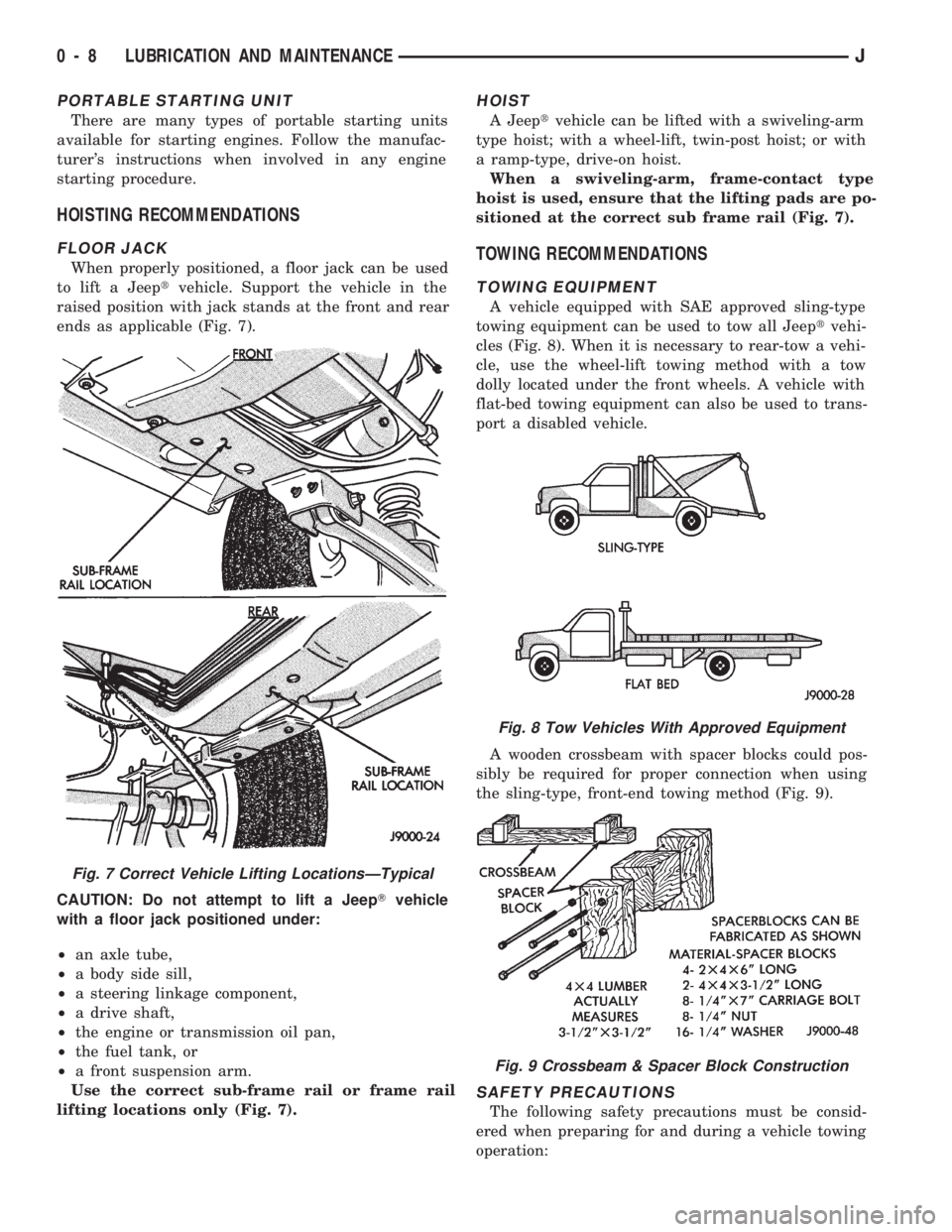
When properly positioned, a floor jack can be used
to lift a Jeeptvehicle. Support the vehicle in the
raised position with jack stands at the front and rear
ends as applicable (Fig. 7).
CAUTION: Do not attempt to lift a JeepTvehicle
with a floor jack positioned under:
²an axle tube,
²a body side sill,
²a steering linkage component,
²a drive shaft,
²the engine or transmission oil pan,
²the fuel tank, or
²a front suspension arm.
Use the correct sub-frame rail or frame rail
lifting locations only (Fig. 7).
HOIST
A Jeeptvehicle can be lifted with a swiveling-arm
type hoist; with a wheel-lift, twin-post hoist; or with
a ramp-type, drive-on hoist.
When a swiveling-arm, frame-contact type
hoist is used, ensure that the lifting pads are po-
sitioned at the correct sub frame rail (Fig. 7).
TOWING RECOMMENDATIONS
TOWING EQUIPMENT
A vehicle equipped with SAE approved sling-type
towing equipment can be used to tow all Jeeptvehi-
cles (Fig. 8). When it is necessary to rear-tow a vehi-
cle, use the wheel-lift towing method with a tow
dolly located under the front wheels. A vehicle with
flat-bed towing equipment can also be used to trans-
port a disabled vehicle.
A wooden crossbeam with spacer blocks could pos-
sibly be required for proper connection when using
the sling-type, front-end towing method (Fig. 9).
SAFETY PRECAUTIONS
The following safety precautions must be consid-
ered when preparing for and during a vehicle towing
operation:
Fig. 7 Correct Vehicle Lifting LocationsÐTypical
Fig. 8 Tow Vehicles With Approved Equipment
Fig. 9 Crossbeam & Spacer Block Construction
0 - 8 LUBRICATION AND MAINTENANCEJ
Page 10 of 1784
²if the vehicle is damaged, secure the loose and pro-
truding parts;
²always use a safety chain system that is indepen-
dent of the lifting and towing equipment;
²do not allow any of the towing equipment to con-
tact the disabled vehicle's fuel tank;
²do not allow anyone to be under the disabled vehi-
cle while it is lifted by the towing equipment;
²do not allow passengers to ride in a vehicle being
towed;
²always observe all state and local laws involving
warning signals, night illumination, speed, etc.
²do not attempt a towing operation that could jeop-
ardize the safety of the operator, bystanders or other
motorists;
²do not exceed a towing speed of 48 km/h (30 mph);
²avoid towing distances of more than 24 km (15
miles) whenever possible; and
²do not attach tow chains or a tow sling to a
bumper, the steering linkage, the universal joints,
the constant velocity (CV) joints, or a drive shaft.
CLEARANCES AND RAMP ANGLE
SURFACE CLEARANCE
The end of the disabled vehicle that is attached to
the tow vehicle should be lifted a minimum of 10 cm
or four inches off the surface. Inspect to ensure that
the opposite end of the disabled vehicle has clearance
from the surface.
RAMP ANGLEÐFLAT-BED TOWING
If a vehicle with flat-bed towing equipment is used,
the approach ramp angle should not exceed 15 de-
grees.
SLING-TYPE, FRONT-END TOWING
XJ VEHICLES
Use the following guidelines when the tow vehicle
is attached to the front end of a disabled vehicle.
(1) Always tow with the front wheels lifted off the
surface and turned all the way to the right.
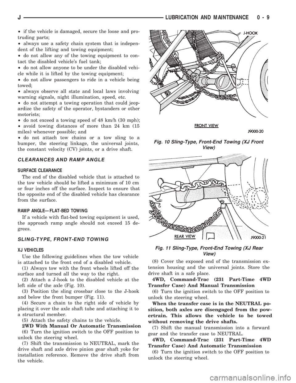
(2) Attach a J-hook to the disabled vehicle at the
left side of the axle (Fig. 10).
(3) Position the sling crossbar close to the J-hook
and below the front bumper (Fig. 11).
(4) Secure a chain to the right side of vehicle by
placing it over the axle shaft tube and attaching it to
a structural member.
(5) Attach the safety chains to the vehicle.
2WD With Manual Or Automatic Transmission
(6) Turn the ignition switch to the OFF position to
unlock the steering wheel.
(7) Shift the transmission to NEUTRAL, mark the
drive shaft and axle drive pinion gear shaft yoke for
installation reference. Remove the drive shaft from
the vehicle.(8) Cover the exposed end of the transmission ex-
tension housing and the universal joints. Store the
drive shaft in a safe place.
4WD, Command-Trac (231 Part-Time 4WD
Transfer Case) And Manual Transmission
(6) Turn the ignition switch to the OFF position to
unlock the steering wheel.
When the transfer case is in the NEUTRAL po-
sition, both axles are disengaged from the pow-
ertrain. This allows the vehicle to be towed
without removing the drive shafts.
(7) Shift the manual transmission into a forward
gear and the transfer case to NEUTRAL.
4WD, Command-Trac (231 Part-Time 4WD
Transfer Case) And Automatic Transmission
(6) Turn the ignition switch to the OFF position to
unlock the steering wheel.
Fig. 10 Sling-Type, Front-End Towing (XJ Front
View)
Fig. 11 Sling-Type, Front-End Towing (XJ Rear
View)
JLUBRICATION AND MAINTENANCE 0 - 9
Page 11 of 1784
When the transfer case is in the NEUTRAL po-
sition, both axles are disengaged from the pow-
ertrain. This allows the vehicle to be towed
without removing the drive shafts.
(7) Shift the automatic transmission to PARK and
the transfer case to NEUTRAL.
4WD, Selec-Trac (242 Full-Time 4WD Transfer
Case) And Automatic Transmission
(6) Turn the ignition switch to the OFF position to
unlock the steering wheel.
When the transfer case is in the NEUTRAL po-
sition, both axles are disengaged from the pow-
ertrain. This allows the vehicle to be towed
without removing the drive shafts.
(7) Shift the automatic transmission to PARK and
the transfer case to NEUTRAL.
YJ VEHICLES
Use the following guidelines when the tow vehicle
is attached to the front of a disabled vehicle.
(1) Always tow with the front wheels lifted off the
surface and turned all the way to the right.
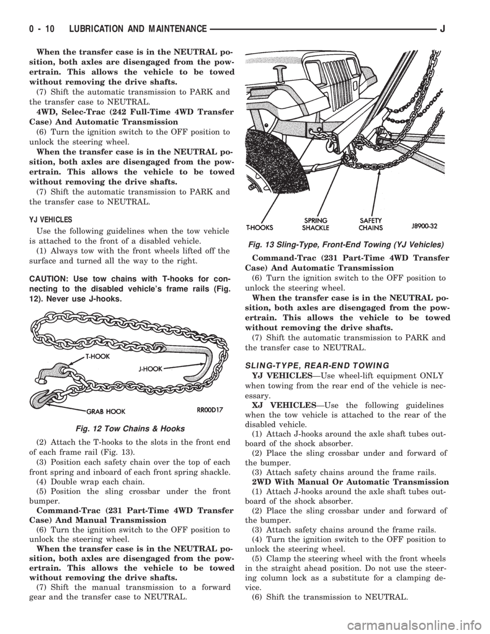
CAUTION: Use tow chains with T-hooks for con-
necting to the disabled vehicle's frame rails (Fig.
12). Never use J-hooks.
(2) Attach the T-hooks to the slots in the front end
of each frame rail (Fig. 13).
(3) Position each safety chain over the top of each
front spring and inboard of each front spring shackle.
(4) Double wrap each chain.
(5) Position the sling crossbar under the front
bumper.
Command-Trac (231 Part-Time 4WD Transfer
Case) And Manual Transmission
(6) Turn the ignition switch to the OFF position to
unlock the steering wheel.
When the transfer case is in the NEUTRAL po-
sition, both axles are disengaged from the pow-
ertrain. This allows the vehicle to be towed
without removing the drive shafts.
(7) Shift the manual transmission to a forward
gear and the transfer case to NEUTRAL.Command-Trac (231 Part-Time 4WD Transfer
Case) And Automatic Transmission
(6) Turn the ignition switch to the OFF position to
unlock the steering wheel.
When the transfer case is in the NEUTRAL po-
sition, both axles are disengaged from the pow-
ertrain. This allows the vehicle to be towed
without removing the drive shafts.
(7) Shift the automatic transmission to PARK and
the transfer case to NEUTRAL.
SLING-TYPE, REAR-END TOWING
YJ VEHICLESÐUse wheel-lift equipment ONLY
when towing from the rear end of the vehicle is nec-
essary.
XJ VEHICLESÐUse the following guidelines
when the tow vehicle is attached to the rear of the
disabled vehicle.
(1) Attach J-hooks around the axle shaft tubes out-
board of the shock absorber.
(2) Place the sling crossbar under and forward of
the bumper.
(3) Attach safety chains around the frame rails.
2WD With Manual Or Automatic Transmission
(1) Attach J-hooks around the axle shaft tubes out-
board of the shock absorber.
(2) Place the sling crossbar under and forward of
the bumper.
(3) Attach safety chains around the frame rails.
(4) Turn the ignition switch to the OFF position to
unlock the steering wheel.
(5) Clamp the steering wheel with the front wheels
in the straight ahead position. Do not use the steer-
ing column lock as a substitute for a clamping de-
vice.
(6) Shift the transmission to NEUTRAL.
Fig. 12 Tow Chains & Hooks
Fig. 13 Sling-Type, Front-End Towing (YJ Vehicles)
0 - 10 LUBRICATION AND MAINTENANCEJ
Page 12 of 1784
4WD, Command-Trac (231 Part-Time 4WD
Transfer Case) And Manual Transmission
(1) Attach J-hooks around the axle shaft tubes out-
board of the shock absorber.
(2) Place the sling crossbar under and forward of
the bumper.
(3) Attach safety chains around the frame rails.
(4) Turn the ignition switch to the OFF position to
unlock the steering column.
(5) Clamp the steering wheel with the front wheels
in the straight ahead position. Do not use the steer-
ing column lock as a substitute for a clamping de-
vice.
When the transfer case is in the NEUTRAL po-
sition, both axles are disengaged from the pow-
ertrain. This allows the vehicle to be towed
without removing the drive shafts.
(6) Shift the transmission to a forward gear and
the transfer case to NEUTRAL.
4WD, Command-Trac (231 Part-Time 4WD
Transfer Case) And Automatic Transmission
(1) Attach J-hooks around the axle shaft tubes out-
board of the shock absorber.
(2) Place the sling crossbar under and forward of
the bumper.
(3) Attach safety chains around the frame rails.
(4) Turn the ignition switch to the OFF position to
unlock the steering column.
(5) Clamp the steering wheel with the front wheels
in the straight ahead position. Do not use the steer-
ing column lock as a substitute for a clamping de-
vice.
When the transfer case is in the NEUTRAL po-
sition, both axles are disengaged from the pow-
ertrain. This allows the vehicle to be towed
without removing the drive shafts.
(6) Shift the transmission to PARK and the trans-
fer case to NEUTRAL.
4WD, Selec-Trac (242 Full-Time 4WD Transfer
Case) And Automatic Transmission
(1) Attach J-hooks around the axle shaft tubes out-
board of the shock absorber.
(2) Place the sling crossbar under and forward of
the bumper.
(3) Attach safety chains around the frame rails.
(4) Turn the ignition switch to the OFF position to
unlock the steering column.
(5) Clamp the steering wheel with the front wheels
in the straight ahead position. Do not use the steer-
ing column lock as a substitute for a clamping de-
vice.
When the transfer case is in the NEUTRAL po-
sition, both axles are disengaged from the pow-
ertrain. This allows the vehicle to be towed
without removing the drive shafts.
(6) Shift the transmission to PARK and the trans-
fer case to NEUTRAL.TOWING WHEN IGNITION KEYS ARE NOT
AVAILABLE
VEHICLE DOORS UNLOCKED
2WD Vehicles
Either one of two methods can be used:
²tow the vehicle with the drive shaft removed (refer
to Sling-Type, Front-End Towing); or
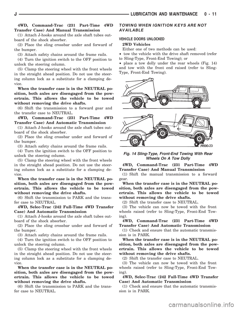
²place a tow dolly under the rear wheels (Fig. 14)
and tow with the front end raised (refer to Sling-
Type, Front-End Towing).
4WD, Command-Trac (231 Part-Time 4WD
Transfer Case) And Manual Transmission
(1) Shift the manual transmission to a forward
gear.
When the transfer case is in the NEUTRAL po-
sition, both axles are disengaged from the pow-
ertrain. This allows the vehicle to be towed
without removing the drive shafts.
(2) Shift the transfer case to NEUTRAL.
(3) The vehicle can now be towed with the front
wheels raised (refer to Sling-Type, Front-End Tow-
ing).
4WD, Command-Trac (231 Part-Time 4WD
Transfer Case) And Automatic Transmission
(1) Check and ensure that the automatic transmis-
sion is in PARK.
When the transfer case is in the NEUTRAL po-
sition, both axles are disengaged from the pow-
ertrain. This allows the vehicle to be towed
without removing the drive shafts.
(2) Shift the transfer case to NEUTRAL.
(3) The vehicle can now be towed with the front
wheels raised (refer to Sling-Type, Front-End Tow-
ing).
4WD, Selec-Trac (242 Full-Time 4WD Transfer
Case) And Automatic Transmission
(1) Check and ensure that the automatic transmis-
sion is in PARK.
Fig. 14 Sling-Type, Front-End Towing With Rear
Wheels On A Tow Dolly
JLUBRICATION AND MAINTENANCE 0 - 11
Page 31 of 1784

CHASSIS AND BODY COMPONENTS
INDEX
page page
Body Components........................ 34
Chassis Component and Wheel Bearing
Lubricants............................ 30
Front Wheel Bearings..................... 31
Headlamps............................. 35Manual Steering GearÐYJ Vehicles.......... 32
Power Brake System...................... 32
Power Steering System.................... 31
Steering Linkage and Ball Studs............. 30
Tires.................................. 34
CHASSIS COMPONENT AND WHEEL BEARING
LUBRICANTS
The chassis component and wheel bearing lubri-
cants that are recommended for Jeeptvehicles are
identified by the NLGI Certification Symbol (Fig. 1).
The symbol contains a coded designation that identi-
fies the usage and quality of the lubricant.
The letterGdesignates wheel bearing lubricant.
LetterLdesignates chassis lubricant. When the let-
ters are combined the lubricant can be used for dual
applications. The suffix lettersCandBdesignate the
level of the lubricant for the application. The letterC
represents level available for wheel bearing lubricant
(G) and the letterBrepresents level available for
chassis lubricant (L).
STEERING LINKAGE AND BALL STUDS
RECOMMENDED MAINTENANCE
The general condition of the steering linkage (Fig.
2) should be inspected and the ball studs should be
lubricated:
²2WD vehicles Ð after each 24 000-km (15,000-
miles) or six-months interval of vehicle operation has
elapsed; or
²4WD vehicles Ð after each 12 000-km (7,500-
miles) or six-months interval of vehicle operation has
elapsed.
LUBRICANT SPECIFICATION
Steering linkage should be lubricated with a dual-
purpose, lithium-base lubricant that is identified as
NLGI GC-LB lubricant.
INSPECTION/LUBRICATION
(1) Inspect the steering linkage. Examine the tie
rods and the drag link for bending, and the ball
studs for looseness and excessive wear.
(2) Replace, as necessary, all torn/ruptured ball-
stud seals and damaged/defective steering linkage
components.
CAUTION: Use care to prevent lubricant from con-
tacting the brake rotors.
(3) Lubricate the ball studs:
²clean the tips of the Zerk type lubrication fittings
on the tie-rod and drag-link ball-stud ends to avoid
lubricant contamination;
²lubricate the ball studs with high quality, dual-
purpose, lithium base chassis/wheel bearing lubri-
cant (NLGI GC-LB lubricant);
²cease the lubricant pressure when lubricant begins
to freely exit the base of the seal, or if the seal be-
gins to expand; and
²wipe the excess lubricant from the exterior sur-
faces of the ball joints and the adjacent surfaces.
Fig. 1 NLGI Lubricant Container Certification/
Identification Symbol
Fig. 2 Steering Components (XJ)ÐTypical
0 - 30 LUBRICATION AND MAINTENANCEJ
Page 32 of 1784
FRONT WHEEL BEARINGS
Only 2WD XJ vehicles are equipped with front
wheel bearings. XJ vehicles have semi-floating axle
shafts and axle shaft bearings that are lubricated via
differential lube oil.
RECOMMENDED MAINTENANCEÐ2WD XJ
VEHICLES
The front wheel bearings should be lubricated (re-
packed) at the same time as front brake pad/caliper
service is conducted.
LUBRICANT SPECIFICATION
Wheel bearings should be lubricated with a lubri-
cant that is identified as NLGI GC-LB lubricant.
INSPECTION/LUBRICATION
(1) Remove the wheel/tire and the disc brake cali-
per.Do not disconnect the caliper brake fluid
hose unless the caliper must also be removed for
maintenance. Support the caliper with a hanger
to prevent brake fluid hose damage.
(2) Remove the dust cap, the cotter pin, the nut re-
tainer, the adjustment nut, and the thrust washer
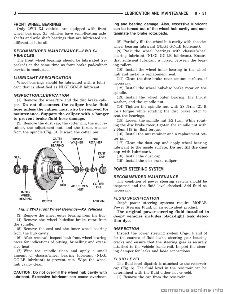
from the spindle (Fig. 3). Discard the cotter pin.
(3) Remove the wheel outer bearing from the hub.
(4) Remove the wheel hub/disc brake rotor from
the spindle.
(5) Remove the seal and the inner wheel bearing
from the hub cavity.
(6) After removal, inspect both front wheel bearing
races for indications of pitting, brinelling and exces-
sive heat.
(7) Wipe the spindle clean and apply a small
amount of chassis/wheel bearing lubricant (NLGI
GC-LB lubricant) to prevent rust. Wipe the wheel
hub cavity clean.
CAUTION: Do not over-fill the wheel hub cavity with
lubricant. Excessive lubricant can cause overheat-ing and bearing damage. Also, excessive lubricant
can be forced out of the wheel hub cavity and con-
taminate the brake rotor/pads.
(8) Partially fill the wheel hub cavity with chassis/
wheel bearing lubricant (NLGI GC-LB lubricant).
(9) Pack the wheel bearings with chassis/wheel
bearing lubricant (NLGI GC-LB lubricant). Ensure
that sufficient lubricant is forced between the bear-
ing rollers.
(10) Install the wheel inner bearing in the wheel
hub and install a replacement seal.
(11) Clean the disc brake rotor contact surfaces, if
necessary.
(12) Install the wheel hub/disc brake rotor on the
spindle.
(13) Install the wheel outer bearing, the thrust
washer, and the spindle nut.
(14) Tighten the spindle nut with 28 NIm (21 ft.
lbs.) torque while rotating the disc brake rotor to
seat the bearings.
(15) Loosen the spindle nut 1/2 turn. While rotat-
ing the disc brake rotor, tighten the spindle nut with
2NIm (19 in. lbs.) torque.
(16) Install the nut retainer and a replacement cot-
ter pin.
(17) Clean the dust cap and apply wheel bearing
lubricant to the inside surface.Do not fill the dust
cap with lubricant.
(18) Install the dust cap.
(19) Install the disc brake caliper.
POWER STEERING SYSTEM
RECOMMENDED MAINTENANCE
The condition of power steering system should be
inspected and the fluid level checked. Add fluid as
necessary.
FLUID SPECIFICATION
Jeeptpower steering systems require MOPAR
Power Steering Fluid, or an equivalent product.
The original power steering fluid installed in
Jeeptvehicles includes black-light leak detec-
tion dye.
INSPECTION
Inspect the power steering system (Figs. 4 and 5)
for the sources of fluid leaks, steering gear housing
cracks and ensure that the steering gear is securely
attached to the vehicle frame rail. Inspect the steer-
ing damper for leaks and loose connections.
FLUID LEVEL
The fluid level dipstick is attached to the reservoir
cap (Fig. 6). The fluid level in the reservoir can be
determined with the fluid either hot or cold.
(1) Remove the cap from the reservoir.
Fig. 3 2WD Front Wheel BearingsÐXJ Vehicles
JLUBRICATION AND MAINTENANCE 0 - 31
Page 38 of 1784
FRONT SUSPENSION AND AXLE
CONTENTS
page page
AXLE NOISE/VIBRATION DIAGNOSIS....... 16
FRONT WHEEL ALIGNMENT............... 5
GENERAL INFORMATION.................. 1
MODEL 30 AXLE AND TUBE AXLE (2WD) . . 20TORQUE SPECIFICATIONS................ 47
XJ FRONT SUSPENSION................. 10
YJ FRONT SUSPENSION................. 13
GENERAL INFORMATION
FRONT SUSPENSION
XJ VEHICLES
The Cherokee front suspension is a link/coil design
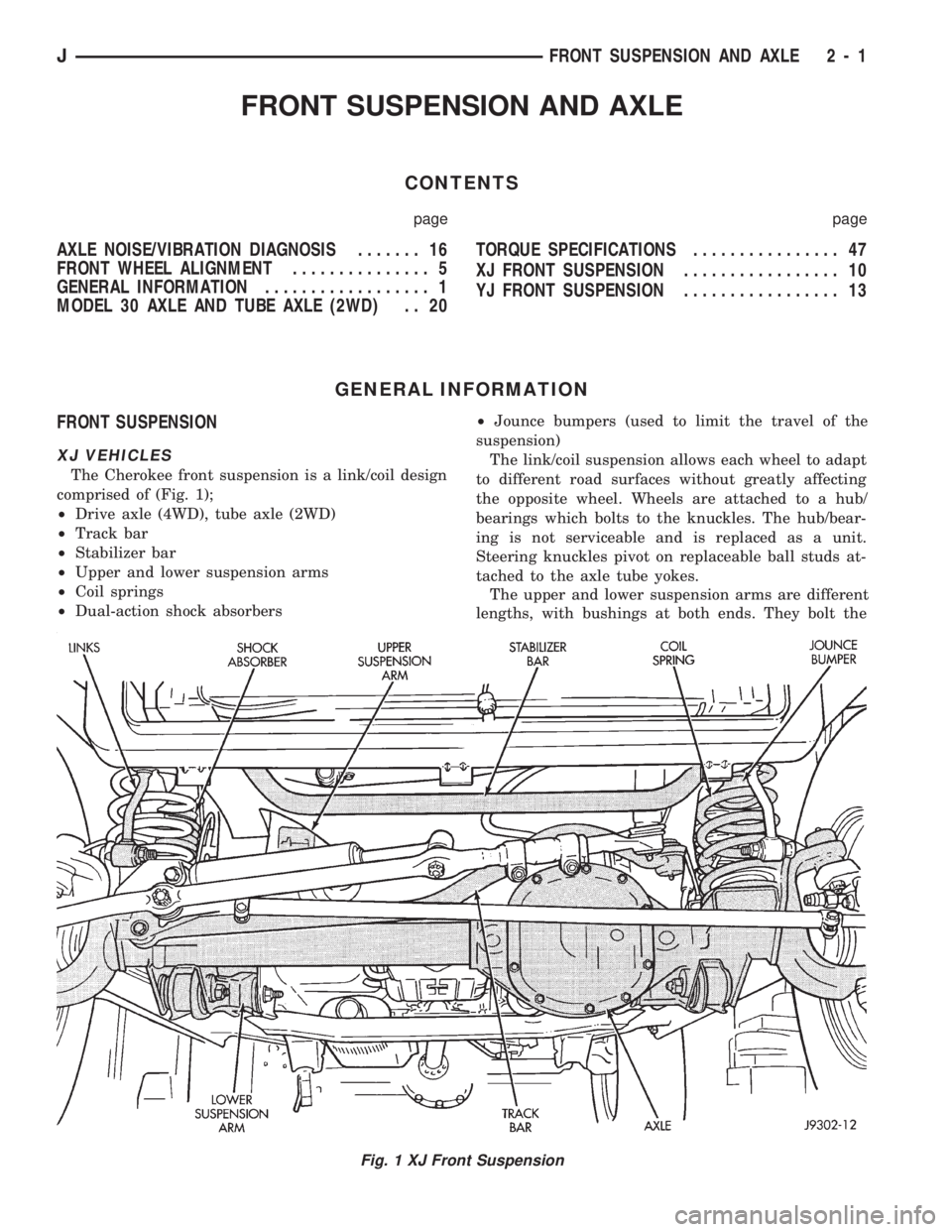
comprised of (Fig. 1);
²Drive axle (4WD), tube axle (2WD)
²Track bar
²Stabilizer bar
²Upper and lower suspension arms
²Coil springs
²Dual-action shock absorbers²Jounce bumpers (used to limit the travel of the
suspension)
The link/coil suspension allows each wheel to adapt
to different road surfaces without greatly affecting
the opposite wheel. Wheels are attached to a hub/
bearings which bolts to the knuckles. The hub/bear-
ing is not serviceable and is replaced as a unit.
Steering knuckles pivot on replaceable ball studs at-
tached to the axle tube yokes.
The upper and lower suspension arms are different
lengths, with bushings at both ends. They bolt the
Fig. 1 XJ Front Suspension
JFRONT SUSPENSION AND AXLE 2 - 1