Page 388 of 1784
HORN SWITCH (HORN PAD) REPLACEMENT
(1) Disconnect negative cable from battery.
(2) Remove horn button by pulling straight up.
(3) Remove horn button components (Fig. 4).
(4) To install the switch, reverse the removal pro-
cedures.
(5) Connect negative cable to battery.
TORQUE SPECIFICATIONS
Fig. 4 Steering Wheel Removal/Installation
JHORNS 8G - 3
Page 398 of 1784
SERVICE PROCEDURES
INDEX
page page
Servo Cable Replacement................... 9
Speed Control Servo Replacement............ 9Speed Control Switch Replacement............ 9
SPEED CONTROL SERVO REPLACEMENT
REMOVAL
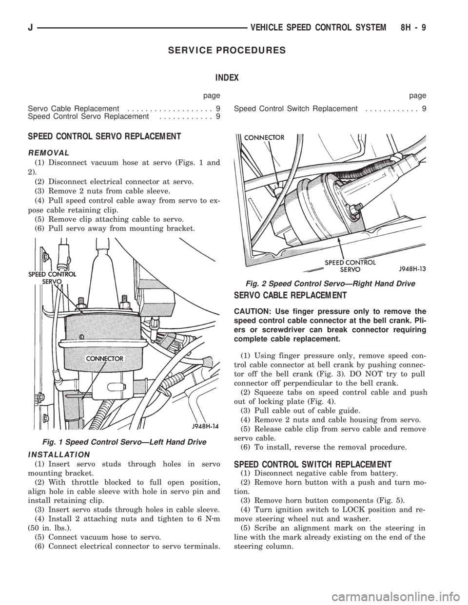
(1) Disconnect vacuum hose at servo (Figs. 1 and
2).
(2) Disconnect electrical connector at servo.
(3) Remove 2 nuts from cable sleeve.
(4) Pull speed control cable away from servo to ex-
pose cable retaining clip.
(5) Remove clip attaching cable to servo.
(6) Pull servo away from mounting bracket.
INSTALLATION
(1) Insert servo studs through holes in servo
mounting bracket.
(2) With throttle blocked to full open position,
align hole in cable sleeve with hole in servo pin and
install retaining clip.
(3)
Insert servo studs through holes in cable sleeve.
(4) Install 2 attaching nuts and tighten to 6 Nzm
(50 in. lbs.).
(5) Connect vacuum hose to servo.
(6) Connect electrical connector to servo terminals.
SERVO CABLE REPLACEMENT
CAUTION: Use finger pressure only to remove the
speed control cable connector at the bell crank. Pli-
ers or screwdriver can break connector requiring
complete cable replacement.
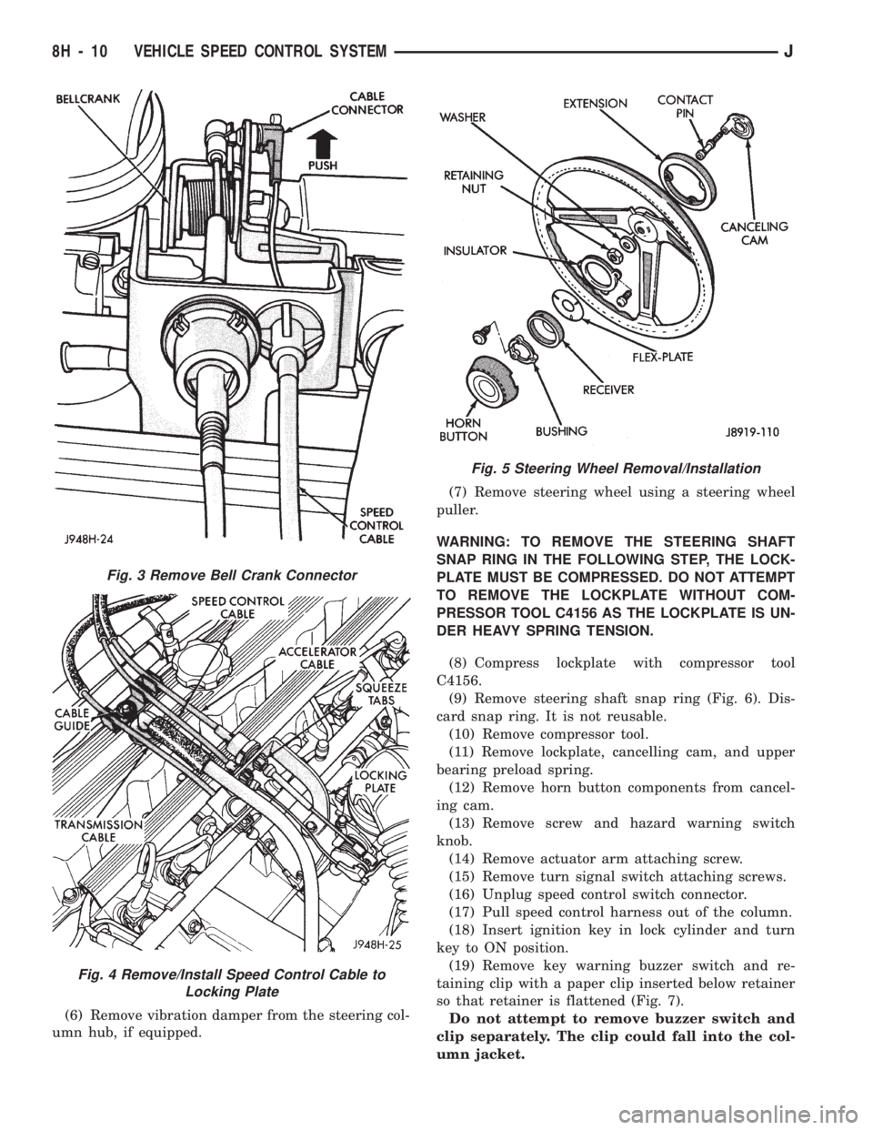
(1) Using finger pressure only, remove speed con-
trol cable connector at bell crank by pushing connec-
tor off the bell crank (Fig. 3). DO NOT try to pull
connector off perpendicular to the bell crank.
(2) Squeeze tabs on speed control cable and push
out of locking plate (Fig. 4).
(3) Pull cable out of cable guide.
(4) Remove 2 nuts and cable housing from servo.
(5) Release cable clip from servo cable and remove
servo cable.
(6) To install, reverse the removal procedure.
SPEED CONTROL SWITCH REPLACEMENT
(1) Disconnect negative cable from battery.
(2) Remove horn button with a push and turn mo-
tion.
(3) Remove horn button components (Fig. 5).
(4) Turn ignition switch to LOCK position and re-
move steering wheel nut and washer.
(5) Scribe an alignment mark on the steering in
line with the mark already existing on the end of the
steering column.
Fig. 2 Speed Control ServoÐRight Hand Drive
Fig. 1 Speed Control ServoÐLeft Hand Drive
JVEHICLE SPEED CONTROL SYSTEM 8H - 9
Page 399 of 1784
(6) Remove vibration damper from the steering col-
umn hub, if equipped.(7) Remove steering wheel using a steering wheel
puller.
WARNING: TO REMOVE THE STEERING SHAFT
SNAP RING IN THE FOLLOWING STEP, THE LOCK-
PLATE MUST BE COMPRESSED. DO NOT ATTEMPT
TO REMOVE THE LOCKPLATE WITHOUT COM-
PRESSOR TOOL C4156 AS THE LOCKPLATE IS UN-
DER HEAVY SPRING TENSION.
(8) Compress lockplate with compressor tool
C4156.
(9) Remove steering shaft snap ring (Fig. 6). Dis-
card snap ring. It is not reusable.
(10) Remove compressor tool.
(11) Remove lockplate, cancelling cam, and upper
bearing preload spring.
(12) Remove horn button components from cancel-
ing cam.
(13) Remove screw and hazard warning switch
knob.
(14) Remove actuator arm attaching screw.
(15) Remove turn signal switch attaching screws.
(16) Unplug speed control switch connector.
(17) Pull speed control harness out of the column.
(18) Insert ignition key in lock cylinder and turn
key to ON position.
(19) Remove key warning buzzer switch and re-
taining clip with a paper clip inserted below retainer
so that retainer is flattened (Fig. 7).
Do not attempt to remove buzzer switch and
clip separately. The clip could fall into the col-
umn jacket.
Fig. 3 Remove Bell Crank Connector
Fig. 4 Remove/Install Speed Control Cable to
Locking Plate
Fig. 5 Steering Wheel Removal/Installation
8H - 10 VEHICLE SPEED CONTROL SYSTEMJ
Page 401 of 1784
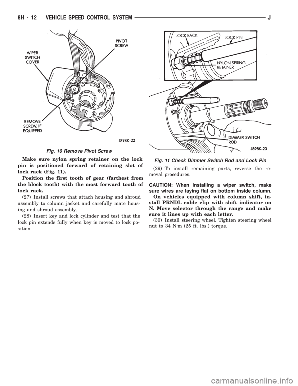
Make sure nylon spring retainer on the lock
pin is positioned forward of retaining slot of
lock rack (Fig. 11).
Position the first tooth of gear (farthest from
the block tooth) with the most forward tooth of
lock rack.
(27) Install screws that attach housing and shroud
assembly to column jacket and carefully mate hous-
ing and shroud assembly.
(28) Insert key and lock cylinder and test that the
lock pin extends fully when key is moved to lock po-
sition.(29) To install remaining parts, reverse the re-
moval procedures.
CAUTION: When installing a wiper switch, make
sure wires are laying flat on bottom inside column.
On vehicles equipped with column shift, in-
stall PRNDL cable clip with shift indicator on
N. Move selector through the range and make
sure it lines up with each letter.
(30) Install steering wheel. Tighten steering wheel
nut to 34 Nzm (25 ft. lbs.) torque.
Fig. 10 Remove Pivot Screw
Fig. 11 Check Dimmer Switch Rod and Lock Pin
8H - 12 VEHICLE SPEED CONTROL SYSTEMJ
Page 404 of 1784
TURN/HAZARD SWITCH REPLACEMENT - ALL MODELS
(1) Disconnect negative cable from battery.
(2) Remove the horn button with a push and turn
motion.
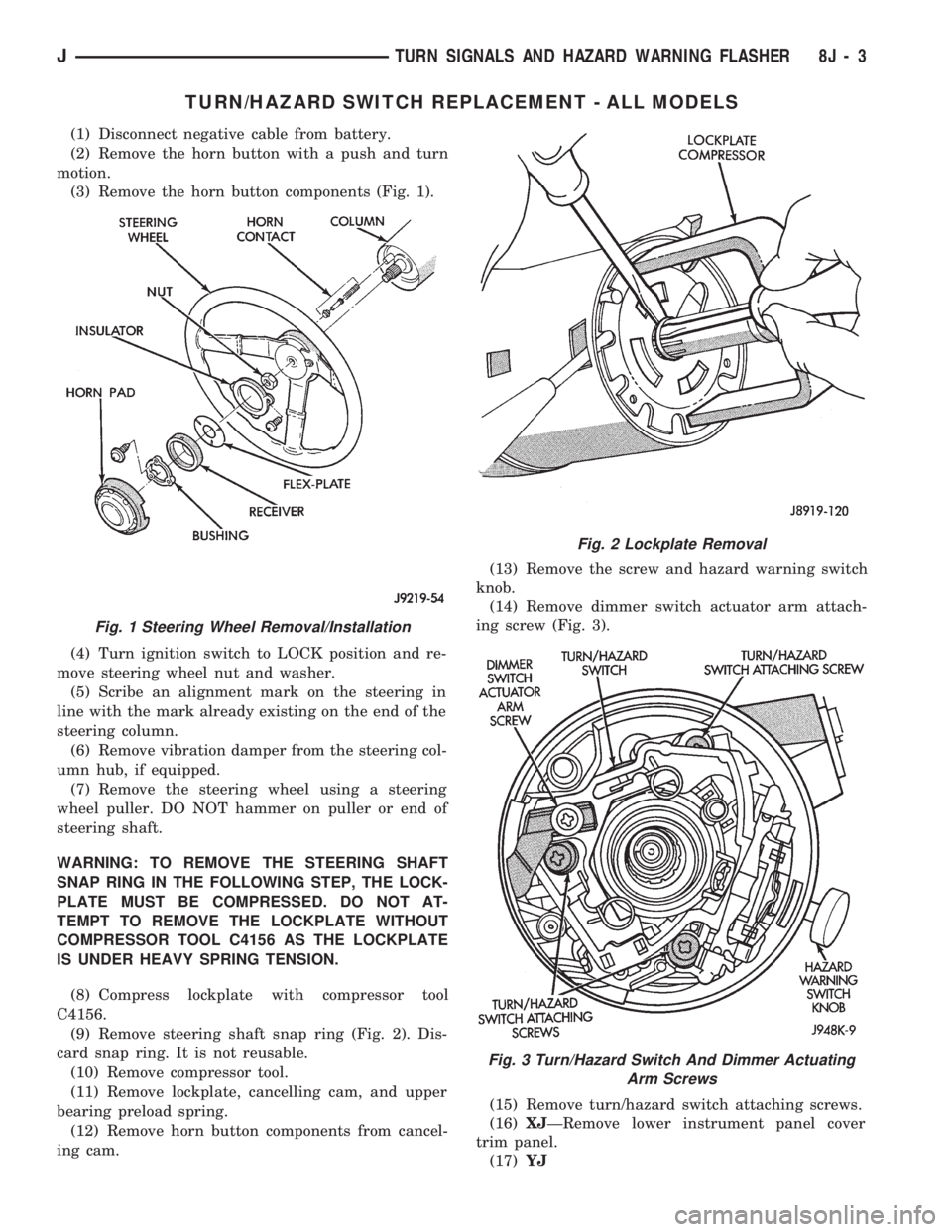
(3) Remove the horn button components (Fig. 1).
(4) Turn ignition switch to LOCK position and re-
move steering wheel nut and washer.
(5) Scribe an alignment mark on the steering in
line with the mark already existing on the end of the
steering column.
(6) Remove vibration damper from the steering col-
umn hub, if equipped.
(7) Remove the steering wheel using a steering
wheel puller. DO NOT hammer on puller or end of
steering shaft.
WARNING: TO REMOVE THE STEERING SHAFT
SNAP RING IN THE FOLLOWING STEP, THE LOCK-
PLATE MUST BE COMPRESSED. DO NOT AT-
TEMPT TO REMOVE THE LOCKPLATE WITHOUT
COMPRESSOR TOOL C4156 AS THE LOCKPLATE
IS UNDER HEAVY SPRING TENSION.
(8) Compress lockplate with compressor tool
C4156.
(9) Remove steering shaft snap ring (Fig. 2). Dis-
card snap ring. It is not reusable.
(10) Remove compressor tool.
(11) Remove lockplate, cancelling cam, and upper
bearing preload spring.
(12) Remove horn button components from cancel-
ing cam.(13) Remove the screw and hazard warning switch
knob.
(14) Remove dimmer switch actuator arm attach-
ing screw (Fig. 3).
(15) Remove turn/hazard switch attaching screws.
(16)XJÐRemove lower instrument panel cover
trim panel.
(17)YJ
Fig. 1 Steering Wheel Removal/Installation
Fig. 2 Lockplate Removal
Fig. 3 Turn/Hazard Switch And Dimmer Actuating
Arm Screws
JTURN SIGNALS AND HAZARD WARNING FLASHER 8J - 3
Page 405 of 1784

(a) Remove 6 housing screws (Fig. 4).
(b) Slide housing toward steering wheel.
(18) Remove cover under column.
(19) If vehicle is equipped with a column shift, re-
move PRNDL cable clip (Fig. 5).
(20) Remove 2 nuts holding steering column
bracket to brake sled (Fig. 6).
(21) Remove 4 bolts holding steering column
bracket to column.
(22) Loosen column brace mounting nut at drivers
side kick panel. This will allow column to drop.(23) Push turn/hazard connector up and out of
steering column connector (Fig. 7).
(24) Pry up locking tabs of steering column connec-
tor and remove connector from column bracket.
(25) Tape connector to wires as shown (Fig. 8).
(26) Remove plastic harness cover by pulling it up
and over the weld nuts then open and slide the cover
off the harness (Fig. 9).
Fig. 4 Instrument Housing Removal/InstallationÐYJ
Fig. 5 PRNDL Cable Clip Removal/Installation
Fig. 6 Lower Steering Column
Fig. 7 Turn/Hazard Switch And Steering Column
Connectors
8J - 4 TURN SIGNALS AND HAZARD WARNING FLASHERJ
Page 422 of 1784
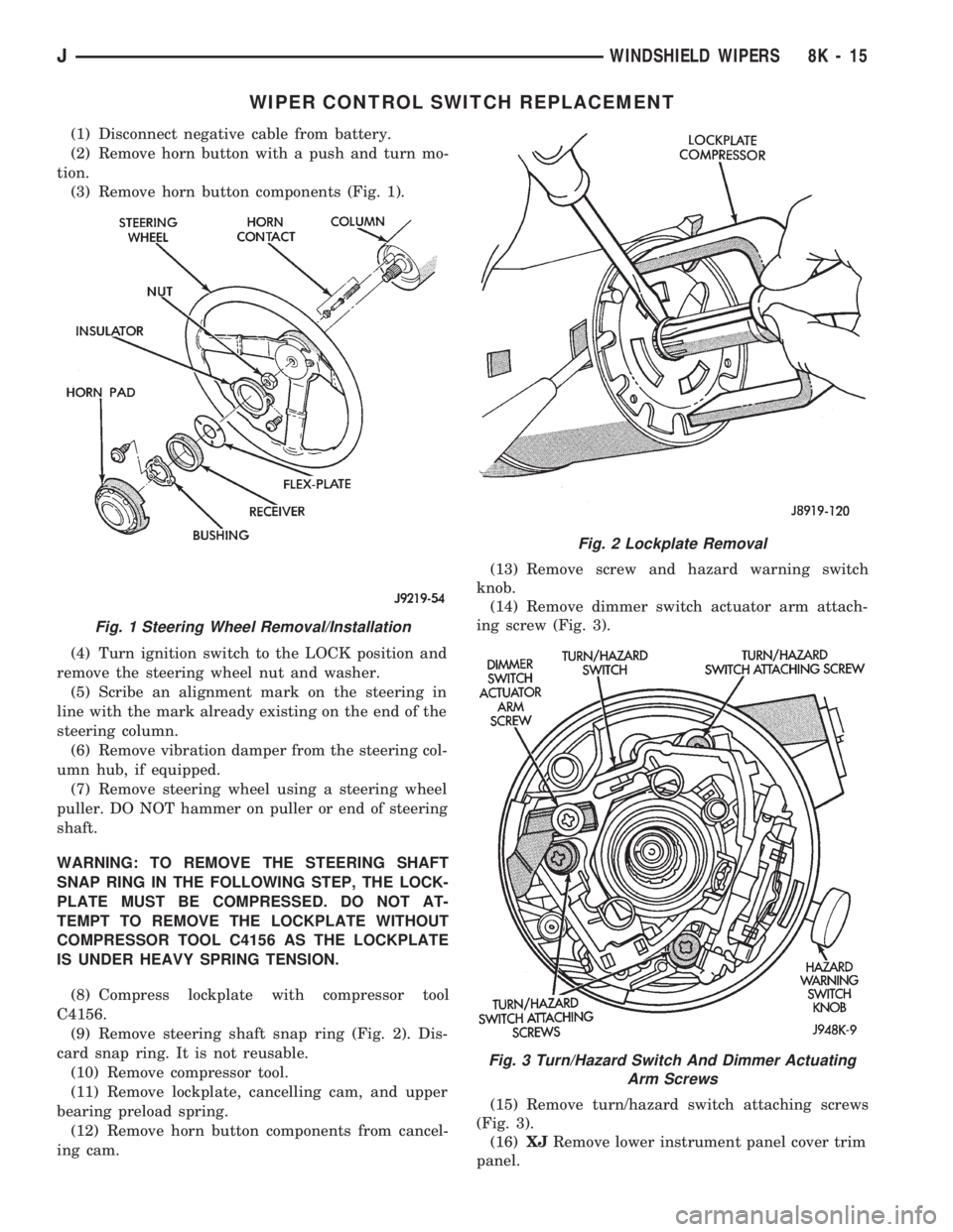
WIPER CONTROL SWITCH REPLACEMENT
(1) Disconnect negative cable from battery.
(2) Remove horn button with a push and turn mo-
tion.
(3) Remove horn button components (Fig. 1).
(4) Turn ignition switch to the LOCK position and
remove the steering wheel nut and washer.
(5) Scribe an alignment mark on the steering in
line with the mark already existing on the end of the
steering column.
(6) Remove vibration damper from the steering col-
umn hub, if equipped.
(7) Remove steering wheel using a steering wheel
puller. DO NOT hammer on puller or end of steering
shaft.
WARNING: TO REMOVE THE STEERING SHAFT
SNAP RING IN THE FOLLOWING STEP, THE LOCK-
PLATE MUST BE COMPRESSED. DO NOT AT-
TEMPT TO REMOVE THE LOCKPLATE WITHOUT
COMPRESSOR TOOL C4156 AS THE LOCKPLATE
IS UNDER HEAVY SPRING TENSION.
(8) Compress lockplate with compressor tool
C4156.
(9) Remove steering shaft snap ring (Fig. 2). Dis-
card snap ring. It is not reusable.
(10) Remove compressor tool.
(11) Remove lockplate, cancelling cam, and upper
bearing preload spring.
(12) Remove horn button components from cancel-
ing cam.(13) Remove screw and hazard warning switch
knob.
(14) Remove dimmer switch actuator arm attach-
ing screw (Fig. 3).
(15) Remove turn/hazard switch attaching screws
(Fig. 3).
(16)XJRemove lower instrument panel cover trim
panel.
Fig. 1 Steering Wheel Removal/Installation
Fig. 2 Lockplate Removal
Fig. 3 Turn/Hazard Switch And Dimmer Actuating
Arm Screws
JWINDSHIELD WIPERS 8K - 15
Page 423 of 1784
(17)YJ
(a) Remove 6 shroud screws (Fig. 4).
(b) Slide shroud toward steering wheel.
(18) Remove cover under column.
(19) If vehicle is equipped with a column shift, re-
move PRNDL cable clip (Fig. 5).
(20) Remove 2 nuts holding steering column
bracket to brake sled (Fig. 6).
(21) Remove 4 bolts holding steering column brace
to column.(22) Loosen column brace mounting nut at drivers
side kick panel. This will allow column to drop.
(23) Unplug wiper switch connector.
(24) Tape connector to wires (Fig. 7).
Fig. 4 Instrument Shroud Removal/InstallationÐYJ
Fig. 5 PRNDL Cable Clip Removal/Installation
Fig. 6 Lower Steering Column Mounting
Fig. 7 Tape Wiper Switch Connector
8K - 16 WINDSHIELD WIPERSJ