1994 JEEP CHEROKEE steering wheel
[x] Cancel search: steering wheelPage 61 of 1784
CAUTION: Never loosen the pinion gear nut to de-
crease the pinion gear bearing preload torque. If the
specified preload torque is exceeded, a new col-
lapsible spacer must be installed. The torque se-
quence will have to be repeated.
(4) Install a socket and inch-pound torque wrench
on the pinion nut.
(5) Rotate the shaft with the torque wrench and
note the torque.
Required preload torque is the amount re-
corded during removal plus an additional 0.56
Nzm (5 in. lbs.).
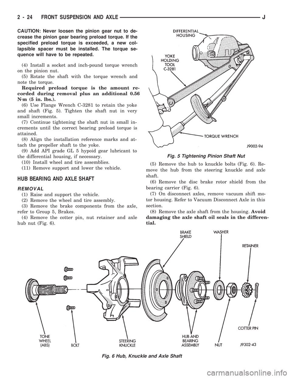
(6) Use Flange Wrench C-3281 to retain the yoke
and shaft (Fig. 5). Tighten the shaft nut in very
small increments.
(7) Continue tightening the shaft nut in small in-
crements until the correct bearing preload torque is
attained.
(8) Align the installation reference marks and at-
tach the propeller shaft to the yoke.
(9) Add API grade GL 5 hypoid gear lubricant to
the differential housing, if necessary.
(10) Install wheel and tire assemblies.
(11) Remove support and lower the vehicle.
HUB BEARING AND AXLE SHAFT
REMOVAL
(1) Raise and support the vehicle.
(2) Remove the wheel and tire assembly.
(3) Remove the brake components from the axle,
refer to Group 5, Brakes.
(4) Remove the cotter pin, nut retainer and axle
hub nut (Fig. 6).(5) Remove the hub to knuckle bolts (Fig. 6). Re-
move the hub from the steering knuckle and axle
shaft.
(6) Remove the disc brake rotor shield from the
bearing carrier (Fig. 6).
(7) On disconnect axles, remove vacuum shift mo-
tor housing. Refer to Vacuum Disconnect Axle in this
section.
(8) Remove the axle shaft from the housing.Avoid
damaging the axle shaft oil seals in the differen-
tial.
Fig. 5 Tightening Pinion Shaft Nut
Fig. 6 Hub, Knuckle and Axle Shaft
2 - 24 FRONT SUSPENSION AND AXLEJ
Page 108 of 1784
SPEED CONTROLÐPCM INPUT
The speed control system provides three separate
inputs to the powertrain control module (PCM); On/
Off, Set and Resume. The On/Off input informs the
PCM that the speed control system has been acti-
vated. The Set input informs the PCM that a fixed
vehicle speed has been selected. The Resume input
indicates to the PCM that the previous fixed speed is
requested.
The speed control operating range is from 50 km/h
to 142 km/h (35 to 85 mph). Inputs that effect speed
control operation are:
²Park/neutral switch
²Vehicle speed sensor
²Throttle position sensor
Refer to Group 8H for further speed control infor-
mation.
SENSOR RETURNÐPCM INPUT
Sensor Return provides a low noise ground refer-
ence for all system sensors.
THROTTLE POSITION SENSOR (TPS)ÐPCM INPUT
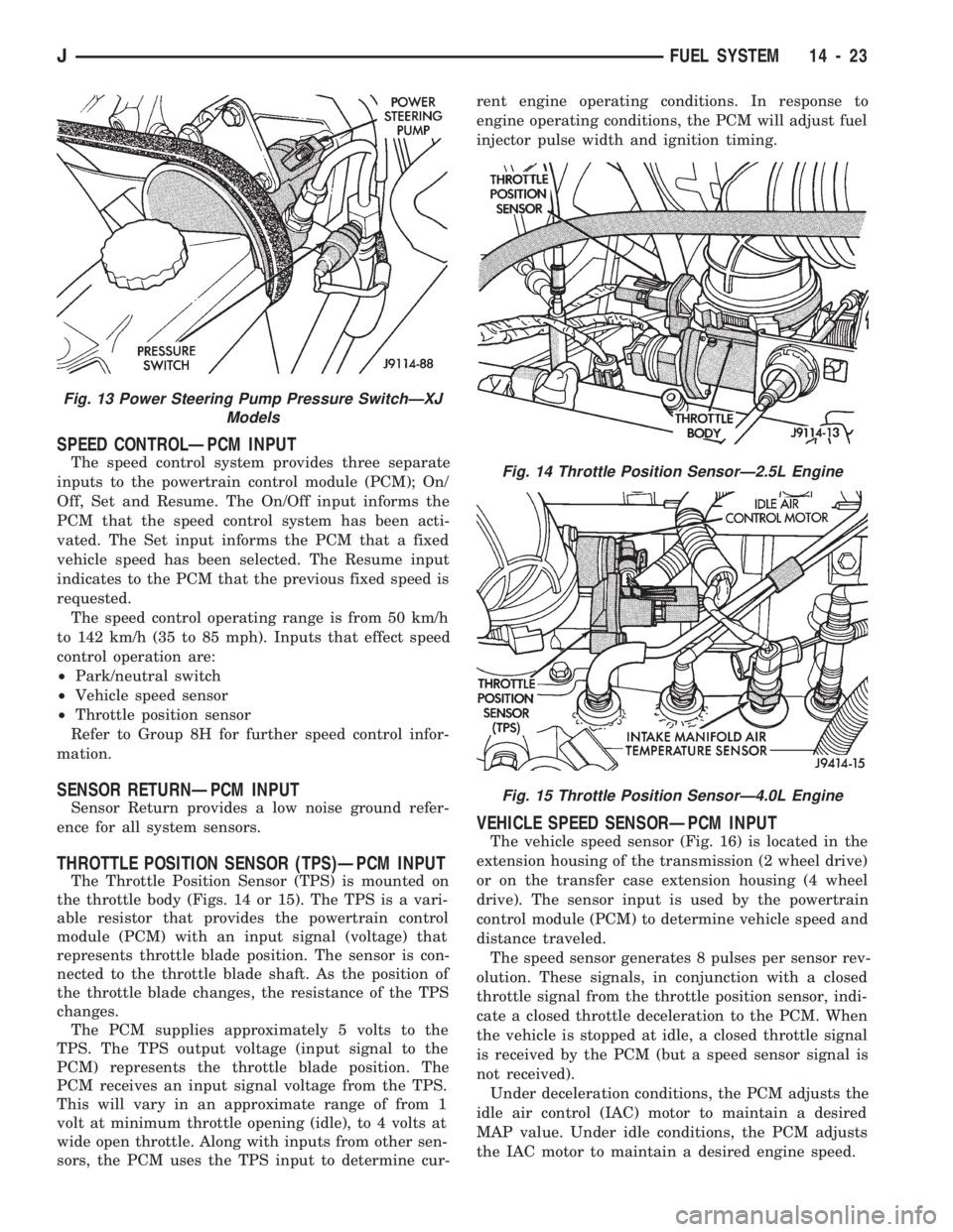
The Throttle Position Sensor (TPS) is mounted on
the throttle body (Figs. 14 or 15). The TPS is a vari-
able resistor that provides the powertrain control
module (PCM) with an input signal (voltage) that
represents throttle blade position. The sensor is con-
nected to the throttle blade shaft. As the position of
the throttle blade changes, the resistance of the TPS
changes.
The PCM supplies approximately 5 volts to the
TPS. The TPS output voltage (input signal to the
PCM) represents the throttle blade position. The
PCM receives an input signal voltage from the TPS.
This will vary in an approximate range of from 1
volt at minimum throttle opening (idle), to 4 volts at
wide open throttle. Along with inputs from other sen-
sors, the PCM uses the TPS input to determine cur-rent engine operating conditions. In response to
engine operating conditions, the PCM will adjust fuel
injector pulse width and ignition timing.
VEHICLE SPEED SENSORÐPCM INPUT
The vehicle speed sensor (Fig. 16) is located in the
extension housing of the transmission (2 wheel drive)
or on the transfer case extension housing (4 wheel
drive). The sensor input is used by the powertrain
control module (PCM) to determine vehicle speed and
distance traveled.
The speed sensor generates 8 pulses per sensor rev-
olution. These signals, in conjunction with a closed
throttle signal from the throttle position sensor, indi-
cate a closed throttle deceleration to the PCM. When
the vehicle is stopped at idle, a closed throttle signal
is received by the PCM (but a speed sensor signal is
not received).
Under deceleration conditions, the PCM adjusts the
idle air control (IAC) motor to maintain a desired
MAP value. Under idle conditions, the PCM adjusts
the IAC motor to maintain a desired engine speed.
Fig. 13 Power Steering Pump Pressure SwitchÐXJ
Models
Fig. 14 Throttle Position SensorÐ2.5L Engine
Fig. 15 Throttle Position SensorÐ4.0L Engine
JFUEL SYSTEM 14 - 23
Page 150 of 1784
ABS BRAKE DIAGNOSIS
INDEX
page page
ABS Fault Diagnosis....................... 4
ABS System Wiring and Electrical Circuits...... 4
ABS Warning Light Display.................. 3
Brake Warning Light Display................. 4
Diagnosis Procedures...................... 3
ECU Diagnosis........................... 4
HCU Diagnosis........................... 4Loss of Sensor Input....................... 3
Operating Sound Levels.................... 3
Rear Speed Sensor Air Gap................. 3
Steering Response........................ 3
Vehicle Response in Antilock Mode............ 3
Wheel/Tire Size and Input Signals............. 3
DIAGNOSIS PROCEDURES
ABS diagnosis involves three basic steps. First is
observation of the warning light display. Second is a
visual examination for low fluid level, leaks, parking
brakes applied, or obvious damage to system compo-
nents or wires. The third step involves using the
DRB II scan tool to identify a faulty component.
The visual examination requires a check of reser-
voir fluid level and all system components. Things to
look for are leaks, loose connections, or obvious com-
ponent damage.
The final diagnosis step involves using the DRB II
scan tool to determine the specific circuit or compo-
nent at fault. The tester is connected to the ABS di-
agnostic connector in the passenger compartment.
The connector is at the driver side of the center con-
sole under the instrument panel. Refer to the DRB II
scan tool Manual for tester procedures. Also refer to
the ABS Fault Diagnosis charts at the end of this
section for additional diagnosis information.
Initial faults should be cleared and the vehicle road
tested to reset any faults that remain in the system.
Faults can be cleared with the DRB II scan tool.
REAR SPEED SENSOR AIR GAP
The front wheel sensors are fixed and cannot be ad-
justed. Only the rear sensor air gap is adjustable. Air
gap must be set with a brass feeler gauge.
Correct air gap is important to proper signal gen-
eration. An air gap that is too large may cause com-
plete loss of sensor input. Or, a gap that is too small
could produce a false input signal, or damaging con-
tact between the sensor and tone ring.
WHEEL/TIRE SIZE AND INPUT SIGNALS
Antilock system operation is dependant on accurate
signals from the wheel speed sensors. Ideally, the ve-
hicle wheels and tires should all be the same size
and type. However, the Jeep ABS system is designed
to function with a compact spare tire installed.
OPERATING SOUND LEVELS
The ABS pump and solenoid valves may produce
some sound as they cycle on and off. This is a normal
condition and should not be mistaken for faulty oper-
ation.
VEHICLE RESPONSE IN ANTILOCK MODE
During antilock braking, the HCU solenoid valves
cycle rapidly in response to ECU inputs.
The driver will experience a pulsing sensation
within the vehicle as the solenoids decrease, hold, or
increase pressure as needed. A pulsing brake pedal
will also be noted.
The pulsing sensation occurs as the solenoids cycle
during antilock mode braking. A slight pulse in the
brake pedal may also be noted during the dynamic
self check part of system initialization.
STEERING RESPONSE
A modest amount of steering input is required dur-
ing extremely high deceleration braking, or when
braking on differing traction surfaces. An example of
differing traction surfaces would be when the left
side wheels are on ice and the right side wheels are
on dry pavement.
LOSS OF SENSOR INPUT
Sensor malfunctions will most likely be due to
loose connections, damaged sensor wires, incorrect
rear sensor air gap, or a malfunctioning sensor. Ad-
ditional causes of sensor faults would be sensor and
tone ring misalignment or damage.
ABS WARNING LIGHT DISPLAY
ABS Light Illuminates At Startup
The amber ABS light illuminates at startup as
part of the system self check feature. The light illu-
minates for 2-3 seconds then goes off as part of the
normal self check routine.
ABS Light Remains On After Startup
An ABS system fault is indicated when the light
remains on after startup. Diagnosis with the DRB II
JBRAKES 5 - 3
Page 154 of 1784
SERVICE BRAKE DIAGNOSIS
INDEX
page page
Component Inspection...................... 8
Diagnosing Parking Brake Problems.......... 10
Diagnosing Service Brake Problems........... 8
Diagnosis Procedures...................... 7
General Information........................ 7Master Cylinder/Power Booster Test.......... 11
Power Booster Check Valve Test............ 11
Power Booster Vacuum Test................ 12
Preliminary Brake Check.................... 7
Road Testing............................ 7
GENERAL INFORMATION
The diagnosis information in this section covers
service brake components which include:
²disc brake calipers
²disc brakeshoes
²drum brake wheel cylinders
²drum brakeshoes and brake drums
²drum brake support plates
²parking brake mechanism
²master cylinder/combination valve
²vacuum power brake booster
²brake pedal and brakelight switch
²brake warning light
DIAGNOSIS PROCEDURES
Service brake diagnosis involves determining if a
problem is related to a mechanical, hydraulic or vac-
uum operated component. A preliminary brake
check, followed by road testing and component in-
spection are needed to determine a problem cause.
Road testing will either verify proper brake opera-
tion or confirm the existence of a problem. Compo-
nent inspection will, in most cases, identify the
actual part responsible for a problem.
The first diagnosis step is the preliminary brake
check. This involves inspecting fluid level, parking
brake action, wheel and tire condition, checking for
obvious leaks or component damage and testing
brake pedal response. A road test will confirm or
deny the existence of a problem. The final diagnosis
procedure involves road test analysis and a visual in-
spection of brake components.
PRELIMINARY BRAKE CHECK
(1) If amber antilock light is illuminated, refer to
Antilock Brake System Diagnosis. However, if red
warning light is illuminated, or if neither warning
light is illuminated, continue with diagnosis.
(2) Check condition of tires and wheels. Damaged
wheels and worn, damaged, or underinflated tires
can cause pull, shudder, tramp and a condition simi-
lar to grab.
(3) If complaint was based on noise when braking,
check suspension components. Jounce front and rearof vehicle and listen for noise that might be caused
by loose, worn, or damaged suspension or steering
components.
(4) Inspect brake fluid level:
(a) If vehicle has one-piece master cylinder, fluid
level should be to 6 mm (1/4 in.) of reservoir rim. If
vehicle two-piece, removable reservoir, correct level
is to top of indicator rings in reservoir.
(b) On models with ABS brakes, preferred level
is to MAX mark on reservoir. Acceptable level is
between MAX and MIN marks.
(c) Remember that fluid level in the front and
rear reservoir compartments will decrease in pro-
portion to normal lining wear. However, if fluid
level is abnormally low, look for leaks at calipers,
wheel cylinders, brakelines and master cylinder.
(5) Inspect brake fluid condition:
(a) Fluid should be reasonably clear and free of
foreign material.Note that brake fluid tends to
darken over time. This is normal and should
not be mistaken for contamination. If fluid is
clear of foreign material, it is OK.
(b) If fluid is highly discolored, or appears to con-
tain foreign material, drain out a sample with a
clean suction gun. Pour sample in a glass container
and note condition.
(c) If fluid separates into layers, obviously con-
tains oil, or a substance other than brake fluid,
system seals and cups will have to be replaced and
hydraulic system flushed.
(6) Check parking brake operation. Verify free
movement and full release of cables and foot pedal or
hand lever. Also note if vehicle was being operated
with parking brake partially applied.
(7) Check brake pedal operation. Verify that pedal
does not bind and has adequate free play. If pedal
lacks free play, check pedal and power booster for be-
ing loose or for bind condition. Do not road test until
condition is corrected.
(8) If components inspected look OK, road test the
vehicle.
ROAD TESTING
(1) If amber warning light is illuminated, problem
is with antilock system component. Refer to Antilock
Brake System Diagnosis.
JBRAKES 5 - 7
Page 157 of 1784

when the cover is off. The second involves adding to,
or filling the cylinder reservoirs with a non-recom-
mended fluid.
Brake fluid contaminated with only dirt, or debris
usually retains a normal appearance. In some cases,
the foreign material will remain suspended in the
fluid and be visible. The fluid and foreign material
can be removed from the reservoir with a suction
gun but only if the brakes have not been applied. If
the brakes are applied after contamination, system
flushing will be required. The master cylinder may
also have to be disassembled, cleaned and the piston
seals replaced. Foreign material lodged in the reser-
voir compensator/return ports can cause brake drag
by restricting fluid return after brake application.
Brake fluid contaminated by a non-recommended
fluid will usually be discolored, milky, oily looking,
or foamy. In some cases, it may even appear as if the
fluid contains sludge.However, remember that
brake fluid will darken in time and occasionally
be cloudy in appearance. These are normal con-
ditions and should not be mistaken for contami-
nation.
If some type of oil has been added to the system,
the fluid will separate into distinct layers. To verify
this, drain off a sample with a clean suction gun.
Then pour the sample into a glass container and ob-
serve fluid action. If the fluid separates into distinct
layers, it is definitely contaminated.
The only real correction for contamination by non-
recommended fluid is to flush the entire hydraulic
system and replace all the seals.
BRAKE NOISE
Squeak/Squeal
Brake squeak or squeal may be due to linings that
are wet or contaminated with brake fluid, grease, or
oil. Glazed linings and rotors with hard spots can
also contribute to squeak. Dirt and foreign material
embedded in the brake lining will also cause squeak/
squeal.
A very loud squeak or squeal is frequently a sign
of severely worn brake lining. If the lining has worn
through to the brakeshoes in spots, metal-to-metal
contact occurs. If the condition is allowed to continue,
rotors can become so scored that replacement is nec-
essary.
Thump/Clunk
Thumping or clunk noises during braking are fre-
quentlynotcaused by brake components. In many
cases, such noises are caused by loose or damaged
steering, suspension, or engine components. How-
ever, calipers that bind on the slide surfaces can gen-
erate a thump or clunk noise. In addition, worn out,
improperly adjusted, or improperly assembled rear
brakeshoes can also produce a thump noise.Chatter/Shudder
Brake chatter, or shudder is usually caused by
loose or worn components, or glazed/burnt lining. Ro-
tors with hard spots can also contribute to chatter.
Additional causes of chatter are out of tolerance ro-
tors, brake lining not securely attached to the shoes,
loose wheel bearings and contaminated brake lining.
BRAKELINING CONTAMINATION
Brakelining contamination is usually a product of
leaking calipers or wheel cylinders, driving through
deep water puddles, or lining that has become cov-
ered with grease and grit during repair.
WHEEL AND TIRE PROBLEMS
Some conditions attributed to brake components
may actually be caused by a wheel or tire problem.
A damaged wheel can cause shudder, vibration and
pull. A worn or damaged tire can also cause pull.
Severely worn tires with very little tread left can
produce a condition similar to grab as the tire loses
and recovers traction.
Flat-spotted tires can cause vibration and wheel
tramp and generate shudder during brake operation.
A tire with internal damage such as a severe
bruise or ply separation can cause pull and vibration.
DIAGNOSING PARKING BRAKE PROBLEMS
Adjustment Mechanism
Parking brake adjustment is controlled by a
cable tensioner mechanism. This applies to 1991
through 1994 YJ models and 1992 and later XJ
models. The cable tensioner, once adjusted at
the factory, will not need further adjustment un-
der normal circumstances. There are only two
instances when adjustment is required. The first
is when a new tensioner, or cables have been in-
stalled. And the second, is when the tensioner
and cables are disconnected for access to other
brake components.
Parking Brake problem Causes
In most cases, the actual cause of an improperly
functioning parking brake (too loose/too tight/wont
hold), can be traced to a drum brake component.
The leading cause of improper parking brake
operation, is excessive clearance between the
brakeshoes and the drum surface. Excessive
clearance is a result of: lining and/or drum wear;
oversize drums; or inoperative shoe adjuster
components.
Excessive parking brake lever travel (sometimes
described as a loose lever or too loose condition), is
the result of worn brakeshoes/drums, improper
brakeshoe adjustment, or mis-assembled brake parts.
A ``too loose'' condition can also be caused by inop-
erative brakeshoe adjusters. If the adjusters are mis-
5 - 10 BRAKESJ
Page 171 of 1784
DISC BRAKES
INDEX
page page
Caliper Assembly........................ 29
Caliper Cleaning and Inspection............. 28
Caliper Disassembly...................... 27
Caliper Installation........................ 30
Caliper Operation and Wear Compensation..... 24
Caliper Removal......................... 27
Disc Brake Rotor Refinishing................ 32
Disc Brake Rotor Runout................... 31Disc Brake Rotor Thickness................ 31
Disc Brake Rotor Thickness Variation......... 31
Disc Brakeshoe Installation................. 26
Disc Brakeshoe Removal.................. 25
General Information....................... 24
Rotor Installation......................... 30
Rotor Removal.......................... 30
Wheel Nut Tightening..................... 32
GENERAL INFORMATION
1994 Jeep XJ/YJ models are equipped with single
piston, floating-type disc brake calipers. Ventilated,
cast rotors are used for all applications.
The disc brake calipers are supported in mounting
arms that are an integral part of the steering
knuckle. The calipers slide on mounting bolts that
also attach the calipers to the steering knuckle.
CALIPER OPERATION AND WEAR COMPENSATION
Caliper Operation
The significant feature of single piston caliper op-
eration is that the calipers are free to slide laterally
on the mounting bolts. It is the freedom of lateral
movement that allows continous compensation for
lining wear.
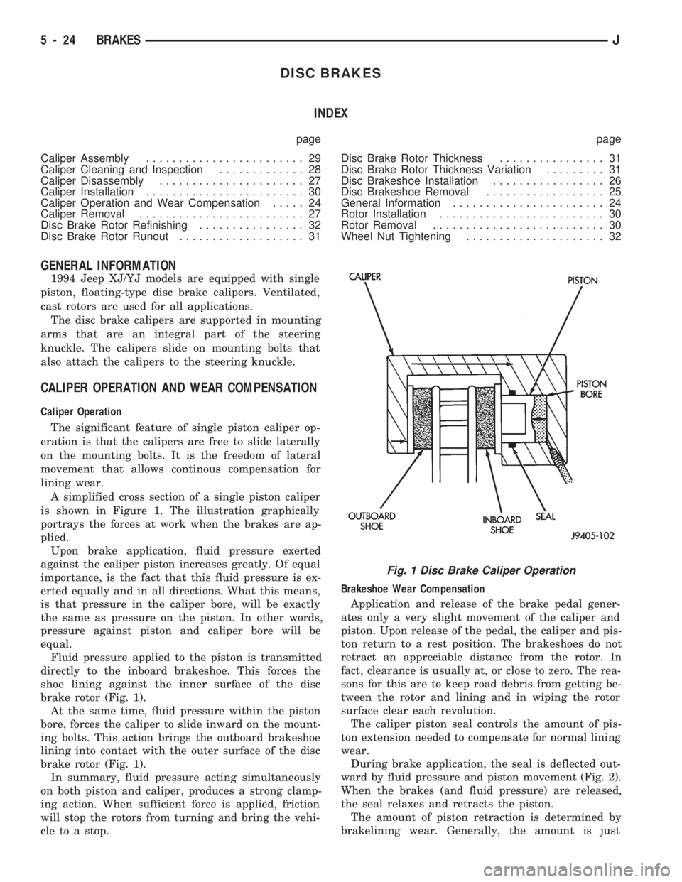
A simplified cross section of a single piston caliper
is shown in Figure 1. The illustration graphically
portrays the forces at work when the brakes are ap-
plied.
Upon brake application, fluid pressure exerted
against the caliper piston increases greatly. Of equal
importance, is the fact that this fluid pressure is ex-
erted equally and in all directions. What this means,
is that pressure in the caliper bore, will be exactly
the same as pressure on the piston. In other words,
pressure against piston and caliper bore will be
equal.
Fluid pressure applied to the piston is transmitted
directly to the inboard brakeshoe. This forces the
shoe lining against the inner surface of the disc
brake rotor (Fig. 1).
At the same time, fluid pressure within the piston
bore, forces the caliper to slide inward on the mount-
ing bolts. This action brings the outboard brakeshoe
lining into contact with the outer surface of the disc
brake rotor (Fig. 1).
In summary, fluid pressure acting simultaneously
on both piston and caliper, produces a strong clamp-
ing action. When sufficient force is applied, friction
will stop the rotors from turning and bring the vehi-
cle to a stop.Brakeshoe Wear Compensation
Application and release of the brake pedal gener-
ates only a very slight movement of the caliper and
piston. Upon release of the pedal, the caliper and pis-
ton return to a rest position. The brakeshoes do not
retract an appreciable distance from the rotor. In
fact, clearance is usually at, or close to zero. The rea-
sons for this are to keep road debris from getting be-
tween the rotor and lining and in wiping the rotor
surface clear each revolution.
The caliper piston seal controls the amount of pis-
ton extension needed to compensate for normal lining
wear.
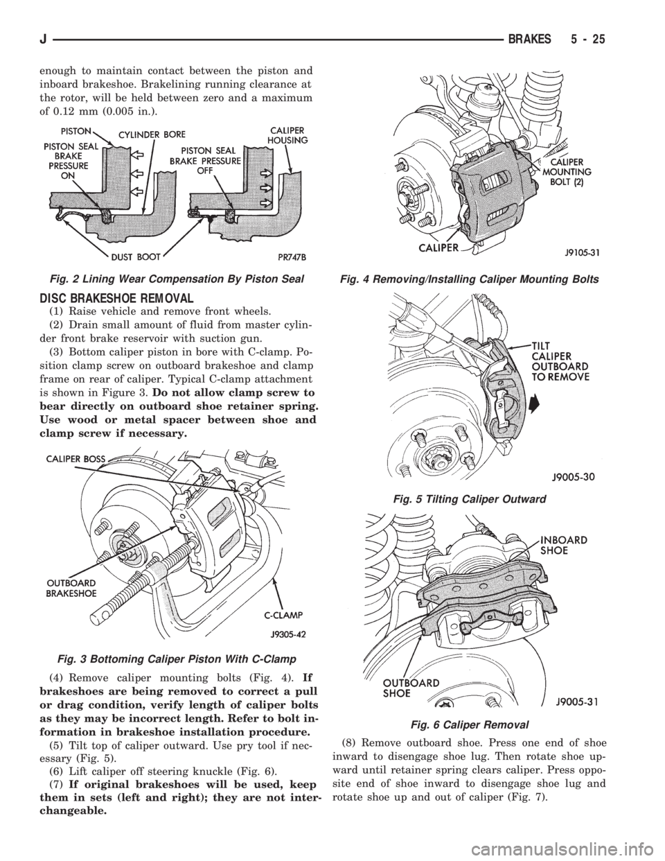
During brake application, the seal is deflected out-
ward by fluid pressure and piston movement (Fig. 2).
When the brakes (and fluid pressure) are released,
the seal relaxes and retracts the piston.
The amount of piston retraction is determined by
brakelining wear. Generally, the amount is just
Fig. 1 Disc Brake Caliper Operation
5 - 24 BRAKESJ
Page 172 of 1784
enough to maintain contact between the piston and
inboard brakeshoe. Brakelining running clearance at
the rotor, will be held between zero and a maximum
of 0.12 mm (0.005 in.).
DISC BRAKESHOE REMOVAL
(1) Raise vehicle and remove front wheels.
(2) Drain small amount of fluid from master cylin-
der front brake reservoir with suction gun.
(3) Bottom caliper piston in bore with C-clamp. Po-
sition clamp screw on outboard brakeshoe and clamp
frame on rear of caliper. Typical C-clamp attachment
is shown in Figure 3.Do not allow clamp screw to
bear directly on outboard shoe retainer spring.
Use wood or metal spacer between shoe and
clamp screw if necessary.
(4) Remove caliper mounting bolts (Fig. 4).If
brakeshoes are being removed to correct a pull
or drag condition, verify length of caliper bolts
as they may be incorrect length. Refer to bolt in-
formation in brakeshoe installation procedure.
(5) Tilt top of caliper outward. Use pry tool if nec-
essary (Fig. 5).
(6) Lift caliper off steering knuckle (Fig. 6).
(7)If original brakeshoes will be used, keep
them in sets (left and right); they are not inter-
changeable.(8) Remove outboard shoe. Press one end of shoe
inward to disengage shoe lug. Then rotate shoe up-
ward until retainer spring clears caliper. Press oppo-
site end of shoe inward to disengage shoe lug and
rotate shoe up and out of caliper (Fig. 7).
Fig. 2 Lining Wear Compensation By Piston Seal
Fig. 3 Bottoming Caliper Piston With C-Clamp
Fig. 4 Removing/Installing Caliper Mounting Bolts
Fig. 5 Tilting Caliper Outward
Fig. 6 Caliper Removal
JBRAKES 5 - 25
Page 177 of 1784
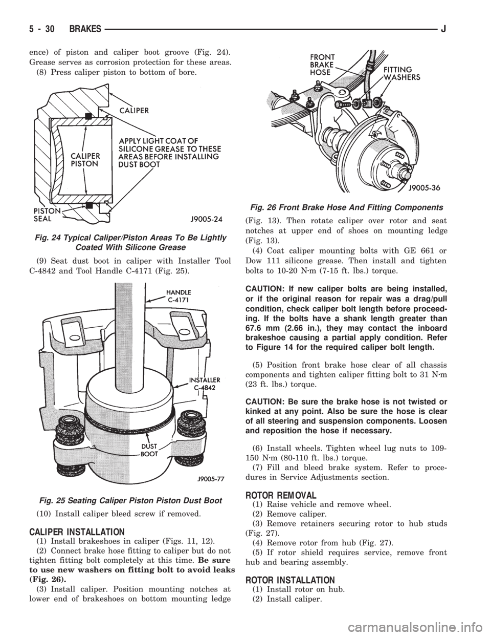
ence) of piston and caliper boot groove (Fig. 24).
Grease serves as corrosion protection for these areas.
(8) Press caliper piston to bottom of bore.
(9) Seat dust boot in caliper with Installer Tool
C-4842 and Tool Handle C-4171 (Fig. 25).
(10) Install caliper bleed screw if removed.
CALIPER INSTALLATION
(1) Install brakeshoes in caliper (Figs. 11, 12).
(2) Connect brake hose fitting to caliper but do not
tighten fitting bolt completely at this time.Be sure
to use new washers on fitting bolt to avoid leaks
(Fig. 26).
(3) Install caliper. Position mounting notches at
lower end of brakeshoes on bottom mounting ledge(Fig. 13). Then rotate caliper over rotor and seat
notches at upper end of shoes on mounting ledge
(Fig. 13).
(4) Coat caliper mounting bolts with GE 661 or
Dow 111 silicone grease. Then install and tighten
bolts to 10-20 Nzm (7-15 ft. lbs.) torque.
CAUTION: If new caliper bolts are being installed,
or if the original reason for repair was a drag/pull
condition, check caliper bolt length before proceed-
ing. If the bolts have a shank length greater than
67.6 mm (2.66 in.), they may contact the inboard
brakeshoe causing a partial apply condition. Refer
to Figure 14 for the required caliper bolt length.
(5) Position front brake hose clear of all chassis
components and tighten caliper fitting bolt to 31 Nzm
(23 ft. lbs.) torque.
CAUTION: Be sure the brake hose is not twisted or
kinked at any point. Also be sure the hose is clear
of all steering and suspension components. Loosen
and reposition the hose if necessary.
(6) Install wheels. Tighten wheel lug nuts to 109-
150 Nzm (80-110 ft. lbs.) torque.
(7) Fill and bleed brake system. Refer to proce-
dures in Service Adjustments section.
ROTOR REMOVAL
(1) Raise vehicle and remove wheel.
(2) Remove caliper.
(3) Remove retainers securing rotor to hub studs
(Fig. 27).
(4) Remove rotor from hub (Fig. 27).
(5) If rotor shield requires service, remove front
hub and bearing assembly.
ROTOR INSTALLATION
(1) Install rotor on hub.
(2) Install caliper.
Fig. 24 Typical Caliper/Piston Areas To Be Lightly
Coated With Silicone Grease
Fig. 25 Seating Caliper Piston Piston Dust Boot
Fig. 26 Front Brake Hose And Fitting Components
5 - 30 BRAKESJ