1994 JEEP CHEROKEE fold seats
[x] Cancel search: fold seatsPage 903 of 1784
(9) Install the intake and engine exhaust mani-
folds (refer to Group 11, Exhaust System and Intake
Manifold for the proper procedures).
(10) Install the fuel lines and the vacuum advance
hose.
(11) If equipped, attach the power steering pump
and bracket.
(12) Install the push rods, rocker arms, pivots and
bridges in the order they were removed.
(13) Install the engine cylinder head cover.
(14) Attach the air conditioner compressor mount-
ing bracket to the engine cylinder head and block.
Tighten the bolts to 40 Nzm (30 ft. lbs.) torque.
(15) Attach the air conditioning compressor to the
bracket. Tighten the bolts to 27 Nzm (20 ft. lbs.)
torque.
CAUTION: The serpentine drive belt must be routed
correctly. Incorrect routing can cause the water
pump to turn in the opposite direction causing the
engine to overheat.
(16) Install the serpentine drive belt and correctly
tension the belt (refer to Group 7, Cooling System for
the proper procedure).
(17) Install the air cleaner and ducting.
(18) Install the engine cylinder head cover.
(19) Connect the hoses to the engine thermostat
housing and fill the cooling system to the specified
level (refer to Group 7, Cooling Systems for the
proper procedure).
(20) The automatic transmission throttle linkage
and cable must be adjusted after completing the en-
gine cylinder head installation (refer to Group 21,
Transmissions for the proper procedures).
(21) Install the temperature sending unit and con-
nect the wire connector.
(22) Connect the fuel pipe and vacuum advance
hose.
(23) Connect negative cable to battery.
(24) Connect the upper radiator hose and heater
hose at the engine thermostat housing.
(25) Fill the cooling system. Check for leaks.WARNING: USE EXTREME CAUTION WHEN THE
ENGINE IS OPERATING. DO NOT STAND IN DIRECT
LINE WITH THE FAN. DO NOT PUT HANDS NEAR
THE PULLEYS, BELTS OR FAN. DO NOT WEAR
LOOSE CLOTHING.
(26) Operate the engine with the radiator cap off.
Inspect for leaks and continue operating the engine
until the engine thermostat opens. Add coolant, if re-
quired.
VALVE SPRINGS AND OIL SEALS
This procedure can be done with the engine cylin-
der head installed on the block.
REMOVAL
Each valve spring is held in place by a retainer
and a set of conical valve locks. The locks can be re-
moved only by compressing the valve spring.
(1) Remove the engine cylinder head cover.
(2) Remove capscrews, bridge and pivot assemblies
and rocker arms for access to each valve spring to be
removed.
(3) Remove push rods. Retain the push rods,
bridges, pivots and rocker arms in the same order
and position as removed.
(4) Inspect the springs and retainer for cracks and
possible signs of weakening.
(5) Remove the spark plug(s) adjacent to the cylin-
der(s) below the valve springs to be removed.
(6) Install a 14 mm (1/2 inch) (thread size) air hose
adaptor in the spark plug hole. An adaptor can be
constructed by welding an air hose connection to the
body of a spark plug with the porcelain removed.
(7) Connect an air hose to the adapter and apply
air pressure slowly. Maintain at least 621 kPa (90
psi) of air pressure in the cylinder to hold the valves
against their seats. For vehicles equipped with an air
conditioner, use a flexible air adaptor when servicing
the No.1 cylinder.
(8) Tap the retainer or tip with a rawhide hammer
to loosen the lock from the retainer. Use Valve
Spring Compressor Tool MD-998772A to compress
the spring and remove the locks (Fig. 5).
(9) Remove valve spring and retainer (Fig. 5).
(10) Remove valve stem oil seals (Fig. 5). Note the
valve seals are different for intake and exhaust
valves. The top of each seal is marked either INT
(Intake) or EXH (Exhaust). DO NOT mix the seals.
INSPECTION
Inspect the valve stems, especially the grooves. An
Arkansas smooth stone should be used to remove
nicks and high spots.
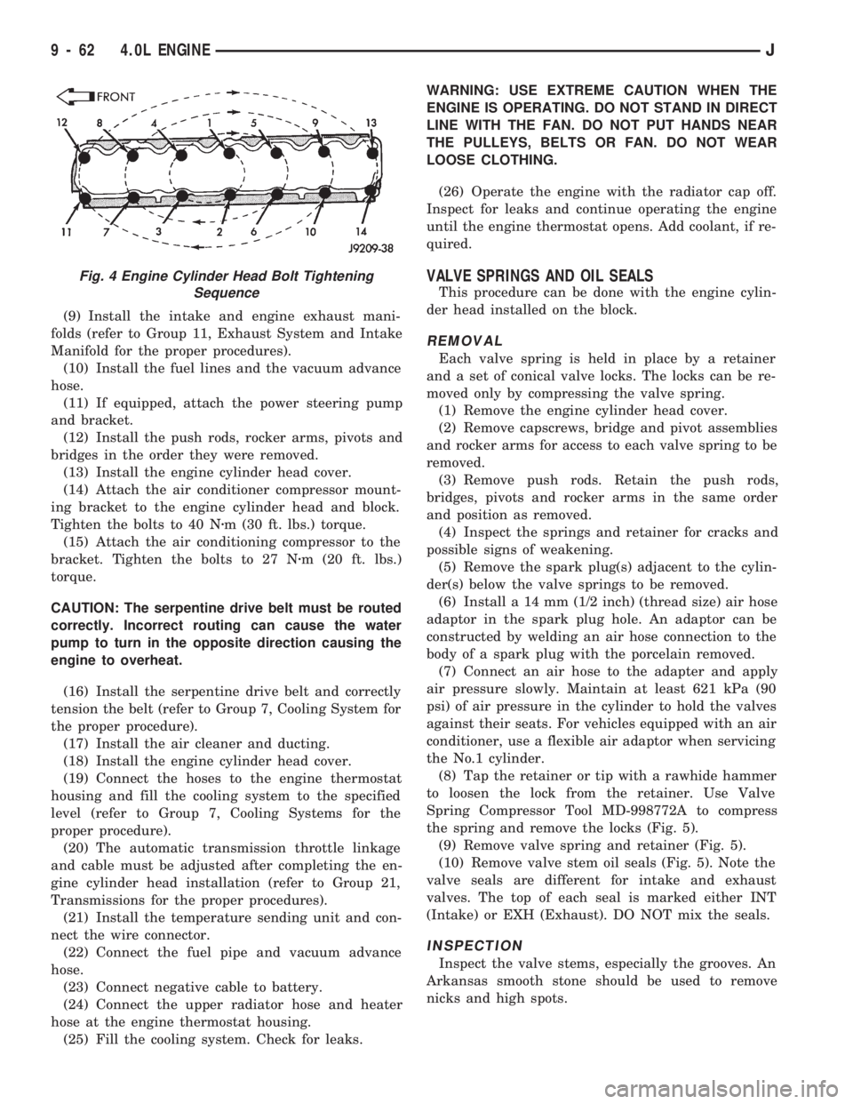
Fig. 4 Engine Cylinder Head Bolt Tightening
Sequence
9 - 62 4.0L ENGINEJ
Page 1557 of 1784
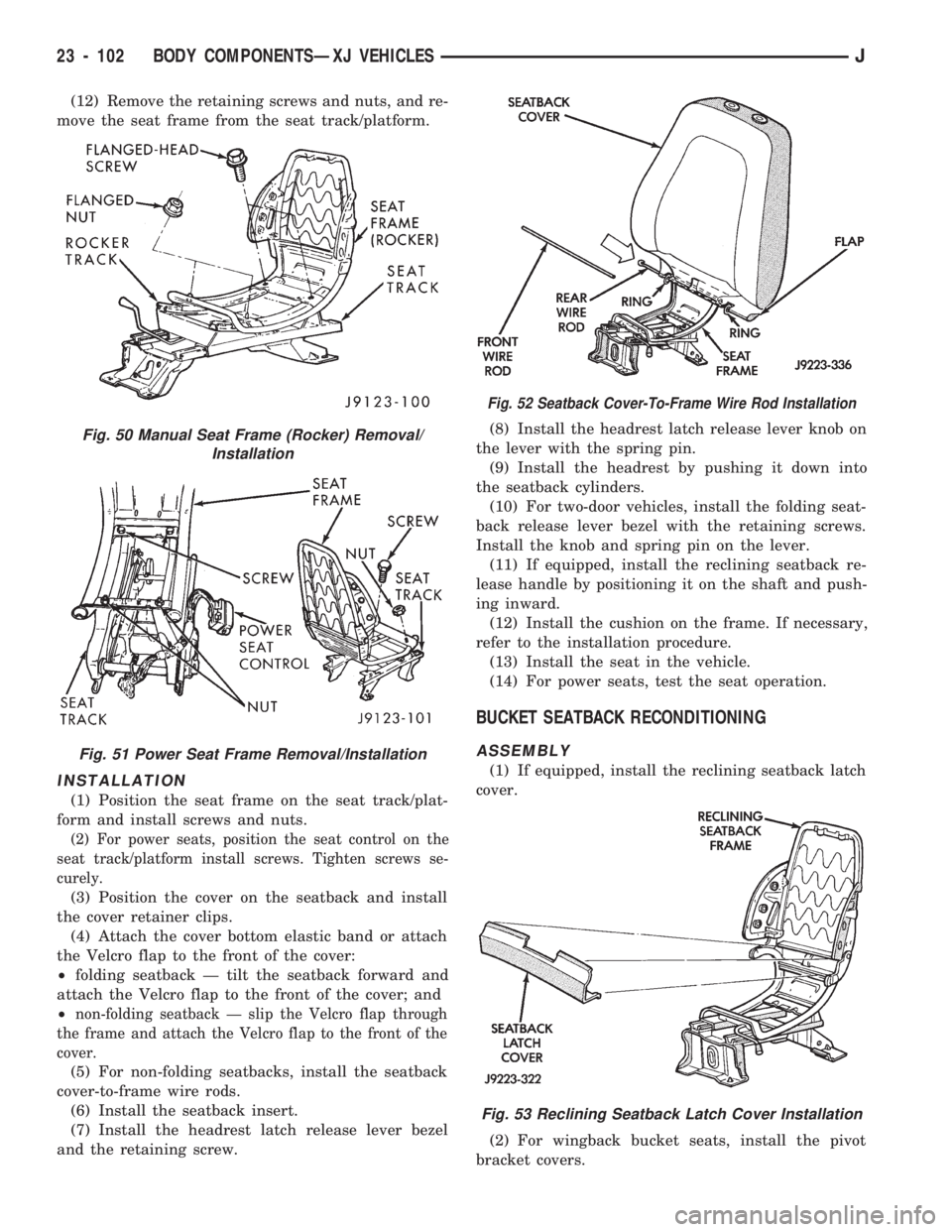
(12) Remove the retaining screws and nuts, and re-
move the seat frame from the seat track/platform.
INSTALLATION
(1) Position the seat frame on the seat track/plat-
form and install screws and nuts.
(2) For power seats, position the seat control on the
seat track/platform install screws. Tighten screws se-
curely.
(3) Position the cover on the seatback and install
the cover retainer clips.
(4) Attach the cover bottom elastic band or attach
the Velcro flap to the front of the cover:
²folding seatback Ð tilt the seatback forward and
attach the Velcro flap to the front of the cover; and
²
non-folding seatback Ð slip the Velcro flap through
the frame and attach the Velcro flap to the front of the
cover.
(5) For non-folding seatbacks, install the seatback
cover-to-frame wire rods.
(6) Install the seatback insert.
(7) Install the headrest latch release lever bezel
and the retaining screw.(8) Install the headrest latch release lever knob on
the lever with the spring pin.
(9) Install the headrest by pushing it down into
the seatback cylinders.
(10) For two-door vehicles, install the folding seat-
back release lever bezel with the retaining screws.
Install the knob and spring pin on the lever.
(11) If equipped, install the reclining seatback re-
lease handle by positioning it on the shaft and push-
ing inward.
(12) Install the cushion on the frame. If necessary,
refer to the installation procedure.
(13) Install the seat in the vehicle.
(14) For power seats, test the seat operation.
BUCKET SEATBACK RECONDITIONING
ASSEMBLY
(1) If equipped, install the reclining seatback latch
cover.
(2) For wingback bucket seats, install the pivot
bracket covers.
Fig. 50 Manual Seat Frame (Rocker) Removal/
Installation
Fig. 51 Power Seat Frame Removal/Installation
Fig. 52 Seatback Cover-To-Frame Wire Rod Installation
Fig. 53 Reclining Seatback Latch Cover Installation
23 - 102 BODY COMPONENTSÐXJ VEHICLESJ
Page 1558 of 1784
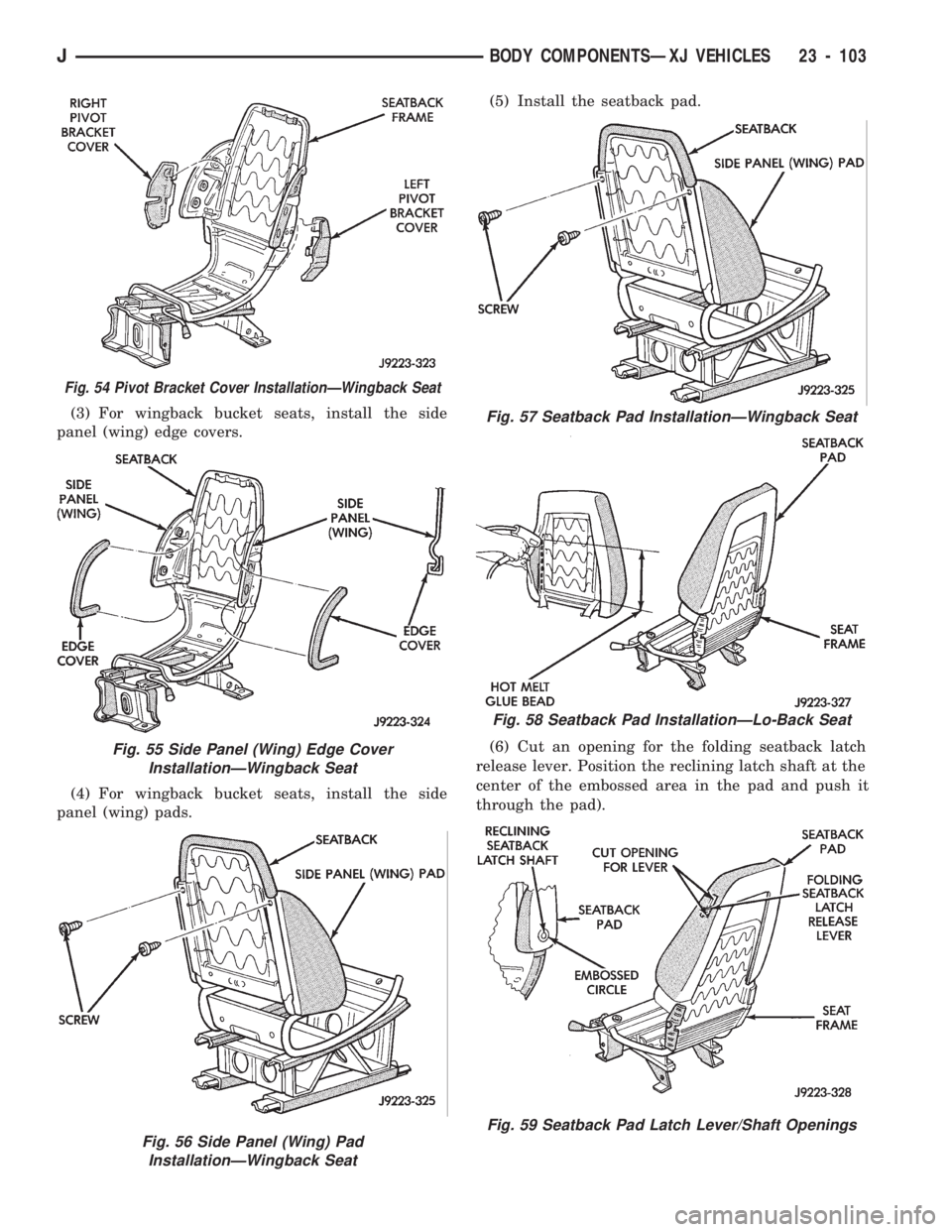
(3) For wingback bucket seats, install the side
panel (wing) edge covers.
(4) For wingback bucket seats, install the side
panel (wing) pads.(5) Install the seatback pad.
(6) Cut an opening for the folding seatback latch
release lever. Position the reclining latch shaft at the
center of the embossed area in the pad and push it
through the pad).
Fig. 56 Side Panel (Wing) Pad
InstallationÐWingback Seat
Fig. 54 Pivot Bracket Cover InstallationÐWingback Seat
Fig. 55 Side Panel (Wing) Edge Cover
InstallationÐWingback Seat
Fig. 57 Seatback Pad InstallationÐWingback Seat
Fig. 58 Seatback Pad InstallationÐLo-Back Seat
Fig. 59 Seatback Pad Latch Lever/Shaft Openings
JBODY COMPONENTSÐXJ VEHICLES 23 - 103
Page 1560 of 1784
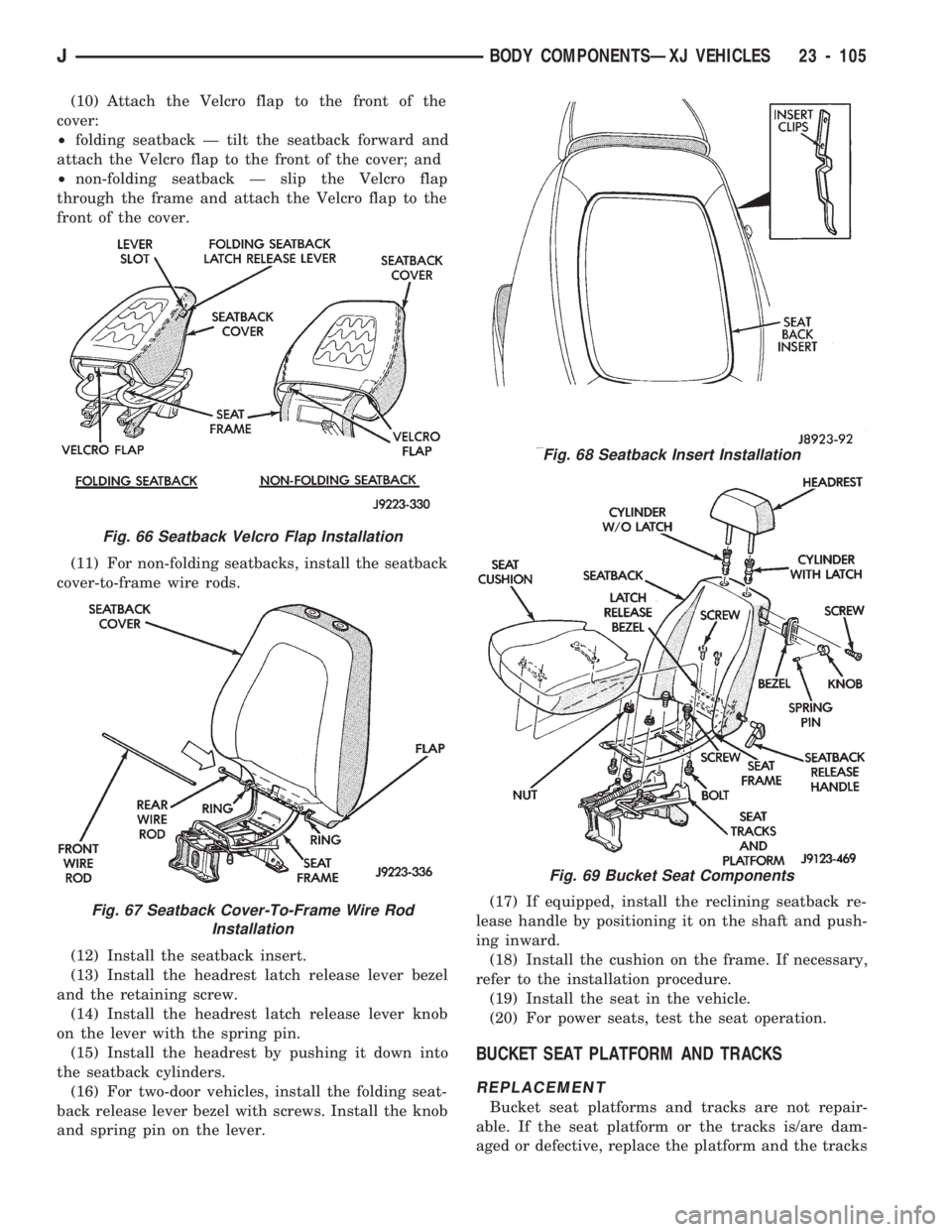
(10) Attach the Velcro flap to the front of the
cover:
²folding seatback Ð tilt the seatback forward and
attach the Velcro flap to the front of the cover; and
²non-folding seatback Ð slip the Velcro flap
through the frame and attach the Velcro flap to the
front of the cover.
(11) For non-folding seatbacks, install the seatback
cover-to-frame wire rods.
(12) Install the seatback insert.
(13) Install the headrest latch release lever bezel
and the retaining screw.
(14) Install the headrest latch release lever knob
on the lever with the spring pin.
(15) Install the headrest by pushing it down into
the seatback cylinders.
(16) For two-door vehicles, install the folding seat-
back release lever bezel with screws. Install the knob
and spring pin on the lever.(17) If equipped, install the reclining seatback re-
lease handle by positioning it on the shaft and push-
ing inward.
(18) Install the cushion on the frame. If necessary,
refer to the installation procedure.
(19) Install the seat in the vehicle.
(20) For power seats, test the seat operation.
BUCKET SEAT PLATFORM AND TRACKS
REPLACEMENT
Bucket seat platforms and tracks are not repair-
able. If the seat platform or the tracks is/are dam-
aged or defective, replace the platform and the tracks
Fig. 66 Seatback Velcro Flap Installation
Fig. 67 Seatback Cover-To-Frame Wire Rod
Installation
Fig. 68 Seatback Insert Installation
Fig. 69 Bucket Seat Components
JBODY COMPONENTSÐXJ VEHICLES 23 - 105
Page 1561 of 1784
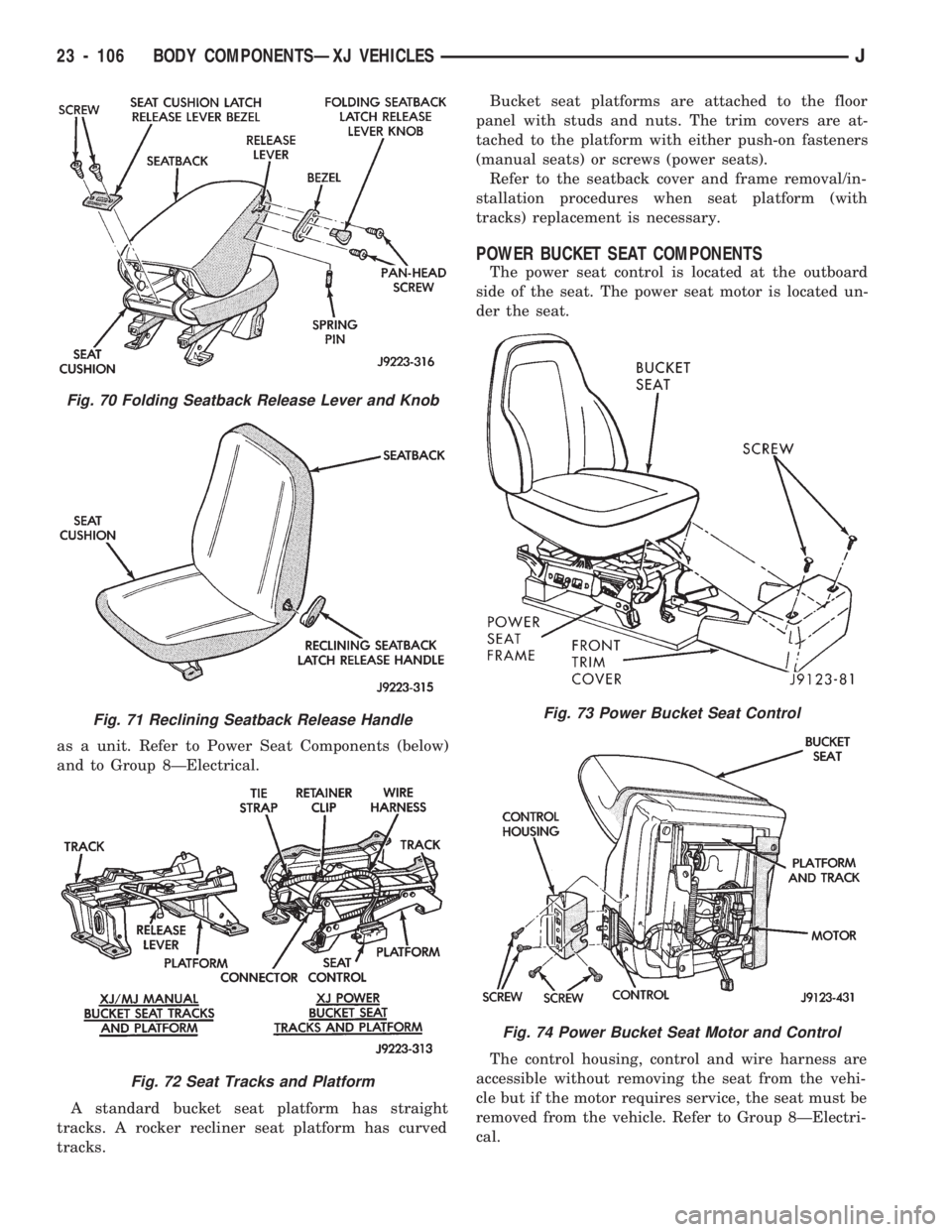
as a unit. Refer to Power Seat Components (below)
and to Group 8ÐElectrical.
A standard bucket seat platform has straight
tracks. A rocker recliner seat platform has curved
tracks.Bucket seat platforms are attached to the floor
panel with studs and nuts. The trim covers are at-
tached to the platform with either push-on fasteners
(manual seats) or screws (power seats).
Refer to the seatback cover and frame removal/in-
stallation procedures when seat platform (with
tracks) replacement is necessary.
POWER BUCKET SEAT COMPONENTS
The power seat control is located at the outboard
side of the seat. The power seat motor is located un-
der the seat.
The control housing, control and wire harness are
accessible without removing the seat from the vehi-
cle but if the motor requires service, the seat must be
removed from the vehicle. Refer to Group 8ÐElectri-
cal.
Fig. 70 Folding Seatback Release Lever and Knob
Fig. 71 Reclining Seatback Release Handle
Fig. 72 Seat Tracks and Platform
Fig. 73 Power Bucket Seat Control
Fig. 74 Power Bucket Seat Motor and Control
23 - 106 BODY COMPONENTSÐXJ VEHICLESJ
Page 1574 of 1784
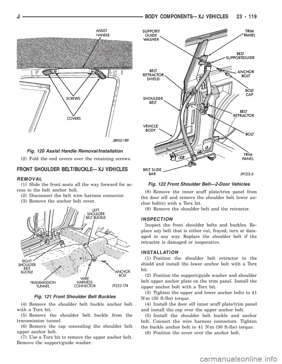
(2) Fold the end covers over the retaining screws.
FRONT SHOULDER BELT/BUCKLEÐXJ VEHICLES
REMOVAL
(1) Slide the front seats all the way forward for ac-
cess to the belt anchor bolt.
(2) Disconnect the belt wire harness connector.
(3) Remove the anchor bolt cover.
(4) Remove the shoulder belt buckle anchor bolt
with a Torx bit.
(5) Remove the shoulder belt buckle from the
transmission tunnel.
(6) Remove the cap concealing the shoulder belt
upper anchor bolt.
(7) Use a Torx bit to remove the upper anchor bolt.
Remove the support/guide washer.(8) Remove the inner scuff plate/trim panel from
the door sill and remove the shoulder belt lower an-
chor bolt(s) with a Torx bit.
(9) Remove the shoulder belt and the retractor.
INSPECTION
Inspect the front shoulder belts and buckles. Re-
place any belt that is either cut, frayed, torn or dam-
aged in any way. Replace the shoulder belt if the
retractor is damaged or inoperative.
INSTALLATION
(1) Position the shoulder belt retractor in the
shield and install the lower anchor bolt with a Torx
bit.
(2) Position the support/guide washer and shoulder
belt upper anchor plate on the trim panel. Install the
upper anchor bolt with a Torx bit.
(3) Tighten the upper and lower anchor bolts to 41
Nzm (30 ft-lbs) torque.
(4) Install the door sill inner scuff plate/trim panel
and install the cap over the upper anchor bolt.
(5) Install the shoulder belt buckle and anchor
bolt. Connect the wire harness connectors. Tighten
the buckle anchor bolt to 41 Nzm (30 ft-lbs) torque.
(6) Position the cover over the anchor bolt.
Fig. 120 Assist Handle Removal/Installation
Fig. 121 Front Shoulder Belt Buckles
Fig. 122 Front Shoulder BeltÐ2-Door Vehicles
JBODY COMPONENTSÐXJ VEHICLES 23 - 119
Page 1650 of 1784
(3) If necessary, remove the retaining screws and
the hinge from the glove box door.
INSTALLATION
(1) If removed, install the hinge on the glove box
door with screws. Tighten the screws securely.
(2) Position the glove box door and hinge on the
glove box housing.
(3) Install the hinge-to-glove box housing screws
and adjust the door for proper fit within the opening.
Tighten the screws securely.
DOOR LATCH STRIKER ADJUSTMENT
The glove box door lock cylinder latch striker is at-
tached to the glove box housing opening with screws.
The striker can be moved in or out for adjustment.
SEATS
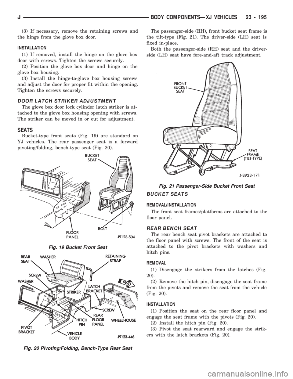
Bucket-type front seats (Fig. 19) are standard on
YJ vehicles. The rear passenger seat is a forward
pivoting/folding, bench-type seat (Fig. 20).The passenger-side (RH), front bucket seat frame is
the tilt-type (Fig. 21). The driver-side (LH) seat is
fixed in-place.
Both the passenger-side (RH) seat and the driver-
side (LH) seat have fore-and-aft track adjustment.
BUCKET SEATS
REMOVAL/INSTALLATION
The front seat frames/platforms are attached to the
floor panel.
REAR BENCH SEAT
The rear bench seat pivot brackets are attached to
the floor panel with screws. The front of the seat is
attached to the pivot brackets with washers and
hitch pins.
REMOVAL
(1) Disengage the strikers from the latches (Fig.
20).
(2) Remove the hitch pin, disengage the seat frame
from the pivots and remove the seat from the vehicle
(Fig. 20).
INSTALLATION
(1) Position the seat on the rear floor panel and
engage the seat frame with the pivots (Fig. 20).
(2) Install the hitch pin (Fig. 20).
(3) Pivot the seat rearward and engage the strik-
ers with the latch brackets (Fig. 20).
Fig. 19 Bucket Front Seat
Fig. 20 Pivoting/Folding, Bench-Type Rear Seat
Fig. 21 Passenger-Side Bucket Front Seat
JBODY COMPONENTSÐXJ VEHICLES 23 - 195
Page 1750 of 1784
CRANKSHAFT POSITION SENSORÐPCM
INPUT.............................14-20
CRANKSHAFT POSITION SENSOR TEST;
FUEL SYSTEM.......................14-44
CRANKSHAFT POSITION SENSOR TEST;
IGNITION SYSTEMS...................8D-9
CROSSMEMBER COVER, FRAME..........13-14
CROSSMEMBER, RADIATOR SUPPORT......23-5
CUSHION AND COVER, BUCKET SEAT......23-98
CUSHION COVERÐXJ VEHICLES, REAR
SEAT .............................23-107
CUSHION, ENGINE FRONT SUPPORT.......13-15
CUSHION RECONDITIONINGÐXJ
VEHICLES, REAR SEAT...............23-108
CUSHIONÐXJ VEHICLES, REAR SEAT.....23-107
CYLINDER BLOCK..................9-45,9-85
CYLINDER BORES, HONING................9-2
CYLINDER COMBUSTION PRESSURE
LEAKAGE TEST DIAGNOSIS...........9-5,9-6
CYLINDER DISPOSAL, LIFTGATE
SUPPORT ROD......................23-70
CYLINDER, DOOR KEY LOCK.............23-54
CYLINDER ENGINE, VACUUM ROUTING
SCHEMATICÐ2.5L 4...................25-2
CYLINDER ENGINE, VACUUM ROUTING
SCHEMATICÐ4.0L 6...................25-3
CYLINDER, FULL-METAL DOOR KEY
LOCK.............................23-178
CYLINDER HEAD COVER, ENGINE......9-18,9-59
CYLINDER HEAD, ENGINE............9-19,9-60
CYLINDER HEAD GASKET FAILURE
DIAGNOSIS, ENGINE....................9-5
CYLINDER INSTALLATION, MASTER....5-20,5-50
CYLINDER INSTALLATION, WHEEL.........5-37
CYLINDER, LIFTGATE SUPPORT ROD......23-69
CYLINDER, MASTER.....................5-40
CYLINDER OVERHAUL, WHEEL............5-36
CYLINDER OVERHAUL, MASTER...........5-20
CYLINDER REMOVAL, MASTER........5-20,5-50
CYLINDER REMOVAL, WHEEL.............5-36
CYLINDER REPLACEMENT, LIFTGATE
LOCK...............................8P-7
CYLINDER, STANDARD MASTER...........5-20
CYLINDER, TAILGATE LOCK.............23-160
CYLINDER/POWER BOOSTER TEST,
MASTER............................5-11
CYLINDER/STRIKER, LIFTGATE LATCH/
KEY LOCK..........................23-68
CYLINDERS, KEY LOCK............23-2,23-132
D RANGE FIRST GEAR, HYDRAULIC
FLOW IN...........................21-87
D RANGE SECOND GEAR, HYDRAULIC
FLOW IN...........................21-88
D RANGE THIRD GEAR, HYDRAULIC
FLOW IN...........................21-89
DAMAGE TORQUE, COLLISION............13-1
DAMAGED OR WORN THREADS, REPAIR.....9-4
DAMPENER, STEERING............19-15,19-18
DAMPER, ENGINE......................9-13
DAMPER, VIBRATION................9-26,9-67
DASH PANEL INSULATION PANEL.........23-95
DASH PANEL INSULATOR PANEL.........23-11
DATA LINK CONNECTORÐPCM INPUT.....14-20
DATA LINK CONNECTORÐPCM OUTPUT....14-24
DATA, VEHICLE DIMENSION . . . INTRO.-3,INTRO.-4
DATA, VEHICLE LOAD................INTRO.-3
DATA, XJ VEHICLE LOAD.............INTRO.-5
DATA, YJ-VEHICLE LOAD.............INTRO.-6
DAYTIME RUNNING LIGHTS (CANADA
ONLY) .............................8L-16
DECODING, VEHICLE CODE...........INTRO.-3
DECODING, VEHICLE IDENTIFICATION
NUMBER (VIN)....................INTRO.-2
DEFLECTOR, COWL WEATHERSTRIP
SEAL/CROSSMEMBER AIR.............23-10
DEFOGGER GRID REPAIR, REAR
WINDOW............................8N-2
DEFOGGER GRID TEST, REAR
WINDOW............................8N-1
DEFOGGER, REAR WINDOW..............8A-1
DEFOGGER RELAY, REAR
................8N-4
DEFOGGER SWITCH REPLACEMENT,
REAR WINDOW
.......................8N-4
DEFOGGER/FOG LAMP/REAR WIPER
SWITCHES, REAR
....................8E-21
DEFROSTER DUCT REPLACEMENT
........24-29DEFROSTER NOZZLE AND DUCT..........24-40
DELAY FUNCTION TROUBLE
DIAGNOSISÐXJ VEHICLES, HEADLAMP . . . 8L-16
DELAY MODULE REPLACEMENTÐXJ
VEHICLES, HEADLAMP................8L-16
DELAY MODULEÐXJ VEHICLES,
SENTINEL HEADLAMP.................8L-15
DELIVERY SYSTEM, FUEL................14-2
DEPTH INFORMATION, PINION GEAR;
FRONT SUSPENSION AND AXLE..........2-37
DEPTH INFORMATION, PINION GEAR;
REAR SUSPENSION AND AXLES..........3-19
DEPTH VARIANCE, PINION GEAR; FRONT
SUSPENSION AND AXLE................2-38
DEPTH VARIANCE, PINION GEAR; REAR
SUSPENSION AND AXLES...........3-20,3-38
DESCRIPTION (AIR CONDITIONING).......24-41
DESCRIPTION; AUDIO SYSTEMS...........8F-1
DESCRIPTION (HEATING)................24-37
DESCRIPTION; HEATING AND AIR
CONDITIONING.................24-17,24-22
DESCRIPTION; OVERHEAD CONSOLE.......8C-1
DESCRIPTION; POWER DOOR LOCKS.......8P-1
DESCRIPTION; POWER WINDOWS.........8S-1
DESCRIPTION; TRANSMISSION AND
TRANSFER CASE....................21-156
DESCRIPTION; TURN SIGNALS AND
HAZARD WARNING FLASHER........8J-1,8J-2
DESCRIPTION/SYSTEM OPERATION,
MULTI-PORT FUEL INJECTION (MFI)Ð
COMPONENT........................14-17
DESIGNATION CODES, VEHICLE........INTRO.-1
DESIGNATIONS, LABELS/PLATES, CODES
AND DIMENSIONS.................INTRO.-1
DESIGNATIONS, VEHICLE.............INTRO.-1
DETECTION AND REPAIR, FIXED GLASS
WATER LEAK..................23-83,23-189
DIAGNOSING INTERMITTENT
WINDSHIELD WASHER................8K-12
DIAGNOSING NON-INTERMITTENT
WINDSHIELD WASHER................8K-12
DIAGNOSING PARKING BRAKE
PROBLEMS..........................5-10
DIAGNOSING POWER DOOR LOCKS....8P-1,8P-9
DIAGNOSING REAR WIPER...............8K-6
DIAGNOSING REAR WIPER WASHER.......8K-6
DIAGNOSING REAR WIPER/WASHER......8K-14
DIAGNOSING SERVICE BRAKE
PROBLEMS...........................5-8
DIAGNOSING WINDSHIELD WASHER
(INTERMITTENT)......................8K-4
DIAGNOSING WINDSHIELD WASHER
(NON-INTERMITTENT)..................8K-4
DIAGNOSING WINDSHIELD WIPERS . . . 8K-3,8K-11
DIAGNOSINGÐALL LAMPS OUT..........8E-16
DIAGNOSINGÐTURN SIGNAL
INOPERATIVE.........................8J-2
DIAGNOSIS, 2.5L STARTER MOTOR NOISE . . . 8A-13
DIAGNOSIS, 30RH/32RH TRANSMISSION . . 21-69,
21-77,21-78,21-79,21-80,21-81,21-82,21-83,21-84,
21-85
DIAGNOSIS, ABS BRAKE..................5-3
DIAGNOSIS, ABS FAULT................5-4,5-6
DIAGNOSIS, AIR CONDITIONING
SYSTEM............................24-12
DIAGNOSIS AND REPAIR............8G-1,8G-2
DIAGNOSIS; AUDIO SYSTEMS.............8F-1
DIAGNOSIS, AW-4 TRANSMISSION
.......21-167
DIAGNOSIS, AXLE NOISE/VIBRATION;
FRONT SUSPENSION AND AXLE
..........2-16
DIAGNOSIS, AXLE NOISE/VIBRATION;
REAR SUSPENSION AND AXLES
..........3-7
DIAGNOSIS, BELT
.......................7-31
DIAGNOSIS CHARTS, INSPECTION
..........6-4
DIAGNOSIS; CHIME/BUZZER WARNING
SYSTEMS
...........................8U-1
DIAGNOSIS, CLUTCH
.....................6-3
DIAGNOSIS, COMPRESSOR
..............24-13
DIAGNOSIS, CONVERTER HOUSING
LEAK
..............................21-73
DIAGNOSIS; COOLING SYSTEM
.............7-4
DIAGNOSIS, CYLINDER COMBUSTION
PRESSURE LEAKAGE TEST
...............9-6
DIAGNOSIS, DISCONNECT AXLE/SHIFT
MOTOR
.............................2-27DIAGNOSIS, DOME/COURTESY LAMP
TROUBLE...........................8L-19
DIAGNOSIS, ECU........................5-4
DIAGNOSISÐELECTRICAL, SERVICE.......24-14
DIAGNOSIS, ENGINE.....................9-5
DIAGNOSIS, ENGINE CYLINDER HEAD
GASKET FAILURE......................9-5
DIAGNOSIS, EXHAUST SYSTEM............11-2
DIAGNOSIS, FOG LAMP TROUBLE.........8L-12
DIAGNOSIS, GAUGE PACKAGE............8E-22
DIAGNOSIS, GEAR LEAKAGE..............19-8
DIAGNOSIS GUIDES AND CHARTS........21-76
DIAGNOSISÐHAZARD LAMPS
INOPERATIVE.....................8J-1,8J-2
DIAGNOSIS, HCU........................5-4
DIAGNOSIS, HEATING SYSTEM...........24-11
DIAGNOSIS, IGNITION OFF DRAW (IOD).....8A-8
DIAGNOSIS, IGNITION SECONDARY
CIRCUIT...........................8D-12
DIAGNOSIS, ILLUMINATED ENTRY
SYSTEM TROUBLE..............8L-21,8L-22
DIAGNOSIS INFORMATION, GENERAL;
CLUTCH..............................6-3
DIAGNOSIS INFORMATION, GENERAL;
TRANSMISSION AND TRANSFER
CASE.............................21-167
DIAGNOSIS, INSTRUMENT CLUSTER;
INSTRUMENT PANEL AND
GAUGESÐXJ.........................8E-3
DIAGNOSIS, INSTRUMENT CLUSTER;
INSTRUMENT PANEL AND
GAUGESÐYJ........................8E-14
DIAGNOSIS, INTAKE MANIFOLD LEAKAGE.....9-5
DIAGNOSIS, LIGHTED VANITY MIRROR
TROUBLE...........................8L-19
DIAGNOSIS, MANUAL STEERING
SYSTEM............................19-36
DIAGNOSISÐMECHANICAL, SERVICE;
ENGINES.............................9-8
DIAGNOSISÐMECHANICAL, SERVICE;
HEATING AND AIR CONDITIONING........24-8
DIAGNOSIS, MULTI-PORT FUEL
INJECTION (MFI)ÐGENERAL...........14-32
DIAGNOSIS, NOISE.....................3-45
DIAGNOSIS, NP231 SERVICE............21-274
DIAGNOSIS, NP242 SERVICE............21-295
DIAGNOSIS, PERFORMANCE.............24-10
DIAGNOSIS; POWER MIRRORS............8T-1
DIAGNOSIS; POWER SEATS..............8R-1
DIAGNOSIS, POWER STEERING SYSTEM....19-3,
19-4,19-5,19-6,19-7
DIAGNOSIS, PRELIMINARY..............21-69
DIAGNOSIS, PRESSURE..................24-9
DIAGNOSIS PROCEDURES; BRAKES......5-3,5-7
DIAGNOSIS, PUMP LEAKAGE..............19-8
DIAGNOSIS, RADIO NOISE................8F-2
DIAGNOSIS; REAR WINDOW DEFOGGER....8N-2
DIAGNOSIS, SERPENTINE DRIVE BELT......7-32
DIAGNOSIS, SERVICE BRAKE..............5-7
DIAGNOSIS, SERVICE; FRONT
SUSPENSION AND AXLE................2-18
DIAGNOSIS, SERVICE; REAR
SUSPENSION AND AXLES................3-9
DIAGNOSIS, SERVICE; TRANSMISSION
AND TRANSFER CASE . 21-2,21-33,21-171,21-172
DIAGNOSIS, SPRING AND SHOCK;
FRONT SUSPENSIONAND AXLE
......2-12,2-14
DIAGNOSIS, SPRING AND SHOCK; REAR
SUSPENSIONAND AXLES
.............3-3,3-5
DIAGNOSIS, STARTING SYSTEM
..........8A-10
DIAGNOSIS; STEERING
.................19-35
DIAGNOSIS, SUSPENSION AND
STEERING SYSTEM
.....................2-7
DIAGNOSIS, SYSTEM
.....................7-7
DIAGNOSISÐTURN SIGNAL
INOPERATIVE
.........................8J-1
DIAGNOSISÐVEHICLE RUNS ROUGH
AND/OR HAS A MISS, INJECTOR
........14-49
DIAGNOSIS, VIBRATION
.............22-9,22-10
DIAGNOSISÐXJ VEHICLES, HEADLAMP
DELAY FUNCTION TROUBLE
............8L-16
DIAGNOSISÐXJ VEHICLES, HEADLAMP
TROUBLE
............................8L-1
DIAGNOSISÐYJ VEHICLES,
HEADLAMP TROUBLE
..................8L-2
6 INDEXJ
Description Group-Page Description Group-Page Description Group-Page