1994 JEEP CHEROKEE check transmission fluid
[x] Cancel search: check transmission fluidPage 6 of 1784

MAINTENANCE SCHEDULES
INTRODUCTION
Chrysler Corporation has compiled recommended
lubrication and maintenance schedules and proce-
dures to help reduce premature wear or failure over
a broad range of operating conditions.
SEVERE SERVICE MAINTENANCE
If the vehicle is involved with a severe driving con-
dition, after each 4 800-km (3,000-miles)/3-month in-
terval. A severe driving condition includes:
²frequent short trip driving less than 24 km (15
miles);
²frequent driving in a dusty environment;
²trailer towing;
²extensive engine idling;
²sustained high-speed operation;
²desert operation;
²frequent starting and stopping;
²cold-climate operation;
²off-road driving; or
²commercial service.
MAINTENANCE SCHEDULES
AT EACH STOP FOR FUEL
²Check engine oil level, add as required.
²
Check windshield washer solvent and add if required.
ONCE A MONTH
²Check tire pressure and look for unusual wear or
damage.
²Inspect battery and clean and tighten terminals as
required.
²Check electrolyte level and add water as needed.
²Check fluid levels of coolant reservoir, power steer-
ing and transmission and add as needed.
²Check all lights and all other electrical items for
correct operation.
²Check rubber seals on each side of the radiator for
proper fit.
7,500 MILES (12 000 KM) OR AT 6 MONTHS
²Check engine coolant level, hoses and clamps.
²Change engine oil.
²Replace engine oil filter.
²Check exhaust system.
²Lubricate steering linkage (4x4 models).
²Lubricate propeller shaft universal joints.
²Rotate Tires.
15,000 MILES (24 000 KM) OR AT 12 MONTHS
²Check engine coolant level, hoses and clamps.
²Change engine oil.
²Replace engine oil filter.
²Check exhaust system.
²Lubricate steering linkage (4x4 models).
²Lubricate propeller shaft universal joints.²Check fluid level in battery.
²Rotate Tires.
22,500 MILES (36 000 KM) OR AT 18 MONTHS
²Check engine coolant level, hoses and clamps.
²Change engine oil.
²Replace engine oil filter.
²Check exhaust system.
²Lubricate steering linkage (4x4 models).
²Lubricate propeller shaft universal joints.
²Rotate Tires.
30,000 MILES (48 000 KM) OR AT 24 MONTHS
²Replace air cleaner filter.
²Replace spark plugs.
²Adjust drive belt.
²Check engine coolant level, hoses and clamps.
²Change engine oil.
²Replace engine oil filter.
²Check exhaust system.
²Lubricate steering linkage (4x4 models).
²Lubricate propeller shaft universal joints.
²Check fluid level in battery.
²Drain and refill automatic transmission.
²Drain and refill transfer case.
²Rotate Tires.
37,500 MILES (60 000 KM) OR AT 30 MONTHS
²Check engine coolant level, hoses and clamps.
²Change engine oil.
²Replace engine oil filter.
²Check exhaust system.
²Lubricate steering linkage (4x4 models).
²Lubricate propeller shaft universal joints.
²Drain and refill manual transmission.
²Rotate Tires.
45,000 MILES (72 500 KM) OR AT 36 MONTHS
²Check engine coolant level, hoses and clamps.
²Change engine oil.
²Replace engine oil filter.
²Check exhaust system.
²Lubricate steering linkage (4x4 models).
²Lubricate propeller shaft universal joints.
²Check fluid level in battery.
²Rotate Tires.
52,500 MILES (84 500 KM) OR AT 42 MONTHS
²Flush and replace engine coolant.
²Check engine coolant system hoses and clamps.
²Change engine oil.
²Replace engine oil filter.
²Check exhaust system.
²Lubricate steering linkage (4x4 models).
²Lubricate propeller shaft universal joints.
²Rotate Tires.
JLUBRICATION AND MAINTENANCE 0 - 5
Page 7 of 1784

60,000 MILES (96 500 KM) OR AT 48 MONTHS.
²Replace air cleaner filter.
²Replace distributor cap and rotor.
²Replace ignition wires.
²Replace spark plugs.
²Adjust or replace drive belt.
²Check engine coolant level, hoses and clamps.
²Change engine oil.
²Replace engine oil filter.
²Check exhaust system.
²Replace fuel filter (not required for Calif. vehicles).
²Lubricate steering linkage (4x4 models).
²Lubricate propeller shaft universal joints.
²Check fluid level in battery.
²Drain and refill automatic transmission.
²Drain and refill transfer case.
²Rotate Tires.
67,500 MILES (108 500 KM) OR AT 54
MONTHS
²Check engine coolant level, hoses and clamps.
²Change engine oil.
²Replace engine oil filter.
²Check exhaust system.
²Lubricate steering linkage (4x4 models).
²Lubricate propeller shaft universal joints.
²Rotate Tires.
75,000 MILES (120 500 KM) OR AT 60
MONTHS
²Check engine coolant level, hoses and clamps.
²Change engine oil.
²Replace engine oil filter.
²Check exhaust system.
²Lubricate steering linkage (4x4 models).
²Lubricate propeller shaft universal joints.
²Drain and refill manual transmission.
²Rotate Tires.
82,500 MILES (133 000 KM) OR AT 66
MONTHS
²Flush and replace engine coolant.
²Check engine coolant system, hoses and clamps.
²Change engine oil.
²Replace engine oil filter.
²Check exhaust system.
²Lubricate steering linkage (4x4 models).
²Lubricate propeller shaft universal joints.
²Rotate Tires.
90,000 MILES (145 000 KM) OR AT 72
MONTHS
²Replace air cleaner filter.
²Replace spark plugs.
²Adjust drive belt.
²Check engine coolant level, hoses and clamps.
²Change engine oil.
²Replace engine oil filter.²Check exhaust system.
²Lubricate steering linkage (4x4 models).
²Lubricate propeller shaft universal joints.
²Check fluid level in battery.
²Drain and refill automatic transmission.
²Drain and refill transfer case.
²Rotate Tires.
97,500 MILES (157 000 KM) OR AT 78
MONTHS
²Check engine coolant level, hoses and clamps.
²Change engine oil.
²Replace engine oil filter.
²Check exhaust system.
²Lubricate steering linkage (4x4 models).
²Lubricate propeller shaft universal joints.
²Rotate Tires.
105,000 MILES (169 000 KM) OR AT 84
MONTHS
²Check engine coolant level, hoses and clamps.
²Change engine oil.
²Replace engine oil filter.
²Check exhaust system.
²Lubricate steering linkage (4x4 models).
²Lubricate propeller shaft universal joints.
²Rotate Tires.
112,500 MILES (181 000 KM) OR AT 90
MONTHS
²Flush and replace engine coolant.
²Check engine coolant system hoses and clamps.
²Change engine oil.
²Replace engine oil filter.
²Check exhaust system.
²Lubricate steering linkage (4x4 models).
²Lubricate propeller shaft universal joints.
²Rotate Tires.
120,000 MILES (193 000 KM) OR AT 96
MONTHS
²Replace air cleaner filter.
²Replace distributor cap and rotor.
²Replace ignition wires.
²Replace spark plugs.
²Adjust or replace drive belt.
²Check engine coolant level, hoses and clamps.
²Change engine oil.
²Replace engine oil filter.
²Check exhaust system.
²Replace fuel filter (not required for Calif. vehicles).
²Lubricate steering linkage (4x4 models).
²Lubricate propeller shaft universal joints.
²Check fluid level in battery.
²Drain and refill automatic transmission.
²Drain and refill transfer case.
²Rotate Tires.
0 - 6 LUBRICATION AND MAINTENANCEJ
Page 13 of 1784
When the transfer case is in the NEUTRAL po-
sition, both axles are disengaged from the pow-
ertrain. This allows the vehicle to be towed
without removing the drive shafts.
(2) Shift the transfer case to NEUTRAL.
(3) The vehicle can now be towed with the front
wheels raised (refer to Sling-Type, Front-End Tow-
ing).
VEHICLE DOORS LOCKED
Place a tow dolly under the rear wheels (Fig. 14)
and tow with the front end raised (refer to Sling-
Type, Front-End Towing).
4WD EMERGENCY TOWINGÐTRANSFER CASE
NOT SHIFTED TO NEUTRAL
When a situation arises and the transfer case can-
not be shifted to NEUTRAL, any of the following
methods can be used to tow a 4WD vehicle.
Drive shafts not removed, place the rear
wheels on a tow dolly and tow with the front
end raised.
Drive shafts not removed, place the front
wheels on a tow dolly and tow with the rear end
raised.
Rear drive shaft removed, tow with the front
end raised.
Front drive shaft removed, tow with the rear
end raised.
Both drive shafts removed, tow with all four
wheels on the road surface.
(1) Turn ignition key switch to the unlocked (OFF)
position.
(2) Shift the transmission to the NEUTRAL posi-
tion.
(3) Determine the method by which the vehicle
will be towed and prepare the vehicle for towing.
(4) Connect the vehicle to the tow vehicle. Refer to
the applicable procedure.
FLAT TOWING (4 TIRES/WHEELS ON
SURFACE)
Tow a vehicle in this manner only when all four
wheels will freely rotate. Prepare the vehicle accord-
ing to the following procedures.
2WD VEHICLES
(1) Mark the drive shaft and the axle drive pinion
gear shaft yoke for installation alignment reference.
(2) Remove the drive shaft. Install a protective
covering over the drive shaft U-joints to retain them
assembled and protected.
(3) Cover the open end of the transmission exten-
sion housing.4WD VEHICLES
(1) Mark the drive shafts and the axle drive pinion
gear shaft yokes for installation alignment reference.
(2) Remove the drive shafts. Install a protective
covering over the drive shaft U-joints/CV-joints to re-
tain them assembled and protected.
(3) Cover the exposed ends of the transfer case.
CAUTION: Whenever a drive shaft has been re-
moved and installed, check the transmission fluid
level of the transmission and transfer case. Driving
a vehicle with low tranfer case fluid can damage the
transmission and transfer case.
EMERGENCY TOW HOOKS
WARNING: REMAIN AT A SAFE DISTANCE FROM A
VEHICLE THAT IS BEING TOWED VIA ITS TOW
HOOKS. THE TOW STRAPS/CHAINS COULD POSSI-
BLY BREAK AND CAUSE SERIOUS INJURY.
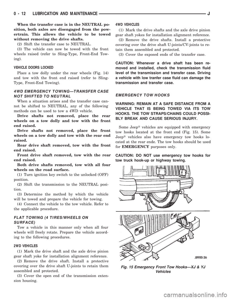
Some Jeeptvehicles are equipped with emergency
tow hooks located at the front end (Fig. 15). Some
Jeeptvehicles also have emergency tow hooks lo-
cated at the rear ende. The tow hooks should be used
forEMERGENCYpurposes only.
CAUTION: DO NOT use emergency tow hooks for
tow truck hook-up or highway towing.
Fig. 15 Emergency Front Tow HooksÐXJ & YJ
Vehicles
0 - 12 LUBRICATION AND MAINTENANCEJ
Page 23 of 1784
DRIVETRAIN
INDEX
page page
Automatic Transmission.................... 23
Drive Shafts............................ 27
Front and Rear Axles..................... 26
Hydraulic Clutch......................... 22Manual Transmission...................... 22
Rubber and Plastic Hoses/Tubing............ 28
Transfer Case........................... 25
HYDRAULIC CLUTCH
RECOMMENDED MAINTENANCE
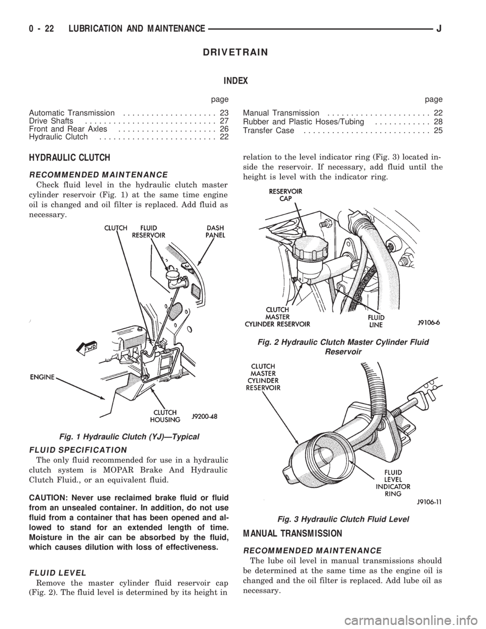
Check fluid level in the hydraulic clutch master
cylinder reservoir (Fig. 1) at the same time engine
oil is changed and oil filter is replaced. Add fluid as
necessary.
FLUID SPECIFICATION
The only fluid recommended for use in a hydraulic
clutch system is MOPAR Brake And Hydraulic
Clutch Fluid., or an equivalent fluid.
CAUTION: Never use reclaimed brake fluid or fluid
from an unsealed container. In addition, do not use
fluid from a container that has been opened and al-
lowed to stand for an extended length of time.
Moisture in the air can be absorbed by the fluid,
which causes dilution with loss of effectiveness.
FLUID LEVEL
Remove the master cylinder fluid reservoir cap
(Fig. 2). The fluid level is determined by its height inrelation to the level indicator ring (Fig. 3) located in-
side the reservoir. If necessary, add fluid until the
height is level with the indicator ring.
MANUAL TRANSMISSION
RECOMMENDED MAINTENANCE
The lube oil level in manual transmissions should
be determined at the same time as the engine oil is
changed and the oil filter is replaced. Add lube oil as
necessary.
Fig. 1 Hydraulic Clutch (YJ)ÐTypical
Fig. 2 Hydraulic Clutch Master Cylinder Fluid
Reservoir
Fig. 3 Hydraulic Clutch Fluid Level
0 - 22 LUBRICATION AND MAINTENANCEJ
Page 24 of 1784
Under normal driving conditions, manual trans-
mission lube oil should be changed after each 60
000-km (37,500 miles). With severe driving condi-
tions, after each 29 000-km (18,000 miles).
LUBRICANT SPECIFICATION
When it becomes necessary to add to or change the
lube oil in a Jeeptmanual transmission, use SAE
75W-90, API Quality Grade GL-5 gear lubricant.
LUBRICANT LEVEL
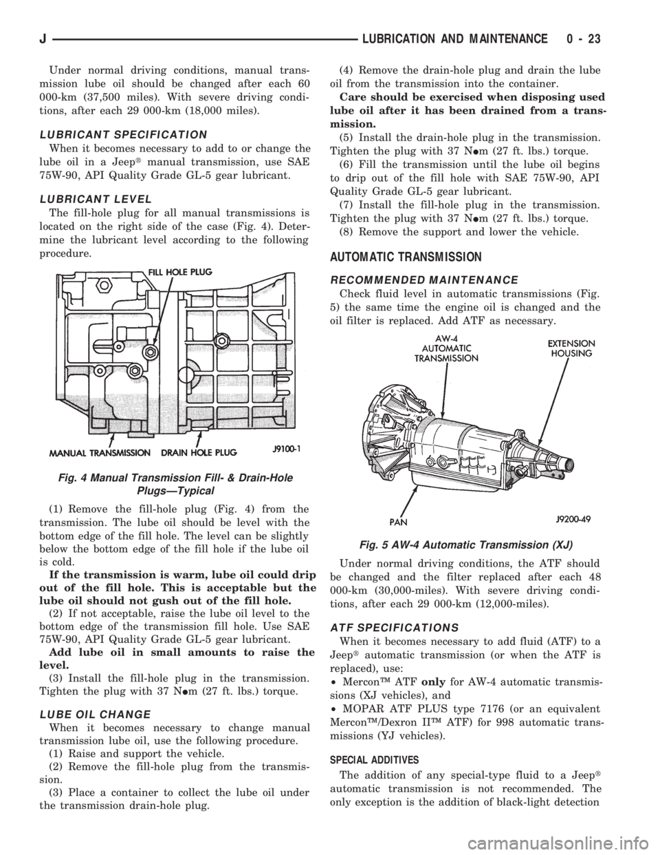
The fill-hole plug for all manual transmissions is
located on the right side of the case (Fig. 4). Deter-
mine the lubricant level according to the following
procedure.
(1) Remove the fill-hole plug (Fig. 4) from the
transmission. The lube oil should be level with the
bottom edge of the fill hole. The level can be slightly
below the bottom edge of the fill hole if the lube oil
is cold.
If the transmission is warm, lube oil could drip
out of the fill hole. This is acceptable but the
lube oil should not gush out of the fill hole.
(2) If not acceptable, raise the lube oil level to the
bottom edge of the transmission fill hole. Use SAE
75W-90, API Quality Grade GL-5 gear lubricant.
Add lube oil in small amounts to raise the
level.
(3) Install the fill-hole plug in the transmission.
Tighten the plug with 37 NIm (27 ft. lbs.) torque.
LUBE OIL CHANGE
When it becomes necessary to change manual
transmission lube oil, use the following procedure.
(1) Raise and support the vehicle.
(2) Remove the fill-hole plug from the transmis-
sion.
(3) Place a container to collect the lube oil under
the transmission drain-hole plug.(4) Remove the drain-hole plug and drain the lube
oil from the transmission into the container.
Care should be exercised when disposing used
lube oil after it has been drained from a trans-
mission.
(5) Install the drain-hole plug in the transmission.
Tighten the plug with 37 NIm (27 ft. lbs.) torque.
(6) Fill the transmission until the lube oil begins
to drip out of the fill hole with SAE 75W-90, API
Quality Grade GL-5 gear lubricant.
(7) Install the fill-hole plug in the transmission.
Tighten the plug with 37 NIm (27 ft. lbs.) torque.
(8) Remove the support and lower the vehicle.
AUTOMATIC TRANSMISSION
RECOMMENDED MAINTENANCE
Check fluid level in automatic transmissions (Fig.
5) the same time the engine oil is changed and the
oil filter is replaced. Add ATF as necessary.
Under normal driving conditions, the ATF should
be changed and the filter replaced after each 48
000-km (30,000-miles). With severe driving condi-
tions, after each 29 000-km (12,000-miles).
ATF SPECIFICATIONS
When it becomes necessary to add fluid (ATF) to a
Jeeptautomatic transmission (or when the ATF is
replaced), use:
²MerconŸ ATFonlyfor AW-4 automatic transmis-
sions (XJ vehicles), and
²MOPAR ATF PLUS type 7176 (or an equivalent
MerconŸ/Dexron IIŸ ATF) for 998 automatic trans-
missions (YJ vehicles).
SPECIAL ADDITIVES
The addition of any special-type fluid to a Jeept
automatic transmission is not recommended. The
only exception is the addition of black-light detection
Fig. 5 AW-4 Automatic Transmission (XJ)
Fig. 4 Manual Transmission Fill- & Drain-Hole
PlugsÐTypical
JLUBRICATION AND MAINTENANCE 0 - 23
Page 143 of 1784
(3) Lower the vehicle.
PARK NEUTRAL SWITCH
Refer to Group 21, Transmissions for park neutral
switch service.
POWER STEERING PRESSURE SWITCHÐ2.5L
ENGINE ONLY
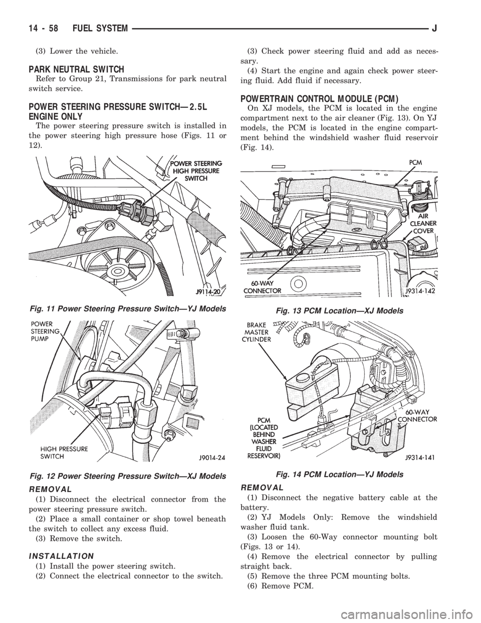
The power steering pressure switch is installed in
the power steering high pressure hose (Figs. 11 or
12).
REMOVAL
(1) Disconnect the electrical connector from the
power steering pressure switch.
(2) Place a small container or shop towel beneath
the switch to collect any excess fluid.
(3) Remove the switch.
INSTALLATION
(1) Install the power steering switch.
(2) Connect the electrical connector to the switch.(3) Check power steering fluid and add as neces-
sary.
(4) Start the engine and again check power steer-
ing fluid. Add fluid if necessary.
POWERTRAIN CONTROL MODULE (PCM)
On XJ models, the PCM is located in the engine
compartment next to the air cleaner (Fig. 13). On YJ
models, the PCM is located in the engine compart-
ment behind the windshield washer fluid reservoir
(Fig. 14).
REMOVAL
(1) Disconnect the negative battery cable at the
battery.
(2) YJ Models Only: Remove the windshield
washer fluid tank.
(3) Loosen the 60-Way connector mounting bolt
(Figs. 13 or 14).
(4) Remove the electrical connector by pulling
straight back.
(5) Remove the three PCM mounting bolts.
(6) Remove PCM.
Fig. 11 Power Steering Pressure SwitchÐYJ Models
Fig. 12 Power Steering Pressure SwitchÐXJ Models
Fig. 13 PCM LocationÐXJ Models
Fig. 14 PCM LocationÐYJ Models
14 - 58 FUEL SYSTEMJ
Page 155 of 1784
(2) If red warning light is illuminated, or if neither
warning light is illuminated, make several stops and
note pedal action and brake response.
(3) Check brake pedal response with transmission
in Neutral and engine running. Pedal should remain
firm under steady foot pressure. If pedal falls away,
problem is either in vacuum booster or master cylin-
der.
(4) During road test, make normal and firm brake
stops in 25-40 mph range. Note faulty brake opera-
tion such as pull, grab, drag, noise, fade, pedal pul-
sation, etc.
(5) Inspect suspect brake components and refer to
problem diagnosis information for causes of various
brake conditions.
COMPONENT INSPECTION
Fluid leak points and dragging brake units can
usually be located without removing any compo-
nents. The area around a leak point will be wet with
fluid. The components at a dragging brake unit
(wheel, tire, rotor) will be quite warm or hot to the
touch.
Other brake problem conditions will require compo-
nent removal for proper inspection. Raise the vehicle
and remove the necessary wheels for better visual ac-
cess.
During component inspection, pay particular atten-
tion to heavily rusted/corroded brake components
(e.g. rotors, caliper pistons, brake return/holddown
springs, support plates, etc.).
Heavy accumulations of rust may be covering se-
vere damage to a brake component. It is wise to re-
move surface rust in order to accurately determine
the depth of rust penetration and damage. Light sur-
face rust is fairly normal and not a major concern (as
long as it is removed). However, heavy rust buildup,
especially on high mileage vehicles may cover struc-
tural damage to such important components as
brakelines, rotors, support plates, and brake boosters.
Refer to the wheel brake service procedures in this
group for more information.
DIAGNOSING SERVICE BRAKE PROBLEMS
BRAKE WARNING LIGHT OPERATION
The red brake warning light will illuminate under
the following conditions:
²for 2-3 seconds at startup as part of normal bulb
check
²parking brakes applied
²low pedal caused by malfunction in front/rear
brake hydraulic circuit (differential switch valve ac-
tuated)
If the red light remains on after startup, first ver-
ify that the parking brakes are fully released. Then
check pedal action and fluid level. A red light indi-
cates that the valve in the differential pressureswitch has been actuated. If a problem is confirmed,
inspect the hydraulic system and wheel brake compo-
nents.
On models with ABS brakes, the amber warning
light only illuminates when an ABS component has
malfunctioned. The ABS light operates indepen-
dently of the red warning light. Refer to the antilock
brake section for more detailed diagnosis informa-
tion.
PEDAL FALLS AWAY
A brake pedal that falls away under steady foot
pressure is generally the result of a system leak. The
leak point could be at a brakeline, fitting, hose,
wheel cylinder, or caliper. Internal leakage in the
master cylinder caused by worn or damaged piston
cups, may also be the problem cause.
If leakage is severe, fluid will be evident at or
around the leaking component. However internal
leakage in the master cylinder will not be physically
evident. Refer to the cylinder test procedure in this
section.
LOW PEDAL
If a low pedal is experienced, pump the pedal sev-
eral times. If the pedal comes back up, worn lining
and worn rotors or drums are the most likely causes.
However, if the pedal remains low and/or the warn-
ing light illuminates, the problem is in the master
cylinder, wheel cylinders, or calipers.
A decrease in master cylinder fluid level may only
be the result of normal lining wear. Fluid level will
decrease as lining wear occurs. It is a result of the
outward movement of caliper and wheel cylinder pis-
tons to compensate for normal wear.
SPONGY PEDAL
A spongy pedal is most often caused by air in the
system. However, thin drums or substandard brake
lines and hoses will also cause a condition similar to
a spongy pedal. The proper course of action is to
bleed the system, or replace thin drums and suspect
quality brake lines and hoses.
HARD PEDAL OR HIGH PEDAL EFFORT
A hard pedal or high pedal effort may be due to
lining that is water soaked, contaminated, glazed, or
badly worn. The power booster or check valve could
also be faulty. Test the booster and valve as de-
scribed in this section.
BRAKE DRAG
Brake drag occurs when the lining is in constant
contact with the rotor or drum. Drag can occur at
one wheel, all wheels, fronts only, or rears only. It is
a product of incomplete brakeshoe release. Drag can
be minor or severe enough to overheat the linings,
rotors and drums.
5 - 8 BRAKESJ
Page 218 of 1784
CLUTCH DIAGNOSIS
INDEX
page page
Clutch Problem Causes..................... 3
General Diagnosis Information................ 3Inspection and Diagnosis Charts.............. 4
GENERAL DIAGNOSIS INFORMATION
Unless the cause of a clutch problem is obvious, ac-
curate problem diagnosis will usually require a road
test to confirm a problem. Component inspection will
then be required to determine the actual problem
cause.
During a road test, drive the vehicle at normal
speeds. Shift the transmission through all gear
ranges and observe clutch action. If chatter, grab,
slip, or improper release is experienced, remove and
inspect the clutch components. However, if the prob-
lem is noise or hard shifting, further diagnosis may
be needed as the transmission or another driveline
component may be at fault. Careful observation dur-
ing the test will help narrow the problem area.
CLUTCH PROBLEM CAUSES
CONTAMINATION
Fluid contamination is a frequent cause of clutch
malfunctions. Oil, water, or clutch fluid on the clutch
contact surfaces will cause faulty operation. The
usual result is chatter, slip and grab.
During inspection, note if any components are con-
taminated with oil, hydraulic fluid, or water/road
splash.
Oil contamination indicates a leak at either the
rear main seal or transmission input shaft. Oil leak-
age produces a residue of oil on the housing interior
and on the clutch cover and flywheel. Heat buildup
caused by slippage between the cover, disc and fly-
wheel, can sometimes bake the oil residue onto the
components. The glaze-like residue ranges in color
from amber to black.
Road splash contamination means dirt/water is en-
tering the clutch housing due to loose bolts, housing
cracks, or through hydraulic line openings. Driving
through deep water puddles can force water/road
splash into the housing through such openings.
Clutch fluid leaks are from loose or damaged slave
cylinder fluid lines and connecting fittings. However,
clutch fluid leaks will usually be noted and corrected
before severe contamination occurs.
CLUTCH MISALIGNMENT
Clutch components must be in proper alignment
with the crankshaft and transmission input shaft.Misalignment caused by excessive runout or warpage
of any clutch component will cause grab, chatter and
improper clutch release.
Flywheel Runout
Check flywheel runout whenever misalignment is
suspected. Flywheel runout should not exceed 0.08
mm (0.003 in.). Measure runout at the outer edge of
the flywheel face with a dial indicator. Mount the in-
dicator on a stud installed in place of one of the fly-
wheel bolts.
Common causes of runout are:
²heat warpage
²improper machining
²incorrect bolt tightening
²improper seating on crankshaft flange shoulder
²foreign material on crankshaft flange
Flywheel machining is not recommended. The fly-
wheel clutch surface is machined to a unique contour
and machining will negate this feature. However,
minor flywheel scoring can be cleaned up by hand
with 180 grit emery, or with surface grinding equip-
ment. Remove only enough material to reduce scor-
ing (approximately 0.001 - 0.003 in.). Heavy stock
removal isnot recommended.Replace the flywheel
if scoring is severe and deeper than 0.076 mm (0.003
in.). Excessive stock removal can result in flywheel
cracking or warpage after installation; it can also
weaken the flywheel and interfere with proper clutch
release.
Clean the crankshaft flange before mounting the
flywheel. Dirt and grease on the flange surface may
cock the flywheel causing excessive runout. Use new
bolts when remounting a flywheel and secure the
bolts with Mopar Lock And Seal. Tighten flywheel
bolts to specified torque only. Overtightening can dis-
tort the flywheel hub causing runout.
Clutch Cover And Disc Runout
Check the clutch disc before installation. Axial
(face) runout of anewdisc should not exceed 0.50
mm (0.020 in.). Measure runout about 6 mm (1/4 in.)
from the outer edge of the disc facing. Obtain an-
other disc if runout is excessive.
Check condition of the clutch before installation. A
warped cover or diaphragm spring will cause grab
and incomplete release or engagement. Be careful
JCLUTCH DIAGNOSIS 6 - 3