1994 JEEP CHEROKEE hood release
[x] Cancel search: hood releasePage 35 of 1784
(6) Inspect the disc brake caliper dust boot for cor-
rect installation, damage/tears and indications of
brake fluid leakage. Inspect the bushings and pins
for corrosion, tears and a binding condition.
(7) Pull the rear wheel cylinder dust boot back to
expose the wheel cylinder housing and inspect for
fluid leaks. Inspect the pistons and cylinder bores for
proper appearance.
(8) Inspect the brake differential warning valve
and housing for indications of leakage, kinked hoses
and loose fittings.
PARK BRAKE
(1) As applicable, engage the park brake lever or
pedal and then release it.
(2) If the park brake is functioning normally, test
it for smooth operation and vehicle-holding capabil-
ity.
(3) Inspect the park brake cables for kinks, fraying
and a binding condition.
(4) With the park brake released, the rear wheels
should rotate without restriction. Adjust the park
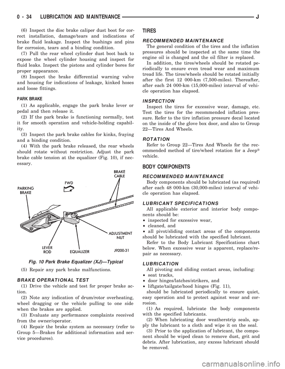
brake cable tension at the equalizer (Fig. 10), if nec-
essary.
(5) Repair any park brake malfunctions.
BRAKE OPERATIONAL TEST
(1) Drive the vehicle and test for proper brake ac-
tion.
(2) Note any indication of drum/rotor overheating,
wheel dragging or the vehicle pulling to one side
when the brakes are applied.
(3) Evaluate any performance complaints received
from the owner/operator.
(4) Repair the brake system as necessary (refer to
Group 5ÐBrakes for additional information and ser-
vice procedures).
TIRES
RECOMMENDED MAINTENANCE
The general condition of the tires and the inflation
pressures should be inspected at the same time the
engine oil is changed and the oil filter is replaced.
In addition, the tires/wheels should be rotated pe-
riodically to ensure even tread wear and maximum
tread life. The tires/wheels should be rotated initially
after the first 12 000-km (7,500-miles). Thereafter,
after each 24 000-km (15,000-miles) interval of vehi-
cle operation has elapsed.
INSPECTION
Inspect the tires for excessive wear, damage, etc.
Test the tires for the recommended inflation pres-
sure. Refer to the tire inflation pressure decal located
on the inside of the glove box door, and also to Group
22ÐTires And Wheels.
ROTATION
Refer to Group 22ÐTires And Wheels for the rec-
ommended method of tire/wheel rotation for a Jeept
vehicle.
BODY COMPONENTS
RECOMMENDED MAINTENANCE
Body components should be lubricated (as required)
after each 48 000-km (30,000-miles) interval of vehi-
cle operation has elapsed.
LUBRICANT SPECIFICATIONS
All applicable exterior and interior body compo-
nents should be:
²inspected for excessive wear,
²cleaned, and
²all pivot/sliding contact areas of the components
should be lubricated with the specified lubricant.
Refer to the Body Lubricant Specifications chart
below. When excessive wear is apparent, replace/re-
pair as necessary.
LUBRICATION
All pivoting and sliding contact areas, including:
²seat tracks,
²door hinges/latches/strikers, and
²liftgate/tailgate/hood hinges (Fig. 11),
should be lubricated periodically to ensure quiet,
easy operation and to protect against wear and cor-
rosion.
(1) As required, lubricate the body components
with the specified lubricants.
(2) When lubricating door weatherstrip seals, ap-
ply the lubricant to a cloth and wipe it on the seal.
(3) Prior to the application of lubricant, the compo-
nent should be wiped clean to remove dust, grit and
debris. After lubrication, any excess lubricant should
be removed.
Fig. 10 Park Brake Equalizer (XJ)ÐTypical
0 - 34 LUBRICATION AND MAINTENANCEJ
Page 275 of 1784
BATTERY TEST PROCEDURES
INDEX
page page
Battery Charging.......................... 5
Battery Diagnostics Chart................... 7
Battery Load Test......................... 4
Battery Open Circuit Voltage Test............. 3Battery Testing General Information........... 3
General Information........................ 2
Hydrometer Test.......................... 3
Specifications............................ 8
GENERAL INFORMATION
The battery stores, stabilizes, and produces electri-
cal current. A battery must be able to accept a
charge and produce high-amperage current output
over an extended period. A chemical reaction occurs
between the sulfuric acid solution (electrolyte) and
the lead +/þ plates in each cell of the battery. As
the battery discharges, the plates collect the acid
from the electrolyte. When the charging system
charges the battery, water is converted to sulfuric
acid in the battery. The amount of acid (specific
gravity) in the electrolyte can be measured with a
hydrometer. The battery is vented to release gases
that are created when the battery is being charged.
The battery top,posts, and terminals should be cleaned when other
underhood maintenance is performed.
WARNING: DO NOT ATTEMPT TO ASSIST BOOST,
CHARGE, OR TEST BATTERY WHEN ELECTRO-
LYTE LEVEL IS BELOW THE TOP OF THE PLATES.
PERSONAL INJURY MAY OCCUR.
When the electrolyte level is below the top of the
plates distilled water should be added. The battery
must be completely charged. The top, posts, and ter-
minals should be properly cleaned before diagnostic
procedures are performed. See Group 8B - Battery/
Starter/Generator Service, for additional information.
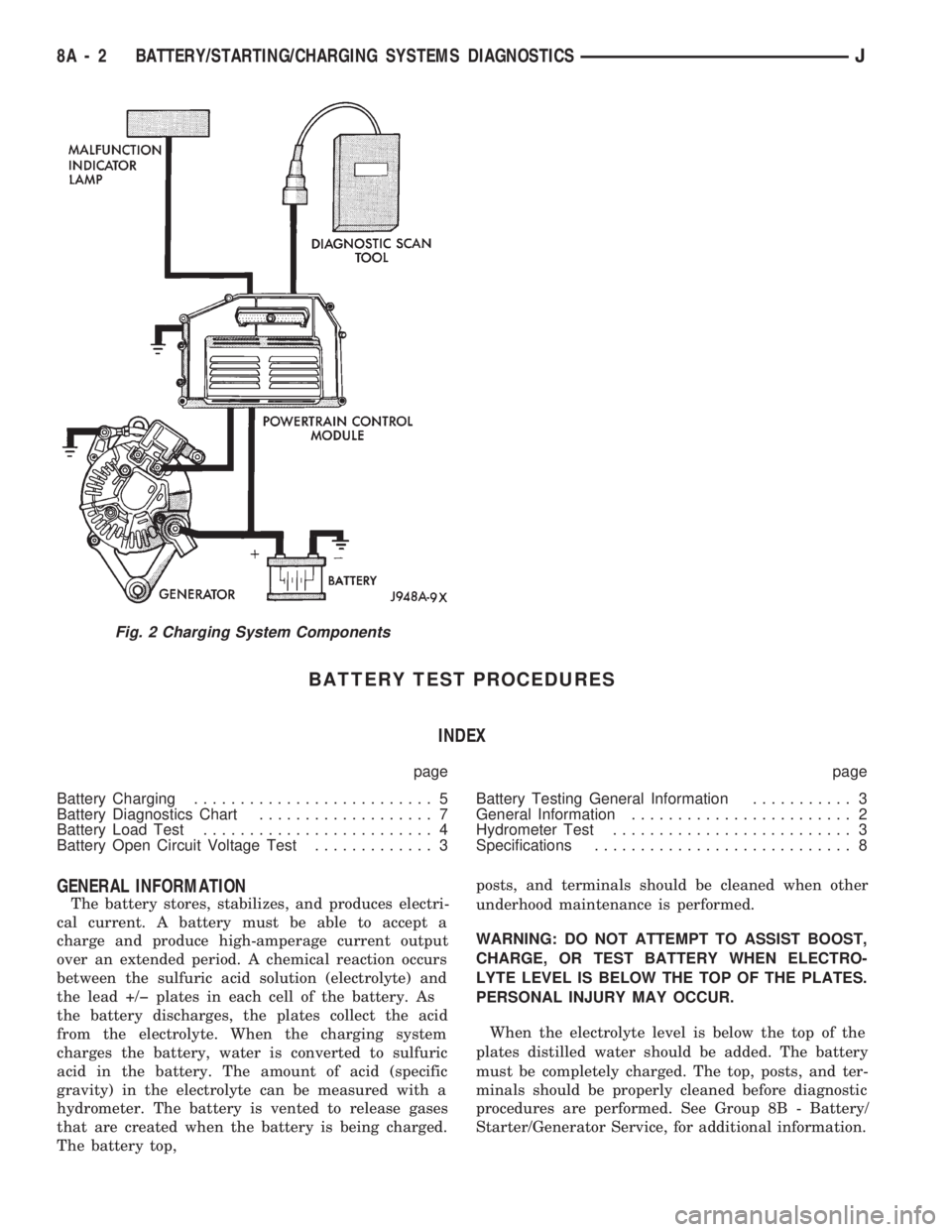
Fig. 2 Charging System Components
8A - 2 BATTERY/STARTING/CHARGING SYSTEMS DIAGNOSTICSJ
Page 855 of 1784
(2) Install the upper inner retainer and bushing on
the top of the damper.
(3) Position the upper damper bracket over the
damper and install the stud nut and bolts.
(4) Tighten the stud nut to 23 Nzm (17 ft. lbs.)
torque. Tighten the bracket bolts to 61 Nzm (45 ft.
lbs.) torque.
(5) Install the bushing, upper outer retainer and
damper nut.
(6) Install the bushing, lower outer retainer and
damper nut.
(7) Tighten the upper and lower damper nuts.
(8) Connect negative cable to battery.
ENGINE ASSEMBLYÐXJ VEHICLES
REMOVAL
(1) Disconnect the battery cables. Remove the bat-
tery.
(2) Mark the hinge locations on the hood panel for
alignment reference during installation. Remove the
engine compartment lamp. Remove the hood.
WARNING: THE COOLANT IN A RECENTLY OPER-
ATED ENGINE IS HOT AND PRESSURIZED. USE
CARE TO PREVENT SCALDING BY HOT COOLANT.
CAREFULLY RELEASE THE PRESSURE BEFORE
REMOVING THE RADIATOR DRAIN COCK AND
CAP.(3) Remove the radiator drain cock and radiator
cap to drain the coolant. DO NOT waste usable cool-
ant. If the solution is clean, drain the coolant into a
clean container for reuse.
(4) Remove the lower radiator hose.
(5) Remove the upper radiator hose and coolant re-
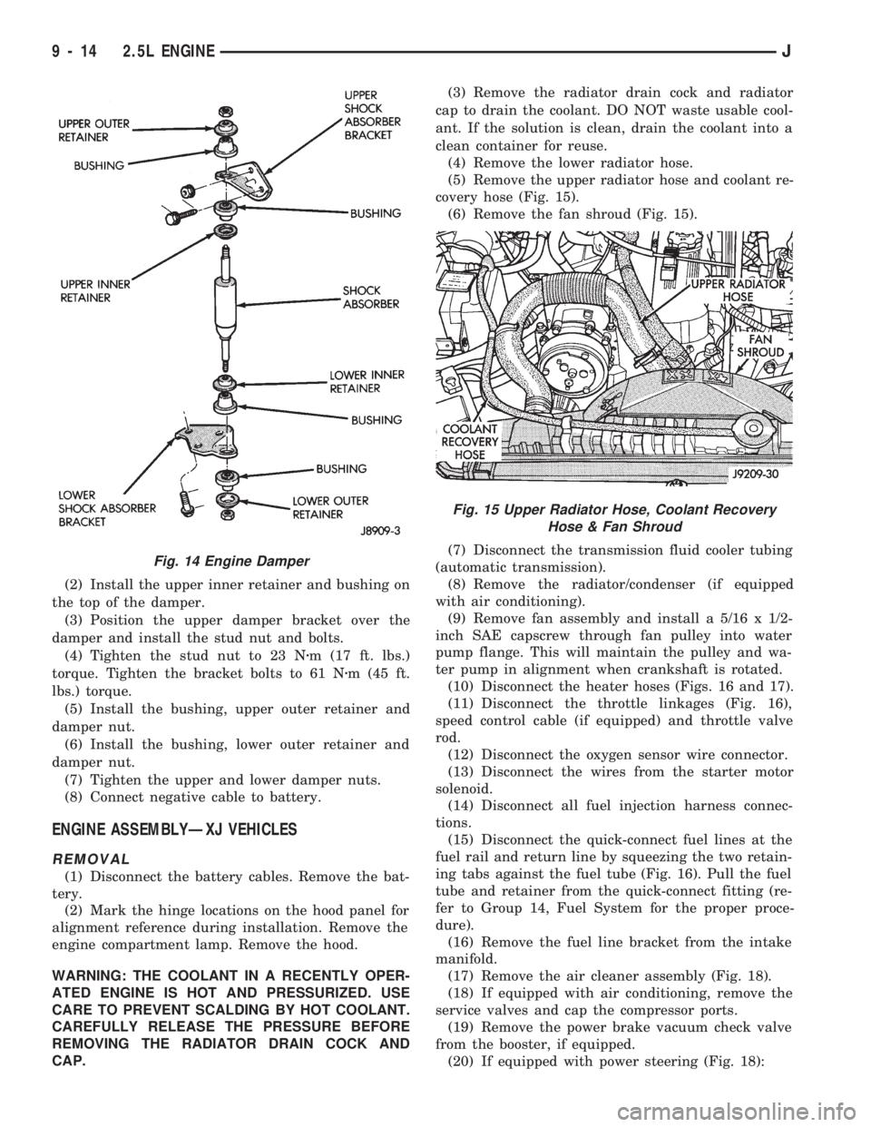
covery hose (Fig. 15).
(6) Remove the fan shroud (Fig. 15).
(7) Disconnect the transmission fluid cooler tubing
(automatic transmission).
(8) Remove the radiator/condenser (if equipped
with air conditioning).
(9) Remove fan assembly and install a 5/16 x 1/2-
inch SAE capscrew through fan pulley into water
pump flange. This will maintain the pulley and wa-
ter pump in alignment when crankshaft is rotated.
(10) Disconnect the heater hoses (Figs. 16 and 17).
(11) Disconnect the throttle linkages (Fig. 16),
speed control cable (if equipped) and throttle valve
rod.
(12) Disconnect the oxygen sensor wire connector.
(13) Disconnect the wires from the starter motor
solenoid.
(14) Disconnect all fuel injection harness connec-
tions.
(15) Disconnect the quick-connect fuel lines at the
fuel rail and return line by squeezing the two retain-
ing tabs against the fuel tube (Fig. 16). Pull the fuel
tube and retainer from the quick-connect fitting (re-
fer to Group 14, Fuel System for the proper proce-
dure).
(16) Remove the fuel line bracket from the intake
manifold.
(17) Remove the air cleaner assembly (Fig. 18).
(18) If equipped with air conditioning, remove the
service valves and cap the compressor ports.
(19) Remove the power brake vacuum check valve
from the booster, if equipped.
(20) If equipped with power steering (Fig. 18):
Fig. 14 Engine Damper
Fig. 15 Upper Radiator Hose, Coolant Recovery
Hose & Fan Shroud
9 - 14 2.5L ENGINEJ
Page 857 of 1784
(a) Align the transmission torque converter
housing with the engine.
(b) Loosely install the converter housing lower
bolts and install the next higher bolt and nut on
each side.
(c) Tighten all 4 bolts finger-tight.
(5) Install the engine support cushions (if re-
moved).
(6) Lower the engine and engine support cushions
onto the engine compartment brackets.
(7) Remove the engine lifting device.
(8) Raise the vehicle.
(9) If equipped with an automatic transmission:
(a) Install the converter-to-drive plate bolts. En-
sure the installation reference marks are aligned.
Tighten the bolts to 54 Nzm (40 ft. lbs.) torque.
(b) Install the converter-housing access cover.
(c) Install the exhaust pipe support.
(10) Install the remaining converter or flywheel
housing bolts.
(11) Install the starter motor and connect the ca-
ble. Tighten the bolts to 45 Nzm (33 ft. lbs.) torque.
(12) Tighten the engine support cushing through-
bolt nuts.
(13) Install the remaining flywheel/converter hous-
ing bolts. Tighten the bolts to 38 Nzm (28 ft. lbs.)
torque.
(14) Connect the exhaust pipe to the manifold.
(15) Install the oil filter.
(16) Lower the vehicle.
(17) Connect the coolant hoses and tighten the
clamps.
(18) If equipped with power steering:
(a) Remove the protective caps
(b) Connect the hoses to the fittings at the steer-
ing gear. Tighten the nut to 52 Nzm (38 ft. lbs.)
torque.
(c) Fill the pump reservoir with fluid.
(19) Remove the pulley-to-water pump flange
alignment capscrew and install the fan and spacer or
Tempatrol fan assembly.
(20) Install the fan shroud and radiator/condenser
(if equipped with air conditioning).
(21) Connect the radiator hoses.
(22) Connect the automatic transmission fluid
cooler pipes, if equipped.
(23) Connect the oxygen sensor wire connector.
(24) Connect the throttle valve rod and retainer.
Connect the throttle cable and install the rod. Install
the throttle valve rod spring.
(25) Connect the speed control cable, if equipped.
(26) Connect the fuel supply and return lines to
the throttle body.
(27) Connect all the vacuum hoses and wire con-
nectors.
(28) Connect the service valves to the A/C com-
pressor ports, if equipped with air conditioning.(29) Fill the power steering reservoir.
(30) Connect the battery cables.
(31) Install the hood.
(32) Install the air cleaner.
(33) Start the engine and inspect for leaks.
(34) Fill the cooling system.
(35) Stop the engine and check the fluid levels.
Add fluid, as required.
ENGINE ASSEMBLYÐYJ VEHICLES
REMOVAL
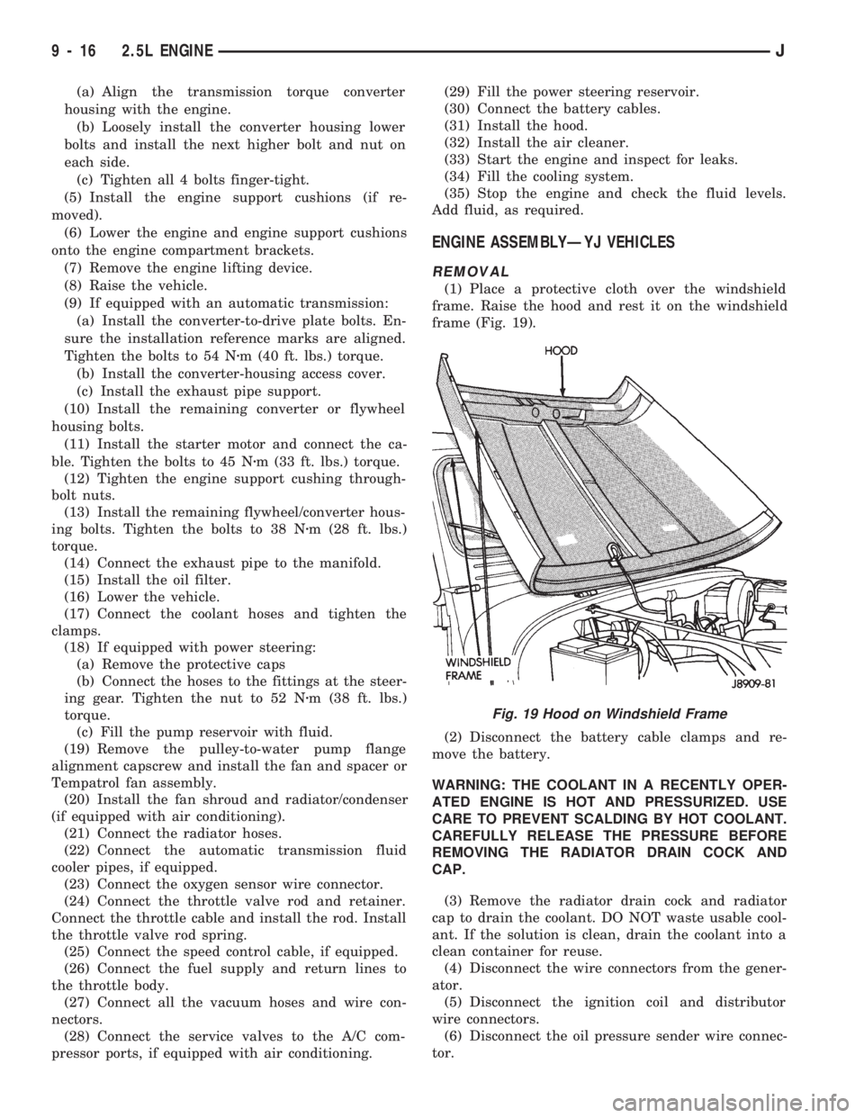
(1) Place a protective cloth over the windshield
frame. Raise the hood and rest it on the windshield
frame (Fig. 19).
(2) Disconnect the battery cable clamps and re-
move the battery.
WARNING: THE COOLANT IN A RECENTLY OPER-
ATED ENGINE IS HOT AND PRESSURIZED. USE
CARE TO PREVENT SCALDING BY HOT COOLANT.
CAREFULLY RELEASE THE PRESSURE BEFORE
REMOVING THE RADIATOR DRAIN COCK AND
CAP.
(3) Remove the radiator drain cock and radiator
cap to drain the coolant. DO NOT waste usable cool-
ant. If the solution is clean, drain the coolant into a
clean container for reuse.
(4) Disconnect the wire connectors from the gener-
ator.
(5) Disconnect the ignition coil and distributor
wire connectors.
(6) Disconnect the oil pressure sender wire connec-
tor.
Fig. 19 Hood on Windshield Frame
9 - 16 2.5L ENGINEJ
Page 895 of 1784
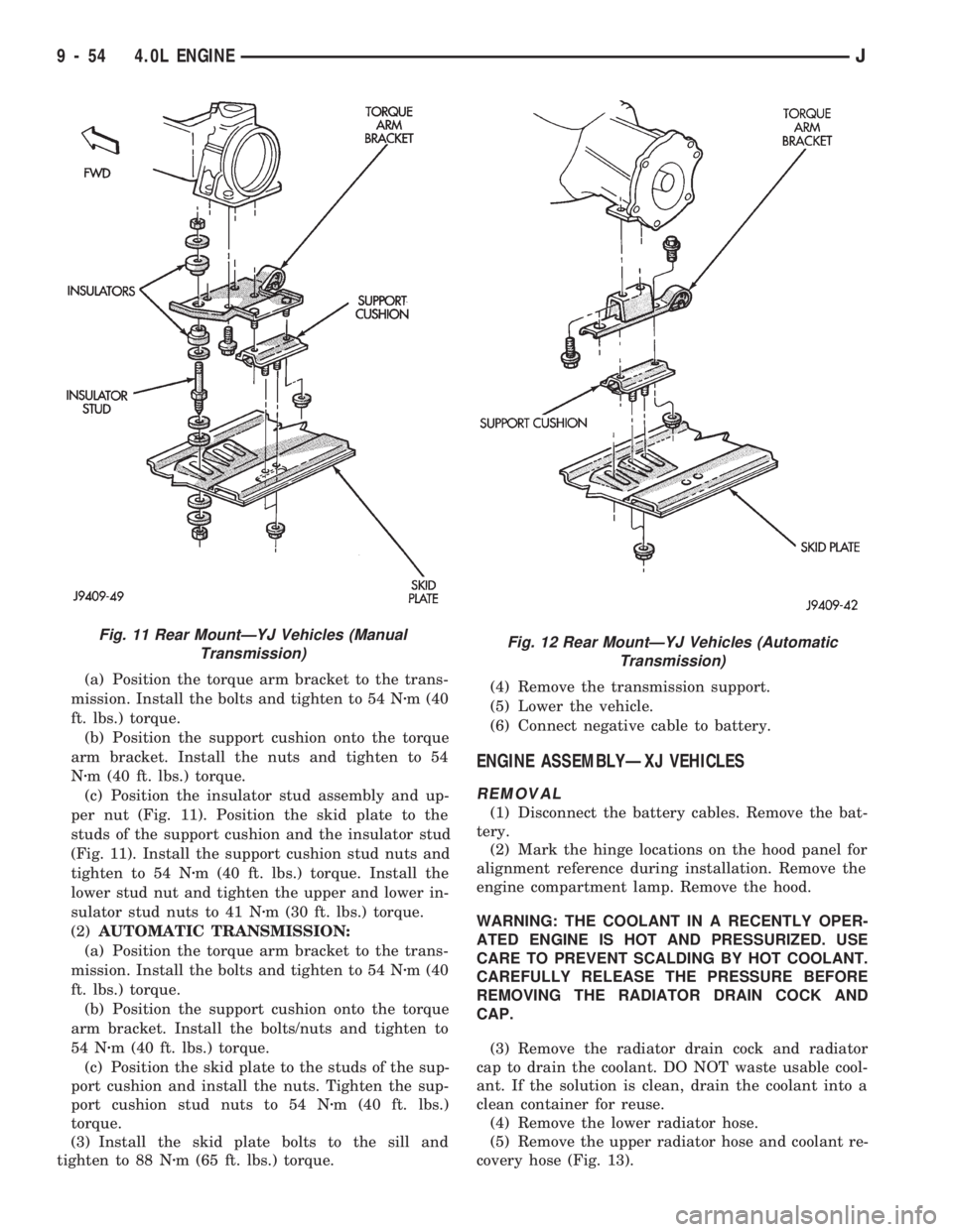
(a) Position the torque arm bracket to the trans-
mission. Install the bolts and tighten to 54 Nzm (40
ft. lbs.) torque.
(b) Position the support cushion onto the torque
arm bracket. Install the nuts and tighten to 54
Nzm (40 ft. lbs.) torque.
(c) Position the insulator stud assembly and up-
per nut (Fig. 11). Position the skid plate to the
studs of the support cushion and the insulator stud
(Fig. 11). Install the support cushion stud nuts and
tighten to 54 Nzm (40 ft. lbs.) torque. Install the
lower stud nut and tighten the upper and lower in-
sulator stud nuts to 41 Nzm (30 ft. lbs.) torque.
(2)AUTOMATIC TRANSMISSION:
(a) Position the torque arm bracket to the trans-
mission. Install the bolts and tighten to 54 Nzm (40
ft. lbs.) torque.
(b) Position the support cushion onto the torque
arm bracket. Install the bolts/nuts and tighten to
54 Nzm (40 ft. lbs.) torque.
(c) Position the skid plate to the studs of the sup-
port cushion and install the nuts. Tighten the sup-
port cushion stud nuts to 54 Nzm (40 ft. lbs.)
torque.
(3) Install the skid plate bolts to the sill and
tighten to 88 Nzm (65 ft. lbs.) torque.(4) Remove the transmission support.
(5) Lower the vehicle.
(6) Connect negative cable to battery.
ENGINE ASSEMBLYÐXJ VEHICLES
REMOVAL
(1) Disconnect the battery cables. Remove the bat-
tery.
(2) Mark the hinge locations on the hood panel for
alignment reference during installation. Remove the
engine compartment lamp. Remove the hood.
WARNING: THE COOLANT IN A RECENTLY OPER-
ATED ENGINE IS HOT AND PRESSURIZED. USE
CARE TO PREVENT SCALDING BY HOT COOLANT.
CAREFULLY RELEASE THE PRESSURE BEFORE
REMOVING THE RADIATOR DRAIN COCK AND
CAP.
(3) Remove the radiator drain cock and radiator
cap to drain the coolant. DO NOT waste usable cool-
ant. If the solution is clean, drain the coolant into a
clean container for reuse.
(4) Remove the lower radiator hose.
(5) Remove the upper radiator hose and coolant re-
covery hose (Fig. 13).
Fig. 11 Rear MountÐYJ Vehicles (Manual
Transmission)Fig. 12 Rear MountÐYJ Vehicles (Automatic
Transmission)
9 - 54 4.0L ENGINEJ
Page 898 of 1784
(28) Connect the heater hoses at the engine ther-
mostat housing and water pump.
(29) Install the fan assembly to the idler pulley.
(30) Install the radiator or radiator/condenser (if
equipped with A/C).
(31) Connect the service valves to the A/C com-
pressor ports, if equipped with A/C.
(32) Charge the air conditioner system.
(33) Connect radiator fan switch wire.
(34) Connect the radiator hoses and automatic
transmission fluid cooler pipes, if equipped.
(35) Install the fan shroud, electric cooling fan and
radiator/condenser (if equipped with A/C).
(36) Install upper radiator support.
(37) Connect the upper radiator hose and tighten
the clamp.
(38) Connect the lower radiator hose and tighten
the clamp.
(39) Fill the cooling system with reusable coolant
and/or new coolant.
(40) Align the hood to the scribe marks. Install the
hood.
(41) Connect the vacuum harness connector.
(a) Firmly push the connectors together ensuring
that the retaining tabs are engaged.
(b) Insert the vacuum connector assembly into
the retaining bracket on the intake manifold.
(42) Install the air cleaner assembly.
(43) Install the battery and connect the battery ca-
ble.
WARNING: USE EXTREME CAUTION WHEN THE
ENGINE IS OPERATING. DO NOT STAND IN A DI-
RECT LINE WITH THE FAN. DO NOT PUT YOUR
HANDS NEAR THE PULLEYS, BELTS OR FAN. DO
NOT WEAR LOOSE CLOTHING.
(44) Start the engine, inspect for leaks and correct
the fluid levels, as necessary.
ENGINE ASSEMBLYÐYJ VEHICLES
REMOVAL
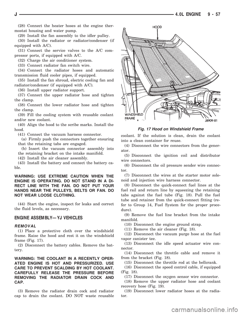
(1) Place a protective cloth over the windshield
frame. Raise the hood and rest it on the windshield
frame (Fig. 17).
(2) Disconnect the battery cables. Remove the bat-
tery.
WARNING: THE COOLANT IN A RECENTLY OPER-
ATED ENGINE IS HOT AND PRESSURIZED. USE
CARE TO PREVENT SCALDING BY HOT COOLANT.
CAREFULLY RELEASE THE PRESSURE BEFORE
REMOVING THE RADIATOR DRAIN COCK AND
CAP.
(3) Remove the radiator drain cock and radiator
cap to drain the coolant. DO NOT waste reusablecoolant. If the solution is clean, drain the coolant
into a clean container for reuse.
(4) Disconnect the wire connectors from the gener-
ator.
(5) Disconnect the ignition coil and distributor
wire connectors.
(6) Disconnect the oil pressure sender wire connec-
tor.
(7) Disconnect the wires at the starter motor sole-
noid and injection wire harness connector.
(8) Disconnect the quick-connect fuel lines at the
fuel rail and return line by squeezing the retaining
tabs against the fuel tube (Fig. 18). Pull the fuel
tube and retainer from the quick-connect fitting (re-
fer to Group 14, Fuel System for the proper proce-
dure).
(9) Remove the fuel line bracket from the intake
manifold.
(10) Disconnect the engine ground strap.
(11) Remove the air cleaner (Fig. 18).
(12) Disconnect the vacuum purge hose at the fuel
vapor canister tee.
(13) Disconnect the idle speed actuator wire con-
nector.
(14) Disconnect the throttle cable and remove it
from the bracket (Fig. 18).
(15) Disconnect the throttle rod at the bellcrank.
(16) Disconnect the speed control cable, if equipped
(Fig. 18).
(17) Disconnect the oxygen sensor wire connector.
(18) Remove the upper radiator hose and coolant
recovery hose (Fig. 19).
(19) Disconnect lower radiator hoses at the radia-
tor.
Fig. 17 Hood on Windshield Frame
J4.0L ENGINE 9 - 57
Page 1296 of 1784
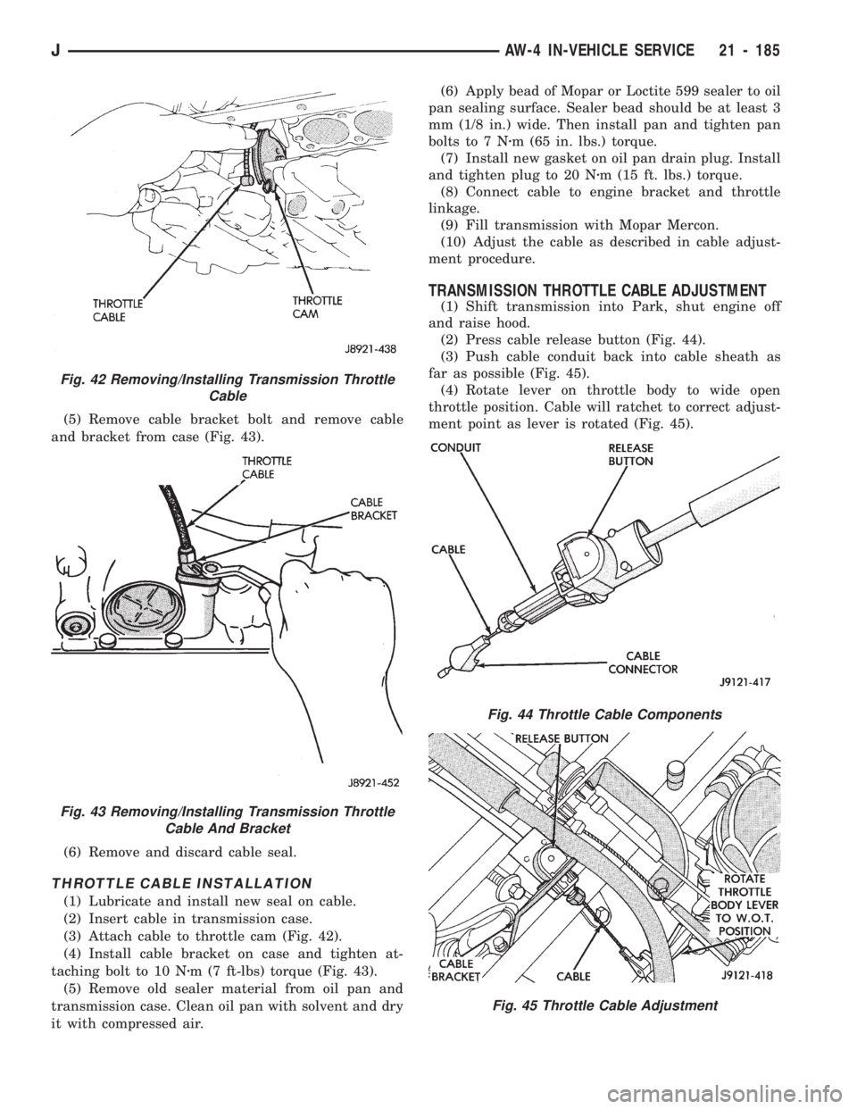
(5) Remove cable bracket bolt and remove cable
and bracket from case (Fig. 43).
(6) Remove and discard cable seal.
THROTTLE CABLE INSTALLATION
(1) Lubricate and install new seal on cable.
(2) Insert cable in transmission case.
(3) Attach cable to throttle cam (Fig. 42).
(4) Install cable bracket on case and tighten at-
taching bolt to 10 Nzm (7 ft-lbs) torque (Fig. 43).
(5) Remove old sealer material from oil pan and
transmission case. Clean oil pan with solvent and dry
it with compressed air.(6) Apply bead of Mopar or Loctite 599 sealer to oil
pan sealing surface. Sealer bead should be at least 3
mm (1/8 in.) wide. Then install pan and tighten pan
bolts to 7 Nzm (65 in. lbs.) torque.
(7) Install new gasket on oil pan drain plug. Install
and tighten plug to 20 Nzm (15 ft. lbs.) torque.
(8) Connect cable to engine bracket and throttle
linkage.
(9) Fill transmission with Mopar Mercon.
(10) Adjust the cable as described in cable adjust-
ment procedure.
TRANSMISSION THROTTLE CABLE ADJUSTMENT
(1) Shift transmission into Park, shut engine off
and raise hood.
(2) Press cable release button (Fig. 44).
(3) Push cable conduit back into cable sheath as
far as possible (Fig. 45).
(4) Rotate lever on throttle body to wide open
throttle position. Cable will ratchet to correct adjust-
ment point as lever is rotated (Fig. 45).
Fig. 42 Removing/Installing Transmission Throttle
Cable
Fig. 43 Removing/Installing Transmission Throttle
Cable And Bracket
Fig. 44 Throttle Cable Components
Fig. 45 Throttle Cable Adjustment
JAW-4 IN-VEHICLE SERVICE 21 - 185
Page 1461 of 1784
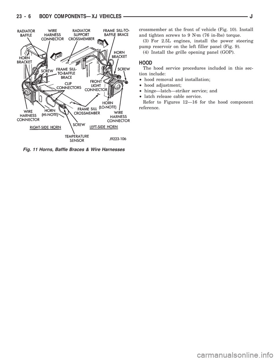
crossmember at the front of vehicle (Fig. 10). Install
and tighten screws to 9 Nzm (76 in-lbs) torque.
(3) For 2.5L engines, install the power steering
pump reservoir on the left filler panel (Fig. 9).
(4) Install the grille opening panel (GOP).
HOOD
The hood service procedures included in this sec-
tion include:
²hood removal and installation;
²hood adjustment;
²hingeÐlatchÐstriker service; and
²latch release cable service.
Refer to Figures 12Ð16 for the hood component
reference.
Fig. 11 Horns, Baffle Braces & Wire Harnesses
23 - 6 BODY COMPONENTSÐXJ VEHICLESJ