1994 JEEP CHEROKEE tow bar
[x] Cancel search: tow barPage 10 of 1784
²if the vehicle is damaged, secure the loose and pro-
truding parts;
²always use a safety chain system that is indepen-
dent of the lifting and towing equipment;
²do not allow any of the towing equipment to con-
tact the disabled vehicle's fuel tank;
²do not allow anyone to be under the disabled vehi-
cle while it is lifted by the towing equipment;
²do not allow passengers to ride in a vehicle being
towed;
²always observe all state and local laws involving
warning signals, night illumination, speed, etc.
²do not attempt a towing operation that could jeop-
ardize the safety of the operator, bystanders or other
motorists;
²do not exceed a towing speed of 48 km/h (30 mph);
²avoid towing distances of more than 24 km (15
miles) whenever possible; and
²do not attach tow chains or a tow sling to a
bumper, the steering linkage, the universal joints,
the constant velocity (CV) joints, or a drive shaft.
CLEARANCES AND RAMP ANGLE
SURFACE CLEARANCE
The end of the disabled vehicle that is attached to
the tow vehicle should be lifted a minimum of 10 cm
or four inches off the surface. Inspect to ensure that
the opposite end of the disabled vehicle has clearance
from the surface.
RAMP ANGLEÐFLAT-BED TOWING
If a vehicle with flat-bed towing equipment is used,
the approach ramp angle should not exceed 15 de-
grees.
SLING-TYPE, FRONT-END TOWING
XJ VEHICLES
Use the following guidelines when the tow vehicle
is attached to the front end of a disabled vehicle.
(1) Always tow with the front wheels lifted off the
surface and turned all the way to the right.
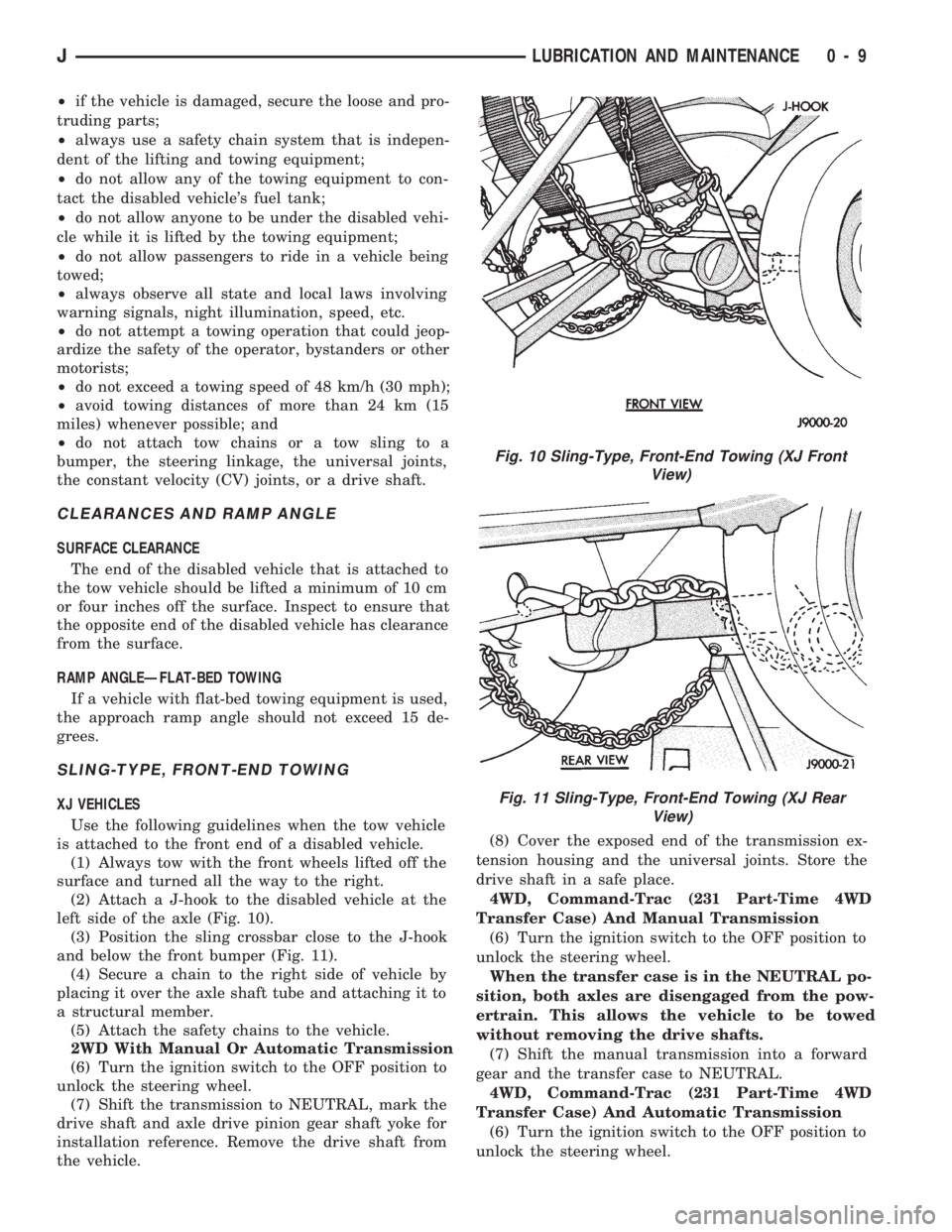
(2) Attach a J-hook to the disabled vehicle at the
left side of the axle (Fig. 10).
(3) Position the sling crossbar close to the J-hook
and below the front bumper (Fig. 11).
(4) Secure a chain to the right side of vehicle by
placing it over the axle shaft tube and attaching it to
a structural member.
(5) Attach the safety chains to the vehicle.
2WD With Manual Or Automatic Transmission
(6) Turn the ignition switch to the OFF position to
unlock the steering wheel.
(7) Shift the transmission to NEUTRAL, mark the
drive shaft and axle drive pinion gear shaft yoke for
installation reference. Remove the drive shaft from
the vehicle.(8) Cover the exposed end of the transmission ex-
tension housing and the universal joints. Store the
drive shaft in a safe place.
4WD, Command-Trac (231 Part-Time 4WD
Transfer Case) And Manual Transmission
(6) Turn the ignition switch to the OFF position to
unlock the steering wheel.
When the transfer case is in the NEUTRAL po-
sition, both axles are disengaged from the pow-
ertrain. This allows the vehicle to be towed
without removing the drive shafts.
(7) Shift the manual transmission into a forward
gear and the transfer case to NEUTRAL.
4WD, Command-Trac (231 Part-Time 4WD
Transfer Case) And Automatic Transmission
(6) Turn the ignition switch to the OFF position to
unlock the steering wheel.
Fig. 10 Sling-Type, Front-End Towing (XJ Front
View)
Fig. 11 Sling-Type, Front-End Towing (XJ Rear
View)
JLUBRICATION AND MAINTENANCE 0 - 9
Page 11 of 1784
When the transfer case is in the NEUTRAL po-
sition, both axles are disengaged from the pow-
ertrain. This allows the vehicle to be towed
without removing the drive shafts.
(7) Shift the automatic transmission to PARK and
the transfer case to NEUTRAL.
4WD, Selec-Trac (242 Full-Time 4WD Transfer
Case) And Automatic Transmission
(6) Turn the ignition switch to the OFF position to
unlock the steering wheel.
When the transfer case is in the NEUTRAL po-
sition, both axles are disengaged from the pow-
ertrain. This allows the vehicle to be towed
without removing the drive shafts.
(7) Shift the automatic transmission to PARK and
the transfer case to NEUTRAL.
YJ VEHICLES
Use the following guidelines when the tow vehicle
is attached to the front of a disabled vehicle.
(1) Always tow with the front wheels lifted off the
surface and turned all the way to the right.
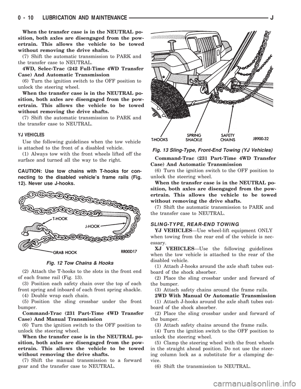
CAUTION: Use tow chains with T-hooks for con-
necting to the disabled vehicle's frame rails (Fig.
12). Never use J-hooks.
(2) Attach the T-hooks to the slots in the front end
of each frame rail (Fig. 13).
(3) Position each safety chain over the top of each
front spring and inboard of each front spring shackle.
(4) Double wrap each chain.
(5) Position the sling crossbar under the front
bumper.
Command-Trac (231 Part-Time 4WD Transfer
Case) And Manual Transmission
(6) Turn the ignition switch to the OFF position to
unlock the steering wheel.
When the transfer case is in the NEUTRAL po-
sition, both axles are disengaged from the pow-
ertrain. This allows the vehicle to be towed
without removing the drive shafts.
(7) Shift the manual transmission to a forward
gear and the transfer case to NEUTRAL.Command-Trac (231 Part-Time 4WD Transfer
Case) And Automatic Transmission
(6) Turn the ignition switch to the OFF position to
unlock the steering wheel.
When the transfer case is in the NEUTRAL po-
sition, both axles are disengaged from the pow-
ertrain. This allows the vehicle to be towed
without removing the drive shafts.
(7) Shift the automatic transmission to PARK and
the transfer case to NEUTRAL.
SLING-TYPE, REAR-END TOWING
YJ VEHICLESÐUse wheel-lift equipment ONLY
when towing from the rear end of the vehicle is nec-
essary.
XJ VEHICLESÐUse the following guidelines
when the tow vehicle is attached to the rear of the
disabled vehicle.
(1) Attach J-hooks around the axle shaft tubes out-
board of the shock absorber.
(2) Place the sling crossbar under and forward of
the bumper.
(3) Attach safety chains around the frame rails.
2WD With Manual Or Automatic Transmission
(1) Attach J-hooks around the axle shaft tubes out-
board of the shock absorber.
(2) Place the sling crossbar under and forward of
the bumper.
(3) Attach safety chains around the frame rails.
(4) Turn the ignition switch to the OFF position to
unlock the steering wheel.
(5) Clamp the steering wheel with the front wheels
in the straight ahead position. Do not use the steer-
ing column lock as a substitute for a clamping de-
vice.
(6) Shift the transmission to NEUTRAL.
Fig. 12 Tow Chains & Hooks
Fig. 13 Sling-Type, Front-End Towing (YJ Vehicles)
0 - 10 LUBRICATION AND MAINTENANCEJ
Page 12 of 1784
4WD, Command-Trac (231 Part-Time 4WD
Transfer Case) And Manual Transmission
(1) Attach J-hooks around the axle shaft tubes out-
board of the shock absorber.
(2) Place the sling crossbar under and forward of
the bumper.
(3) Attach safety chains around the frame rails.
(4) Turn the ignition switch to the OFF position to
unlock the steering column.
(5) Clamp the steering wheel with the front wheels
in the straight ahead position. Do not use the steer-
ing column lock as a substitute for a clamping de-
vice.
When the transfer case is in the NEUTRAL po-
sition, both axles are disengaged from the pow-
ertrain. This allows the vehicle to be towed
without removing the drive shafts.
(6) Shift the transmission to a forward gear and
the transfer case to NEUTRAL.
4WD, Command-Trac (231 Part-Time 4WD
Transfer Case) And Automatic Transmission
(1) Attach J-hooks around the axle shaft tubes out-
board of the shock absorber.
(2) Place the sling crossbar under and forward of
the bumper.
(3) Attach safety chains around the frame rails.
(4) Turn the ignition switch to the OFF position to
unlock the steering column.
(5) Clamp the steering wheel with the front wheels
in the straight ahead position. Do not use the steer-
ing column lock as a substitute for a clamping de-
vice.
When the transfer case is in the NEUTRAL po-
sition, both axles are disengaged from the pow-
ertrain. This allows the vehicle to be towed
without removing the drive shafts.
(6) Shift the transmission to PARK and the trans-
fer case to NEUTRAL.
4WD, Selec-Trac (242 Full-Time 4WD Transfer
Case) And Automatic Transmission
(1) Attach J-hooks around the axle shaft tubes out-
board of the shock absorber.
(2) Place the sling crossbar under and forward of
the bumper.
(3) Attach safety chains around the frame rails.
(4) Turn the ignition switch to the OFF position to
unlock the steering column.
(5) Clamp the steering wheel with the front wheels
in the straight ahead position. Do not use the steer-
ing column lock as a substitute for a clamping de-
vice.
When the transfer case is in the NEUTRAL po-
sition, both axles are disengaged from the pow-
ertrain. This allows the vehicle to be towed
without removing the drive shafts.
(6) Shift the transmission to PARK and the trans-
fer case to NEUTRAL.TOWING WHEN IGNITION KEYS ARE NOT
AVAILABLE
VEHICLE DOORS UNLOCKED
2WD Vehicles
Either one of two methods can be used:
²tow the vehicle with the drive shaft removed (refer
to Sling-Type, Front-End Towing); or
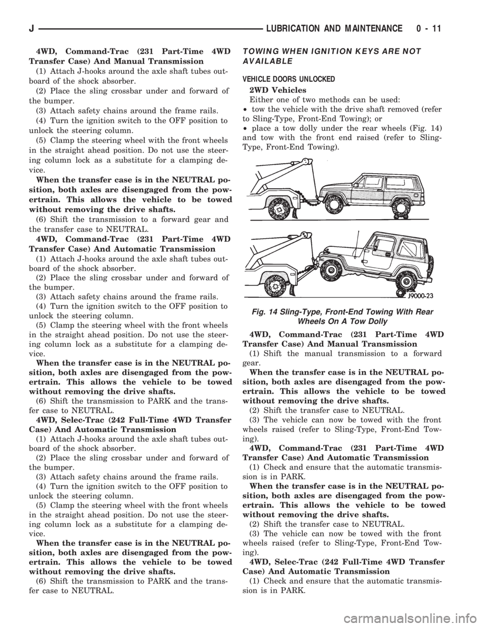
²place a tow dolly under the rear wheels (Fig. 14)
and tow with the front end raised (refer to Sling-
Type, Front-End Towing).
4WD, Command-Trac (231 Part-Time 4WD
Transfer Case) And Manual Transmission
(1) Shift the manual transmission to a forward
gear.
When the transfer case is in the NEUTRAL po-
sition, both axles are disengaged from the pow-
ertrain. This allows the vehicle to be towed
without removing the drive shafts.
(2) Shift the transfer case to NEUTRAL.
(3) The vehicle can now be towed with the front
wheels raised (refer to Sling-Type, Front-End Tow-
ing).
4WD, Command-Trac (231 Part-Time 4WD
Transfer Case) And Automatic Transmission
(1) Check and ensure that the automatic transmis-
sion is in PARK.
When the transfer case is in the NEUTRAL po-
sition, both axles are disengaged from the pow-
ertrain. This allows the vehicle to be towed
without removing the drive shafts.
(2) Shift the transfer case to NEUTRAL.
(3) The vehicle can now be towed with the front
wheels raised (refer to Sling-Type, Front-End Tow-
ing).
4WD, Selec-Trac (242 Full-Time 4WD Transfer
Case) And Automatic Transmission
(1) Check and ensure that the automatic transmis-
sion is in PARK.
Fig. 14 Sling-Type, Front-End Towing With Rear
Wheels On A Tow Dolly
JLUBRICATION AND MAINTENANCE 0 - 11
Page 51 of 1784
STABILIZER BAR
REMOVAL
(1) Raise and support the vehicle.
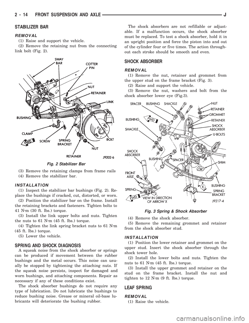
(2) Remove the retaining nut from the connecting
link bolt (Fig. 2).
(3) Remove the retaining clamps from frame rails
(4) Remove the stabilizer bar.
INSTALLATION
(1) Inspect the stabilizer bar bushings (Fig. 2). Re-
place the bushings if cracked, cut, distorted, or worn.
(2) Position the stabilizer bar on the frame. Install
the retaining brackets and fasteners. Tighten bolts to
41 Nzm (30 ft. lbs.) torque.
(3) Install the link upper bolts and nuts. Tighten
the nuts to 61 Nzm (45 ft. lbs.) torque.
(4) Tighten the link spring bracket nuts to 61 Nzm
(45 ft. lbs.) torque.
(5) Lower the vehicle.
SPRING AND SHOCK DIAGNOSIS
A squeak noise from the shock absorber or springs
can be produced if movement between the rubber
bushings and the metal occurs. This noise can usu-
ally be stopped by tightening the attaching nuts. If
the squeak noise persists, inspect for damaged and
worn bushings, and attaching components. Repair as
necessary if any of these conditions exist.
The shock absorber bushings do not require any
type of lubrication. Do not lubricate the bushings to
reduce bushing noise. Grease or mineral oil-base lu-
bricants will deteriorate the bushing rubber.The shock absorbers are not refillable or adjust-
able. If a malfunction occurs, the shock absorber
must be replaced. To test a shock absorber, hold it in
an upright position and force the piston into and out
of the cylinder four or five times. The action through-
out each stroke should be smooth and even.
SHOCK ABSORBER
REMOVAL
(1) Remove the nut, retainer and grommet from
the upper stud on the frame bracket (Fig. 3).
(2) Raise and support the vehicle.
(3) Remove the nut, washers and bolt from the
shock absorber lower eye (Fig.3).
(4) Remove the shock absorber.
(5) Remove the remaining grommet and retainer
from the shock absorber stud.
INSTALLATION
(1) Position the lower retainer and grommet on the
upper stud. Insert the shock absorber through the
shock tower hole.
(2) Install the lower bolts and nuts. Tighten the
nuts to 61 Nzm (45 ft. lbs.) torque.
(3) Install the upper grommet and retainer on the
stud on the frame bracket. Install the nut and
tighten to 12 Nzm (9 ft. lbs.) torque.
LEAF SPRING
REMOVAL
(1) Raise the vehicle.
Fig. 2 Stabilizer Bar
Fig. 3 Spring & Shock Absorber
2 - 14 FRONT SUSPENSION AND AXLEJ
Page 344 of 1784
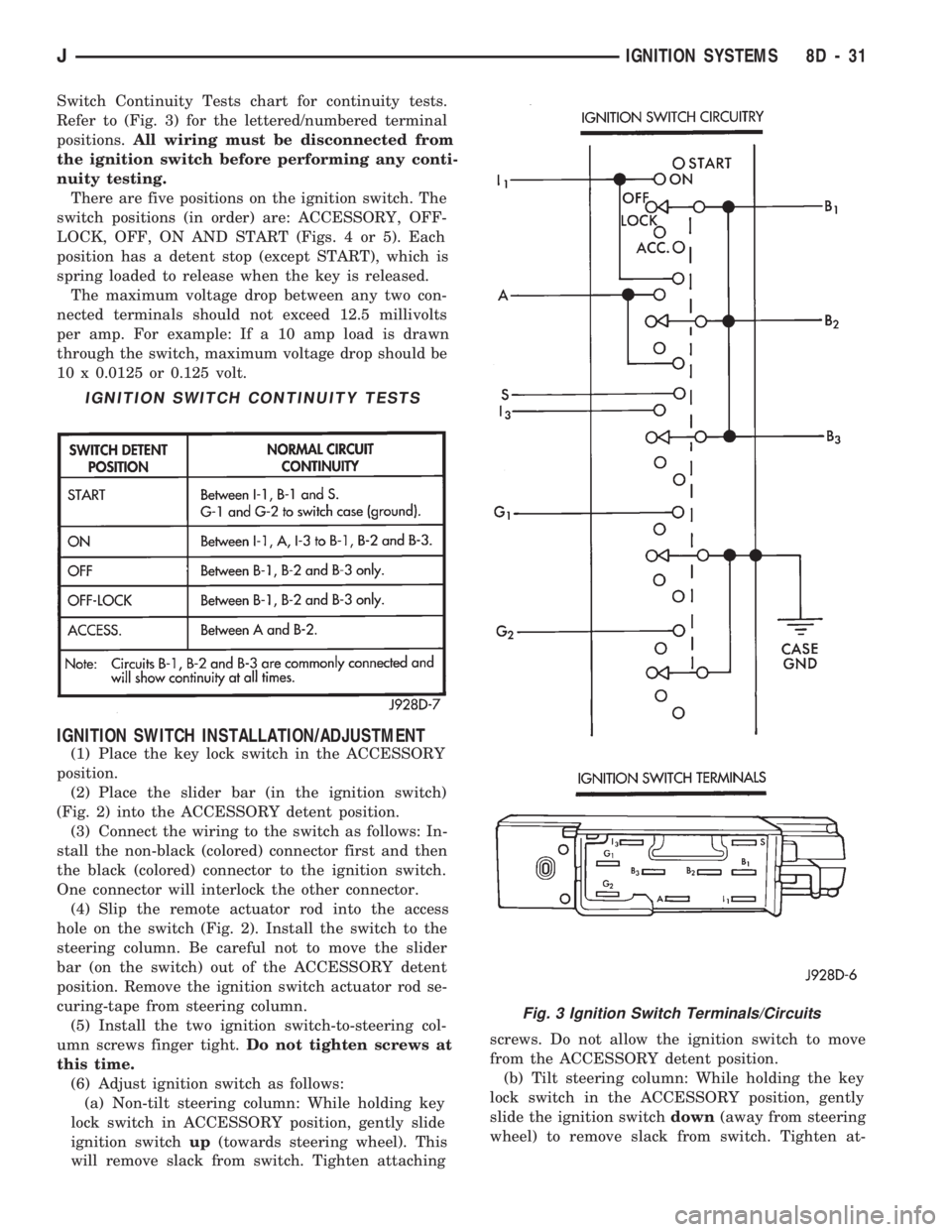
Switch Continuity Tests chart for continuity tests.
Refer to (Fig. 3) for the lettered/numbered terminal
positions.All wiring must be disconnected from
the ignition switch before performing any conti-
nuity testing.
There are five positions on the ignition switch. The
switch positions (in order) are: ACCESSORY, OFF-
LOCK, OFF, ON AND START (Figs. 4 or 5). Each
position has a detent stop (except START), which is
spring loaded to release when the key is released.
The maximum voltage drop between any two con-
nected terminals should not exceed 12.5 millivolts
per amp. For example: If a 10 amp load is drawn
through the switch, maximum voltage drop should be
10 x 0.0125 or 0.125 volt.
IGNITION SWITCH INSTALLATION/ADJUSTMENT
(1) Place the key lock switch in the ACCESSORY
position.
(2) Place the slider bar (in the ignition switch)
(Fig. 2) into the ACCESSORY detent position.
(3) Connect the wiring to the switch as follows: In-
stall the non-black (colored) connector first and then
the black (colored) connector to the ignition switch.
One connector will interlock the other connector.
(4) Slip the remote actuator rod into the access
hole on the switch (Fig. 2). Install the switch to the
steering column. Be careful not to move the slider
bar (on the switch) out of the ACCESSORY detent
position. Remove the ignition switch actuator rod se-
curing-tape from steering column.
(5) Install the two ignition switch-to-steering col-
umn screws finger tight.Do not tighten screws at
this time.
(6) Adjust ignition switch as follows:
(a) Non-tilt steering column: While holding key
lock switch in ACCESSORY position, gently slide
ignition switchup(towards steering wheel). This
will remove slack from switch. Tighten attachingscrews. Do not allow the ignition switch to move
from the ACCESSORY detent position.
(b) Tilt steering column: While holding the key
lock switch in the ACCESSORY position, gently
slide the ignition switchdown(away from steering
wheel) to remove slack from switch. Tighten at-
IGNITION SWITCH CONTINUITY TESTS
Fig. 3 Ignition Switch Terminals/Circuits
JIGNITION SYSTEMS 8D - 31
Page 845 of 1784

CONNECTING ROD BEARING CLEARANCE
Engine connecting rod bearing clearances can be
determined by use of Plastigage, or equivalent. The
following is the recommended procedures for the use
of Plastigage:
(1) Remove oil film from surface to be checked.
Plastigage is soluble in oil.
(2) Place a piece of Plastigage across the entire
width of the bearing cap shell (Fig. 2). Position the
Plastigage approximately 6.35 mm (1/4 inch) off cen-
ter and away from the oil holes. In addition, suspect
areas can be checked by placing the Plastigage in the
suspect area.
(3) The crankshaft must be turned until the con-
necting rod to be checked starts moving toward the
top of the engine. Only then should the rod cap with
Plastigage in place be assembled. Tighten the rod
cap nut to 45 Nzm (33 ft. lbs.) torque.DO NOT ro-
tate the crankshaft or the Plastigage may be
smeared, giving inaccurate results.
(4) Remove the bearing cap and compare the width
of the flattened Plastigage with the scale provided on
the package (Fig. 3). Plastigage generally comes in 2
scales (one scale is in inches and the other is a met-
ric scale). Locate the band closest to the same width.
This band shows the amount of clearance. Differ-
ences in readings between the ends indicate the
amount of taper present. Record all readings taken
(refer to Engine Specifications).
(5) Plastigage is available in a variety of clearance
ranges. The 0.025-0.076 mm (0.001-0.003 inch) range
is usually the most appropriate for checking engine
bearing clearances.
REPAIR DAMAGED OR WORN THREADS
Damaged or worn threads can be repaired. Essen-
tially, this repair consists of:
²Drilling out worn or damaged threads.
²Tapping the hole with a special Heli-Coil Tap, or
equivalent.
²Installing an insert into the tapped hole.
This brings the hole back to its original thread size.
CAUTION: Be sure that the tapped holes maintain
the original center line.Heli-Coil tools and inserts are readily available
from automotive parts jobbers.
SERVICE ENGINE ASSEMBLY (SHORT BLOCK)
A service replacement engine assembly (short
block) may be installed whenever the original cylin-
der block is defective or damaged beyond repair. It
consists of the cylinder block, crankshaft, piston and
rod assemblies. If needed, the camshaft must be pro-
cured separately and installed before the engine is
installed in the vehicle.
A short block is identified with the letter ``S'' stamped
on the same machined surface where the build date
code is stamped for complete engine assemblies.
Installation includes the transfer of components
from the defective or damaged original engine. Fol-
low the appropriate procedures for cleaning, inspec-
tion and torque tightening.
HYDROSTATIC LOCK
When an engine is suspected of hydrostatic lock
(regardless of what caused the problem), follow the
steps below.
(1) Perform the Fuel Pressure Release Procedure
(refer to Group 14, Fuel System).
(2) Disconnect the negative cable from the battery.
(3) Inspect air cleaner, induction system and in-
take manifold to ensure system is dry and clear of
foreign material.
(4) Place a shop towel around the spark plugs to
catch any fluid that may possibly be under pressure in
the cylinder head. Remove the plugs from the engine.
CAUTION: DO NOT use the starter motor to rotate
the crankshaft. Severe damage could occur.
(5) With all spark plugs removed, rotate the crank-
shaft using a breaker bar and socket.
(6) Identify the fluid in the cylinders (i.e. coolant,
fuel, oil, etc.).
(7) Make sure all fluid has been removed from the
cylinders.
(8) Repair engine or components as necessary to
prevent this problem from occurring again.
(9) Squirt engine oil into the cylinders to lubricate
the walls. This will prevent damage on restart.
(10) Install new spark plugs. Tighten the spark
plugs to 37 Nzm (27 ft. lbs.) torque.
(11) Drain engine oil. Remove and discard the oil
filter.
(12) Install the drain plug. Tighten the plug to 34
Nzm (25 ft. lbs.) torque.
(13) Install a new oil filter.
(14) Fill engine crankcase with the specified
amount and grade of oil (refer to Group 0, Lubrica-
tion and Maintenance).
(15) Connect the negative cable to the battery.
(16) Start the engine and check for any leaks.
Fig. 3 Clearance Measurement
9 - 4 ENGINESJ
Page 1626 of 1784
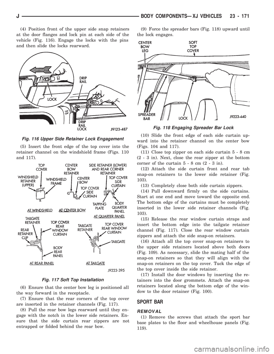
(4) Position front of the upper side snap retainers
at the door flanges and lock pin at each side of the
vehicle (Fig. 116). Engage the locks with the pins
and then slide the locks rearward.
(5) Insert the front edge of the top cover into the
retainer channel on the windshield frame (Figs. 110
and 117).
(6) Ensure that the center bow leg is positioned all
the way forward in the receptacle.
(7) Ensure that the rear corners of the top cover
are inserted in the retainer channels (Fig. 117).
(8) Pull the rear bow legs rearward until they en-
gage with the notch in the lower side retainers. En-
sure that the side curtain rear zippers are not
entrapped or folded behind the rear bow.(9) Force the spreader bars (Fig. 118) upward until
the lock engages.
(10) Slide the front edge of each side curtain up-
ward into the retainer channel on the center bow
(Figs. 104 and 117).
(11) Close top zipper on each side curtain5-8cm
(2 - 3 in). Next, close the rear zipper at the bottom
corner of the curtain5-8cm(2-3in).
(12) Attach the side curtain front and rear tab
snap-on retainers to the lower side retainer (Fig.
103).
(13) Completely close both side curtain zippers.
(14) Pull downward firmly on the side curtains.
Start at one end and move toward the opposite end.
The bottom edge of the curtains must be completely
inserted in the lower side retainer channels (Fig.
103).
(15) Release the rear window curtain straps and
insert the bottom edge into the tailgate retainer
channel (Fig. 117). Close the rear window curtain
zippers and attach the side snap-on retainers.
(16) Attach all the top cover snap-on retainers to
the upper side retainers located above both doors
(Fig. 109). As necessary, slide the mating half of the
snap-on retainers so that they will align with the
snap-on retainers on the top cover. Tuck the edge of
the top cover inside the side retainer.
(17) Install the door windows by inserting the re-
tainers into the door grommets. Attach the snap-on
retainers located along the bottom edge of the win-
dow to the door retainer (Fig. 100).
SPORT BAR
REMOVAL
(1) Remove the screws that attach the sport bar
base plates to the floor and wheelhouse panels (Fig.
119).
Fig. 116 Upper Side Retainer Lock Engagement
Fig. 117 Soft Top Installation
Fig. 118 Engaging Spreader Bar Lock
JBODY COMPONENTSÐXJ VEHICLES 23 - 171
Page 1767 of 1784
TEMPERATURE SENSOR TEST, ENGINE
COOLANT; FUEL SYSTEM..............14-43
TEMPERATURE SENSOR TEST, ENGINE
COOLANT; IGNITION SYSTEMS..........8D-12
TEMPERATURE SENSOR TEST, INTAKE
AIR ...............................14-43
TEMPERATURE SENSOR TEST, INTAKE
MANIFOLD AIR......................8D-14
TENSION, BELT.......................8B-10
TENSION, DRIVE BELT...............7-33,7-38
TENSIONÐRIGHT HAND DRIVE
(RHD),BELT..........................7-34
TENSION SPECIFICATIONS, BELT...........7-34
TENSIONER REPLACEMENT (XJ), PARKING
BRAKE CABLE........................5-61
TENSIONERÐXJ MODELS, AUTOMATIC
BELT ...............................7-36
TERMINAL ASSEMBLY REPLACEMENT,
CONNECTOR.........................8W-5
TERMINAL REPLACEMENT...............8W-5
TEST, A/C PERFORMANCE................24-8
TEST, ACTUATOR MOTOR STALL...........8P-6
TEST, AIR PRESSURE...................21-73
TEST, ANALYZING THE ROAD.............21-70
TEST, BATTERY LOAD...................8A-4
TEST, BATTERY OPEN CIRCUIT VOLTAGE....8A-3
TEST, CAMSHAFT POSITION SENSOR;
FUEL SYSTEM.......................14-43
TEST, CAMSHAFT POSITION SENSOR;
IGNITION SYSTEMS...................8D-8
TEST, CONVERTER STALL...............21-72
TEST, CRANKSHAFT POSITION SENSOR;
FUEL SYSTEM.......................14-44
TEST, CRANKSHAFT POSITION SENSOR;
IGNITION SYSTEMS...................8D-9
TEST, CYLINDER COMBUSTION
PRESSURE LEAKAGE...................9-6
TEST, CYLINDER COMBUSTION
PRESSURE LEAKAGE DIAGNOSIS..........9-6
TEST, CYLINDER COMPRESSION PRESSURE . . 9-5
TEST, ENGINE COOLANT TEMPERATURE
SENSOR......................8D-12,14-43
TEST, EXTENDED IDLE SWITCH...........14-45
TEST, FUEL PRESSURE LEAK DOWN........14-7
TEST, FUEL PUMP CAPACITY..............14-7
TEST, FUEL SYSTEM PRESSURE......14-5,14-48
TEST, HYDRAULIC PRESSURE......21-71,21-168
TEST, HYDROMETER....................8A-3
TEST, IDLE AIR CONTROL MOTOR........14-46
TEST, INJECTOR.......................14-48
TEST, INTAKE AIR TEMPERATURE SENSOR . . 8D-14,
14-43
TEST, MANIFOLD ABSOLUTE PRESSURE
(MAP) SENSOR.................8D-14,14-44
TEST, MANUAL SHIFTING...............21-168
TEST, MASTER CYLINDER/POWER
BOOSTER............................5-11
TEST, OXYGEN SENSOR (O2S)
HEATING ELEMENT...................14-45
TEST, POWER BOOSTER CHECK VALVE......5-11
TEST, POWER BOOSTER VACUUM..........5-12
TEST PROCEDURES, BATTERY............8A-2
TEST PROCEDURES ON VEHICLE,
ENGINE STARTER MOTOR..............8A-9
TEST PROCEDURES ON VEHICLE,
GENERATOR........................8A-14
TEST, PUMP PRESSURE.................19-3
TEST, REAR WINDOW DEFOGGER GRID.....8N-1
TEST, REFRIGERANT LEAK................24-8
TEST, ROAD; TRANSMISSION AND
TRANSFER CASE.....................21-70
TEST, ROAD; VEHICLE SPEED CONTROL
SYSTEM............................8H-5
TEST SPECIFICATIONS, 30RH/32RH
PRESSURE........................21-323
TEST, SPEED CONTROL SWITCH (TURN
SIGNAL LEVER)......................8H-7
TEST, STARTER MOTOR RELAY...........14-48
TEST, STARTING SYSTEM COLD
CRANKING...........................8A-9
TEST, STOP LAMP SPEED CONTROL
SWITCH
............................8H-7
TEST, THROTTLE POSITION SENSOR
......8D-18
TEST, THROTTLE POSITION SENSOR
(TPS)
..............................14-45
TEST, TIME LAG
......................21-169TEST, TORQUE CONVERTER CLUTCH
RELAY.............................14-45
TEST, TORQUE CONVERTER STALL.......21-169
TEST, VACUUM SUPPLY.................8H-7
TEST, VEHICLE SPEED SENSOR......8H-5,14-45
TESTING, AUTOMATIC SHUTDOWN
(ASD) RELAY........................14-43
TESTING COOLING SYSTEM FOR LEAKS.....7-18
TESTING, FUEL PUMP RELAY............14-44
TESTING GENERAL INFORMATION,
BATTERY............................8A-3
TESTING, IGNITION SWITCH.............8D-30
TESTING, POWER MIRROR SWITCH........8T-2
TESTING, REAR WIPER/WASHER
SWITCH.......................8K-7,8K-14
TESTING, SWITCH; POWER SEATS.........8R-2
TESTING, SWITCH; POWER WINDOWS......8S-5
TESTING, SWITCH; REAR WINDOW
DEFOGGER..........................8N-2
TESTING, TRANSMISSION COOLER FLOW . . 21-106
TESTING, WIPER SWITCH...............8K-19
TESTS - (VOLTAGE DROP METHOD),
STARTER FEED CIRCUIT................8A-9
TESTS, ANTENNA.......................8F-9
TESTS AT POWERTRAIN CONTROL
MODULE, ELECTRICAL.................8H-6
TESTS AT SERVO, ELECTRICAL............8H-5
TESTS, COMPRESSOR VALVE PLATEÐ
LEAK...............................24-8
TESTS, IGNITION SWITCH CONTINUITY....8D-31
TESTS, OXYGEN SENSOR...............8D-19
TESTS, STARTER CONTROL CIRCUIT......8A-11
TESTS, VEHICLE SPEED CONTROL
SYSTEM............................8H-5
TESTS, WATER PUMP....................7-9
THERMOMETER AND SENSOR SYSTEM
REPAIR PROCEDURES.................8C-6
THERMOSTAT..........................7-13
THERMOSTAT, TEMPERATURE CONTROL . . . 24-35
THICKNESS, AW-4 CLUTCH DISC AND
PLATE ............................21-325
THICKNESS, DISC BRAKE ROTOR..........5-31
THICKNESS VARIATION, DISC BRAKE
ROTOR.............................5-31
THIRD GEAR (CONVERTER CLUTCH
ENGAGED), HYDRAULIC FLOW IN.......21-90
THIRD GEAR, HYDRAULIC FLOW IN D
RANGE.............................21-89
THREAD NOTATIONÐSAE AND METRIC . . INTRO.-9
THREADS, REPAIR DAMAGED OR WORN.....9-4
THROTTLE 3-2 DOWNSHIFT, HYDRAULIC
FLOW DURING FULL..................21-92
THROTTLE 3-2 DOWNSHIFT, HYDRAULIC
FLOW DURING PART..................21-91
THROTTLE BODY; FUEL SYSTEM.....14-29,14-59
THROTTLE CABLE.....................14-16
THROTTLE CABLE, ACCELERATOR PEDAL . . 14-16,
14-54
THROTTLE CABLE ADJUSTMENT,
TRANSMISSION.....................21-185
THROTTLE CABLE ADJUSTMENT,
TRANSMISSION......................21-98
THROTTLE CABLE REPLACEMENT,
TRANSMISSION.....................21-184
THROTTLE POSITION SENSOR............8D-6
THROTTLE POSITION SENSOR TEST.......8D-18
THROTTLE POSITION SENSOR (TPS);
FUEL SYSTEM.......................14-59
THROTTLE POSITION SENSOR (TPS);
IGNITION SYSTEMS..................8D-29
THROTTLE POSITION SENSOR (TPS)
SERVICE..........................21-184
THROTTLE POSITION SENSOR (TPS)
TEST..............................14-45
THROTTLE POSITION SENSOR (TPS)Ð
PCM INPUT.........................14-23
THROTTLE VALVE CABLE ADJUSTMENT,
TRANSMISSION......................21-70
TIE ROD ........................19-14,19-17
TIGHTENING, WHEEL NUT............5-32,5-37
TILT STEERING COLUMN................19-59
TIME LAG TEST
......................21-169
TIMING CASE COVER
................9-27,9-67
TIMING CASE COVER OIL SEAL
REPLACEMENT
...................9-26,9-67
TIMING CHAIN AND SPROCKETS
......9-28,9-68TIMING, IGNITION.....................8D-14
TIMING, VALVE.....................9-26,9-66
TIPS, TRANSMISSION ASSEMBLY........21-146
TIRE AND WHEEL BALANCE..............22-6
TIRE AND WHEEL RUNOUT...............22-8
TIRE CARRIER, EXTERNAL SPARE/WHEEL . 23-172
TIRE INFLATION PRESSURE LABEL.....INTRO.-3
TIRE INFLATION PRESSURES.............22-2
TIRE NOISE OR VIBRATION...............22-4
TIRE WEAR PATTERNS..................22-4
TIRES; LUBRICATION AND MAINTENANCE....0-34
TIRES................................22-1
TIRES, CLEANING OF....................22-2
TIRES, REPLACEMENT...................22-2
TIRE/WHEEL HOLDDOWN AND FLOOR
BRACKETS.........................23-128
TOOL, DRB SCAN; COOLING SYSTEM........7-5
TOOL, DRB SCAN; EMISSION CONTROL
SYSTEMS...........................25-2
TOOL, DRB SCAN; FUEL SYSTEM.........14-51
TOOL, DRB SCAN; IGNITION SYSTEMS.....8D-10
TOP REPAIR, HARD...................23-165
TOP ROOF VENT......................23-165
TOP SERVICE............23-164,23-166,23-167
TORQUE; COOLING SYSTEM..............7-39
TORQUE; FUEL SYSTEM................14-62
TORQUE; IGNITION SYSTEMS............8D-33
TORQUE, COLLISION DAMAGE............13-1
TORQUE CONVERSION..............INTRO.-10
TORQUE CONVERTER; TRANSMISSION
AND TRANSFER CASE...........21-66,21-158
TORQUE CONVERTER CLUTCH RELAY......14-60
TORQUE CONVERTER CLUTCH RELAY
TEST..............................14-45
TORQUE CONVERTER CLUTCH RELAYÐ
PCM OUTPUT.......................14-27
TORQUE CONVERTER INSTALLATION,
TRANSMISSION.....................21-190
TORQUE CONVERTER REMOVAL,
TRANSMISSION.....................21-189
TORQUE CONVERTER STALL TEST.......21-169
TORQUE CONVERTER STATOR CLUTCH
INSPECTION.......................21-189
TORQUE SPECIFICATIONS, 30RH/32RH....21-323
TORQUE SPECIFICATIONSÐ AX 15
MANUAL TRANSMISSION.............21-320
TORQUE SPECIFICATIONSÐACCESSORIES . 23-208
TORQUE SPECIFICATIONS, AW-4
.........21-331
TORQUE SPECIFICATIONS, BATTERY
.......8B-10
TORQUE SPECIFICATIONS; BATTERY/
STARTER/GENERATOR SERVICE
.........8B-12
TORQUE SPECIFICATIONS, BRAKE
..........5-67
TORQUE SPECIFICATIONS; CLUTCH
........6-17
TORQUE SPECIFICATIONS; ELECTRICAL
.....8A-8
TORQUE SPECIFICATIONS; ENGINES
....9-49,9-89
TORQUE SPECIFICATIONS; EXHAUST
SYSTEM AND INTAKE MANIFOLD
........11-10
TORQUE SPECIFICATIONS; FRONT
SUSPENSION AND AXLE
................2-47
TORQUE SPECIFICATIONS; HEATING AND
AIR CONDITIONING
...................24-45
TORQUE SPECIFICATIONS; HORNS
.........8G-3
TORQUE SPECIFICATIONS;
INTRODUCTION
...................INTRO.-8
TORQUE SPECIFICATIONS, NP231/NP242
. . 21-331
TORQUE SPECIFICATIONS; PROPELLER
SHAFTS
............................16-14
TORQUE SPECIFICATIONS; REAR
SUSPENSION AND AXLES
...............3-50
TORQUE SPECIFICATIONS, STARTER
MOTOR
............................8B-11
TORQUE SPECIFICATIONS; STEERING
......19-73
TORQUE SPECIFICATIONS XJ
.............8K-7
TORQUE SPECIFICATIONSÐXJ VEHICLES
. . 23-207
TORQUE VALUES, STANDARD
.........INTRO.-9
TOW HOOKÐXJ VEHICLES, REAR
.........23-87
TOW HOOKS
..........................13-14
TOW HOOKS, FRONT
....................13-5
TOWING, JUMP STARTING, HOISTING
.......0-7
TOWING RECOMMENDATIONS
..............0-8
TRACK BAR
....................2-10,2-13,3-6
TRACKS, BUCKET SEAT PLATFORM
.......23-105
TRAC-LOK DIFFERENTIAL
................3-44
JINDEX23
Description Group-Page Description Group-Page Description Group-Page