1994 JEEP CHEROKEE oil viscosity
[x] Cancel search: oil viscosityPage 3 of 1784
ROUTINE SERVICE
The following routine vehicle service is highly rec-
ommended on a monthly basis.
TIRESÐInspect the tires for unusual wear/damage
and determine if the inflation pressure is acceptable
for the vehicle load.
BATTERYÐInspect and clean the terminals.
Tighten the terminals, if necessary.
FLUIDSÐDetermine if the coolant, brake fluid,
power steering, automatic transmission, and clutch
fluid level are acceptable. Add fluid, if necessary.
LIGHTS/ELECTRICALÐTest all the electrically
operated systems in the vehicle for proper operation.
It is also recommended that the engine oil level
and the windshield washer fluid level be deter-
mined (and corrected) during each fuel fill-up.
FUEL REQUIREMENTS
All Jeeptengines require the use of unleaded gas-
oline. In addition, the fuel must have a minimum oc-
tane rating of 87.
CAUTION: UNLEADED FUEL ONLY must be used in
vehicles equipped with a catalyst emission control
system. All vehicles have reminders printed on the
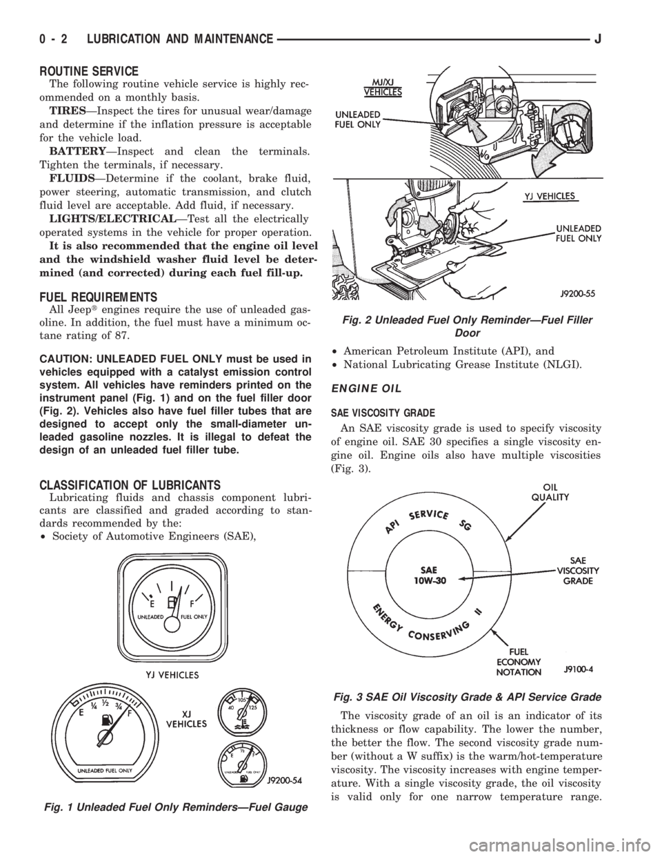
instrument panel (Fig. 1) and on the fuel filler door
(Fig. 2). Vehicles also have fuel filler tubes that are
designed to accept only the small-diameter un-
leaded gasoline nozzles. It is illegal to defeat the
design of an unleaded fuel filler tube.
CLASSIFICATION OF LUBRICANTS
Lubricating fluids and chassis component lubri-
cants are classified and graded according to stan-
dards recommended by the:
²Society of Automotive Engineers (SAE),²American Petroleum Institute (API), and
²National Lubricating Grease Institute (NLGI).
ENGINE OIL
SAE VISCOSITY GRADE
An SAE viscosity grade is used to specify viscosity
of engine oil. SAE 30 specifies a single viscosity en-
gine oil. Engine oils also have multiple viscosities
(Fig. 3).
The viscosity grade of an oil is an indicator of its
thickness or flow capability. The lower the number,
the better the flow. The second viscosity grade num-
ber (without a W suffix) is the warm/hot-temperature
viscosity. The viscosity increases with engine temper-
ature. With a single viscosity grade, the oil viscosity
is valid only for one narrow temperature range.
Fig. 1 Unleaded Fuel Only RemindersÐFuel Gauge
Fig. 2 Unleaded Fuel Only ReminderÐFuel Filler
Door
Fig. 3 SAE Oil Viscosity Grade & API Service Grade
0 - 2 LUBRICATION AND MAINTENANCEJ
Page 4 of 1784
Above that temperature range the viscosity will de-
crease, and below that range the viscosity will in-
crease.
An engine oil with an SAE 5W-30 viscosity grade
provides good flow capability for fast cold weather
engine starts. The viscosity will then increase with
engine temperature to provide good high-tempera-
ture engine lubrication.
API SERVICE GRADE
The API Service Grade specifies the type of engine/
operating conditions for which the oil is intended.
The API Service Grade specifications also apply to
energy conserving engine oils (Fig. 3). The API cer-
tification mark is also used indicating that the oil is
certified to meet the most critical requirements es-
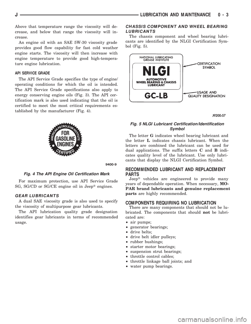
tablished by the manufacturer (Fig. 4).
For maximum protection, use API Service Grade
SG, SG/CD or SG/CE engine oil in Jeeptengines.
GEAR LUBRICANTS
A dual SAE viscosity grade is also used to specify
the viscosity of multipurpose gear lubricants.
The API lubrication quality grade designation
identifies gear lubricants in terms of recommended
usage.
CHASSIS COMPONENT AND WHEEL BEARING
LUBRICANTS
The chassis component and wheel bearing lubri-
cants are identified by the NLGI Certification Sym-
bol (Fig. 5).
The letterGindicates wheel bearing lubricant and
the letterLindicates chassis lubricant. When the
letters are combined the lubricant can be used for
dual applications. The suffix lettersCandBindi-
cates quality level of the lubricant. Use only lubri-
cants that display the NLGI Certification Symbol.
RECOMMENDED LUBRICANT AND REPLACEMENT
PARTS
Jeeptvehicles are engineered to provide many
years of dependable operation. When necessary,MO-
PAR brand lubricants and genuine replacement
partsare highly recommended.
COMPONENTS REQUIRING NO LUBRICATION
There are many components that should not be lu-
bricated. The components that shouldnotbe lubri-
cated are:
²air pumps;
²generator bearings;
²drive belts;
²drive belt idler pulleys;
²rubber bushings;
²starter motor bearings;
²suspension strut bearings;
²throttle control cables;
²throttle linkage ball joints; and
²water pump bearings.
Fig. 4 The API Engine Oil Certification Mark
Fig. 5 NLGI Lubricant Certification/Identification
Symbol
JLUBRICATION AND MAINTENANCE 0 - 3
Page 14 of 1784

ENGINE MAINTENANCE
INDEX
page page
Accessory Drive Belt...................... 20
Air-Conditioner Compressor/Hoses/Fittings...... 21
Battery................................ 18
Cooling System.......................... 16
Crankcase Ventilation System............... 17
Engine Air Cleaner Filter Element............ 16
Engine Break-In......................... 13
Engine Oil.............................. 13Engine Oil Change and Filter Replacement..... 15
Engine Oil Filter......................... 14
Engine Supports......................... 20
Exhaust System......................... 20
Fuel Usage StatementÐGas Engines......... 17
Ignition Cables, Distributor Cap and Rotor...... 18
Rubber and Plastic Ducts/Hoses/Tubing....... 19
Spark Plugs............................ 18
ENGINE BREAK-IN
After first starting a new engine, allow it to idle
and warm up for at least 15 seconds before shifting
the transmission into a drive gear.
Drive the vehicle at:
²varying speeds less than 80 km/h (50 mph) for the
first 160 km (100 miles), and
²speeds less than 88 km/h (55 mph) for the first 800
km (500 miles).
Avoid driving at full-throttle for extended periods
of time. Also, avoid fast acceleration and sudden
stops.
A special break-in engine oil is not required. The
original oil installed in a vehicle is a quality lubri-
cant. There is no requirement to have the oil
changed or the oil filter replaced until the first
scheduled maintenance interval.
The engine oil, coolant and all the other engine re-
lated fluid levels should be determined on a regular
basis.
ENGINE OIL
SPECIFICATIONS
API SERVICE GRADE
For maximum engine protection during all driving
conditions, install an engine oil that conforms to API
Service Grade. MOPAR Engine Oil conforms to all of
these API Service Grades.
SAE VISCOSITY
SAE designated multi-viscosity grade engine oil is
to protect engines. This type of engine oil can usually
be installed and remain in the engine until the next
scheduled oil change. Select the engine oil viscosity
according to the lowest ambient air temperature ex-
pected before the next scheduled oil change (Fig.1).
Low viscosity engine oil allows easier engine starting
during cold weather. SAE 5W-30 viscosity engine oil
is recommended when the ambient air temperatures
consistently decrease to below 10ÉF (-12ÉC).ENERGY CONSERVING OIL
In selecting the correct API grade and SAE grade,
anENERGY CONSERVINGtype engine oil is also
recommended.
CONTAINER IDENTIFICATION
Standard engine oil notations have been adopted
for selection of engine oil. The notations are located
on side of plastic bottles and on the top of engine oil
cans (Fig. 2).
²The top, outer field contains theAPI Service
Gradenotation for the engine oil.
Fig. 1 Temperature/Engine Oil Viscosity
Fig. 2 Engine Oil Container Standard Notations
JLUBRICATION AND MAINTENANCE 0 - 13
Page 15 of 1784
²The center field contains theSAE viscosity
gradenotation for the engine oil.
²The lower, outer field contains either theEN-
ERGY CONSERVINGor theENERGY CON-
SERVING IInotation for the engine oil.
CAUTION: Non-detergent engine oil or straight-min-
eral oil must never be used to lubricate a JeepTen-
gine. These type of oils will not provide proper
engine lubrication and can result in engine damage.
LEVEL INDICATOR (DIPSTICK)
The engine oil level indicator is located at the right
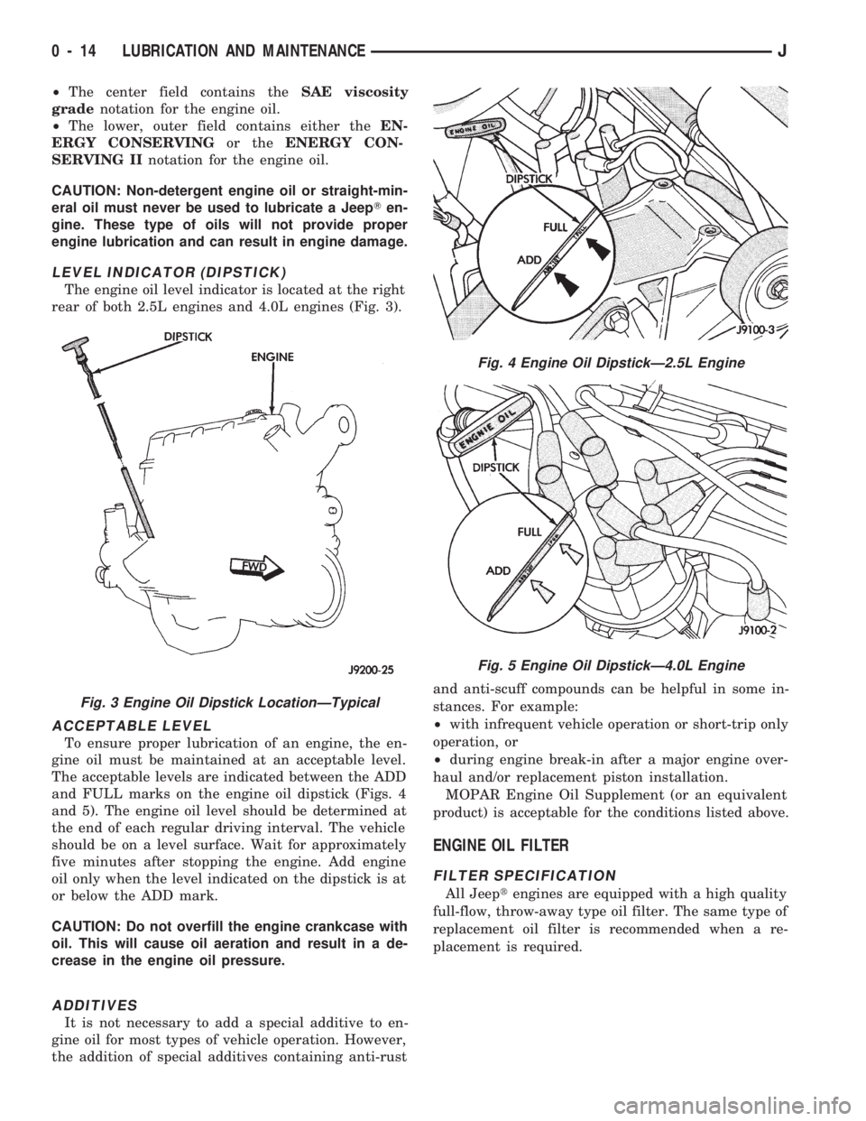
rear of both 2.5L engines and 4.0L engines (Fig. 3).
ACCEPTABLE LEVEL
To ensure proper lubrication of an engine, the en-
gine oil must be maintained at an acceptable level.
The acceptable levels are indicated between the ADD
and FULL marks on the engine oil dipstick (Figs. 4
and 5). The engine oil level should be determined at
the end of each regular driving interval. The vehicle
should be on a level surface. Wait for approximately
five minutes after stopping the engine. Add engine
oil only when the level indicated on the dipstick is at
or below the ADD mark.
CAUTION: Do not overfill the engine crankcase with
oil. This will cause oil aeration and result in a de-
crease in the engine oil pressure.
ADDITIVES
It is not necessary to add a special additive to en-
gine oil for most types of vehicle operation. However,
the addition of special additives containing anti-rustand anti-scuff compounds can be helpful in some in-
stances. For example:
²with infrequent vehicle operation or short-trip only
operation, or
²during engine break-in after a major engine over-
haul and/or replacement piston installation.
MOPAR Engine Oil Supplement (or an equivalent
product) is acceptable for the conditions listed above.
ENGINE OIL FILTER
FILTER SPECIFICATION
All Jeeptengines are equipped with a high quality
full-flow, throw-away type oil filter. The same type of
replacement oil filter is recommended when a re-
placement is required.
Fig. 3 Engine Oil Dipstick LocationÐTypical
Fig. 4 Engine Oil DipstickÐ2.5L Engine
Fig. 5 Engine Oil DipstickÐ4.0L Engine
0 - 14 LUBRICATION AND MAINTENANCEJ
Page 58 of 1784
Refer to Group 0, Lubrication and Maintenance for
additional information regarding temperature range,
viscosity and fluid level.
CAUTION: If the axle is submerged in water, the lu-
bricant must be replaced immediately to avoid the
possibility of premature axle failure.
DRIVE AXLE ASSEMBLY REPLACEMENTÐXJ
VEHICLES
REMOVAL
(1) Raise the vehicle and position support stands
under the frame rails slightly in behind the lower
suspension arm frame brackets.
(2) Remove the front wheels.
(3) Remove the brake components and ABS brake
sensor (if equipped). Refer to Group 5ÐBrakes.
(4) On 4WD vehicles, disconnect the axle vent
hose.
(5) On 4WD vehicles, mark the drive shaft yoke
and axle pinion yoke for alignment reference. Discon-
nect the drive shaft from the axle.
(6) Disconnect the stabilizer bar link at the axle
bracket.
(7) Disconnect the shock absorbers from axle
bracket.
(8) Disconnect the track bar from the axle bracket.
(9) Disconnect the tie rod and drag link from the
steering knuckle. Disconnect the steering dampener
from the axle bracket.
(10) Support the axle with a hydraulic jack under
the differential.
(11) Disconnect the upper and lower suspension
arms from the axle bracket.
(12) Lower the jack enough to remove the axle.
The coil springs will drop with the axle.
(13) Remove the coil springs from the axle bracket.
INSTALLATION
CAUTION: All suspension components that use rub-
ber bushings should be tightened with the vehicle
at the ride height. It is important to have the
springs supporting the weight of the vehicle when
the fasteners are torqued. If the springs are not at
their normal ride position, vehicle ride comfort
could be affected along with premature rubber
bushing wear. Rubber bushings must never be lu-
bricated.
(1) Install the springs and retainer clip. Tighten
the retainer bolts to 21 Nzm (16 ft. lbs.) torque.
(2) Support the axle on a hydraulic jack under the
differential. Position the axle under the vehicle.
(3) Raise the axle with a floor jack and align it
with the spring pads.(4) Position the upper and lower suspension arm at
the axle bracket. Install bolts and nuts finger
tighten.
(5) Connect the track bar to the axle bracket and
install the bolt.Do not tighten at this time.
It is important that the springs support the
weight of the vehicle when the track bar is con-
nected. If the springs are not at their usual po-
sition, the vehicle ride comfort could be affected.
(6) Install the shock absorber and tighten the bolt
to 19 Nzm (14 ft. lbs.) torque.
(7) Install the stabilizer bar link to the axle
bracket. Tighten the nut to 95 Nzm (70 ft. lbs.)
torque.
(8) Install the drag link and tie rod to the steering
knuckles and tighten the nuts to 47 Nzm (35 ft. lbs.)
torque. Install the steering dampener to the axle
bracket and tighten the nut to 75 Nzm (55 ft. lbs.)
torque.
(9) Install the brake components and ABS brake
sensor (if equipped). Refer to Group 5ÐBrakes.
(10) On 4WD vehicles, connect the vent hose to the
tube fitting.
(11) On 4WD vehicles, align the reference marks
and connect the drive shaft to the axle yoke. Tighten
the U-joint clamp bolts to 19 Nzm (14 ft. lbs.) torque.
(12) Check differential lubricant and add if neces-
sary.
(13) Install the wheel and tire assemblies.
(14) Remove the supports and lower the vehicle.
(15) Tighten the upper suspension arm nuts to 75
Nzm (55 ft. lbs.) torque. Tighten the lower suspension
arm nuts to 115 Nzm (85 ft. lbs.) torque.
(16) Tighten the track bar bolt at the axle bracket
to 100 Nzm (74 ft. lbs.) torque.
(17) Check the front wheel alignment.
DRIVE AXLE ASSEMBLY REPLACEMENTÐYJ
VEHICLES
REMOVAL
(1) Raise the vehicle and position support stands
under the frame rails slightly behind the spring
frame brackets.
(2) Remove the front wheels.
(3) Remove the brake components and ABS brake
sensor (if equipped). Refer to Group 5ÐBrakes.
(4) Disconnect the axle vent hose and axle shift
motor vacuum harness.
(5) Mark the drive shaft yoke and axle pinion yoke
for alignment reference. Disconnect the drive shaft
from the axle.
(6) Disconnect the stabilizer bar link at the axle
bracket.
(7) Disconnect the shock absorbers from axle
bracket.
(8) Disconnect the track bar from the axle bracket.
JFRONT SUSPENSION AND AXLE 2 - 21
Page 1680 of 1784
COMPRESSOR OVERHAUL
INDEX
page page
Compressor............................. 17
Compressor Isolation...................... 17
Description............................. 17Magnetic Clutch......................... 18
Purging Compressor of Air................. 17
DESCRIPTION
The A/C system uses a Sanden compressor. This
compressor is a 7 piston design. Designated the SD-
709, the compressor is mounted on the front right
side of the engine and is driven by a serpentine belt.
System lubrication is provided by 135cc615cc (4.6
cu. in.60.5 cu. in.) of 500 viscosity refrigerant oil.
The clutch used on the compressor consists of 3 ba-
sic components: the pulley, front plate and the field
coil. The pulley and field coil are attached to the
front head of the compressor with tapered snap rings.
The hub is keyed to the compressor shaft and is re-
tained on the shaft with a self-locking nut. Special
service tools are required to remove and install the
clutch plate on the compressor shaft.
COMPRESSOR ISOLATION
It is not necessary to discharge the system for com-
pressor removal. The compressor can be isolated from
the remainder of the system and eliminate the need
for recharging when performing compressor service.
(1) Connect pressure gauge and manifold.
(2) Close both gauge hand valves.
(3) Mid-position both service valves.
WARNING: USE EXTREME CAUTION WHEN THE
ENGINE IS OPERATING. DO NOT STAND IN A DI-
RECT LINE WITH THE FAN. DO NOT PUT YOUR
HANDS NEAR THE PULLEYS, BELTS OR FAN. DO
NOT WEAR LOOSE CLOTHING.
(4) Start the engine and operate the air condition-
ing system.
(5) Turn the suction service valve slowly clockwise
toward the front seated position.
(6) When pressure drops to zero, stop the engine
and compressor and quickly finish front-seating the
suction service valve.
(7) Front-seat the discharge service valve.
(8) Loosen the oil level check plug slowly to re-
lease any internal pressure in the compressor.
The compressor is now isolated from the remainder
of the system.
The service valves can be removed from the com-
pressor.
PURGING COMPRESSOR OF AIR
The compressor must be purged of air whenever it
has been isolated for an oil level check or other ser-
vice procedures without discharging the entire sys-
tem.
(1) Cap the service gauge ports on both of the ser-
vice valves.
(2) Back-seat the suction service valve to allow the
system refrigerant to enter the compressor.
(3) Place the discharge service valve in the mid-po-
sition or cracked-position.
(4) Loosen the discharge service valve gauge port
cap to permit the refrigerant to force any air out of
the compressor.
(5) Back-seat the discharge service valve and
tighten the gauge port cap.
(6) The compressor is now ready for service.
COMPRESSOR
REMOVAL
(1) Isolate the compressor.
(2) Disconnect negative cable from battery.
(3) Disconnect the clutch lead wire.
(4) Remove the discharge and inlet (suction) ser-
vice valves from the compressor. Plug or tape all the
openings.
(5) Remove the serpentine drive belt (refer to
Group 7, Cooling System for the proper procedure).
(6) Remove the bolts and lift the compressor from
the mounting bracket (Figs. 1 and 2).
INSTALLATION
If a replacement compressor is being installed;
check the oil level. Add or subtract oil as neces-
sary and install the magnetic clutch on the com-
pressor.
(1) If the mounting bracket was removed, install
the bracket to the block. Tighten the mounting bolts
to 27 NIm (20 ft. lbs.) torque.
(2) Install the compressor on the mounting
bracket. Tighten the bolts to 27 NIm (20 ft. lbs.)
torque.
(3) Install the serpentine drive belt (refer to Group
7, Cooling System for the proper procedure).
(4) Tighten the serpentine drive belt to the speci-
fied tension.
²New belt tensionÐ800-900 N (180-200 lb-f).
JHEATING AND AIR CONDITIONING 24 - 17