1994 JEEP CHEROKEE remote control
[x] Cancel search: remote controlPage 343 of 1784

IGNITION SWITCH
INDEX
page page
General Information....................... 30
Ignition Switch Installation/Adjustment......... 31Ignition Switch Removal................... 30
Ignition Switch Testing..................... 30
GENERAL INFORMATION
The ignition switch is mounted (under the instru-
ment panel) on the lower section of the steering col-
umn. The headlamp dimmer switch is mounted
beside the ignition switch (Fig. 1). Both of these
switches (ignition and dimmer) share the same
mounting screws.
The switch is connected to the ignition key lock as-
sembly by a remote actuator rod. This remote actua-
tor rod fits into an access hole on the bottom of the
ignition switch (Fig. 2).
IGNITION SWITCH REMOVAL
(1) Disconnect the negative battery cable at the
battery.
(2) XJ models: Remove the lower instrument panel
trim assembly. YJ models: Remove the windshield
wiper intermittent control module and its bracket (if
equipped).
(3) Place the ignition key lock in ACCESSORY po-
sition.
(4) Remove the two headlamp dimmer switch at-
taching nuts. Lift the switch from steering column
while disengaging actuator rod.Before removing dimmer switch, tape the two
remote control actuator rods (ignition switch
and dimmer) to the steering column. This will
prevent accidental disengagement from the up-
per part of the steering column.
(5) Remove the ignition switch-to-steering column
attaching screws.
(6) Disengage the ignition switch from the remote
actuator rod by lifting straight up. Remove switch
from steering column.
(7) Remove wiring from switch as follows:
Two electrical connectors are used to connect all
wiring to the ignition switch. One of the connectors
is installed (interlocked) over the top of the other
connector. Remove wiring from switch by disconnect-
ing the (black) harness connector first and then the
other connector. Remove the switch from the vehicle.
IGNITION SWITCH TESTING
To test the ignition switch circuity and continuity,
proceed as follows. Place the slide bar (on the igni-
tion switch) (Fig. 2) into the detent position to be
tested. An ohmmeter or continuity light may be used
to check switch continuity. Refer to the Ignition
Fig. 1 Ignition Switch/Headlamp Dimmer
SwitchÐTypical
Fig. 2 Ignition Switch/Remote Actuator
RodÐTypical
8D - 30 IGNITION SYSTEMSJ
Page 461 of 1784
ACTUATOR MOTOR STALL TEST
To test the actuator motor, connect an ammeter in
series with the motor and operate the door switch.
Replace the actuator motor if current draw exceeds 8
amps at room temperature or if the actuator does not
complete its travel in less than one second. Refer to
Solenoid and Latch Assembly Replacement procedures.
SWITCH REPLACEMENT
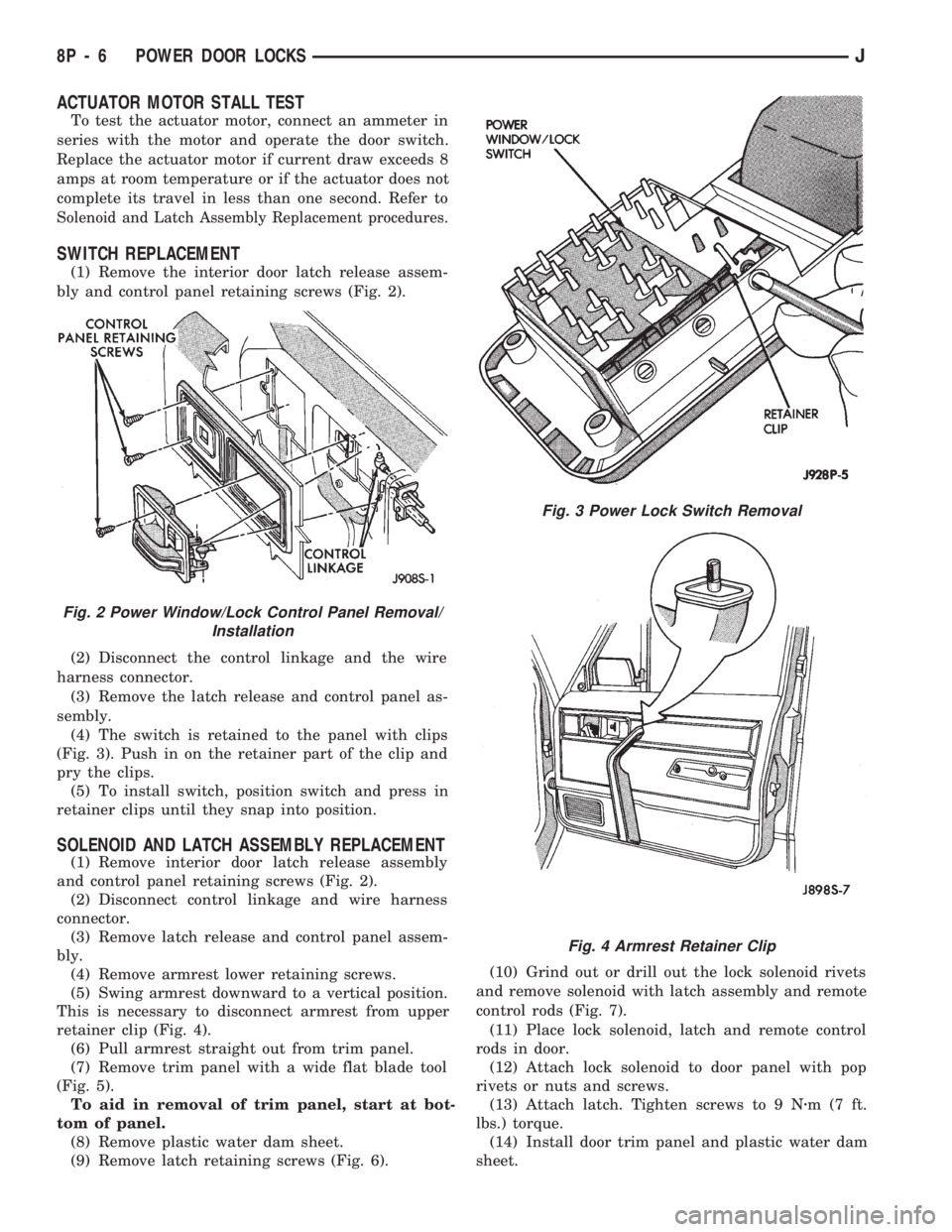
(1) Remove the interior door latch release assem-
bly and control panel retaining screws (Fig. 2).
(2) Disconnect the control linkage and the wire
harness connector.
(3) Remove the latch release and control panel as-
sembly.
(4) The switch is retained to the panel with clips
(Fig. 3). Push in on the retainer part of the clip and
pry the clips.
(5) To install switch, position switch and press in
retainer clips until they snap into position.
SOLENOID AND LATCH ASSEMBLY REPLACEMENT
(1) Remove interior door latch release assembly
and control panel retaining screws (Fig. 2).
(2) Disconnect control linkage and wire harness
connector.
(3) Remove latch release and control panel assem-
bly.
(4) Remove armrest lower retaining screws.
(5) Swing armrest downward to a vertical position.
This is necessary to disconnect armrest from upper
retainer clip (Fig. 4).
(6) Pull armrest straight out from trim panel.
(7) Remove trim panel with a wide flat blade tool
(Fig. 5).
To aid in removal of trim panel, start at bot-
tom of panel.
(8) Remove plastic water dam sheet.
(9) Remove latch retaining screws (Fig. 6).(10) Grind out or drill out the lock solenoid rivets
and remove solenoid with latch assembly and remote
control rods (Fig. 7).
(11) Place lock solenoid, latch and remote control
rods in door.
(12) Attach lock solenoid to door panel with pop
rivets or nuts and screws.
(13) Attach latch. Tighten screws to 9 Nzm(7ft.
lbs.) torque.
(14) Install door trim panel and plastic water dam
sheet.
Fig. 3 Power Lock Switch Removal
Fig. 2 Power Window/Lock Control Panel Removal/
Installation
Fig. 4 Armrest Retainer Clip
8P - 6 POWER DOOR LOCKSJ
Page 642 of 1784
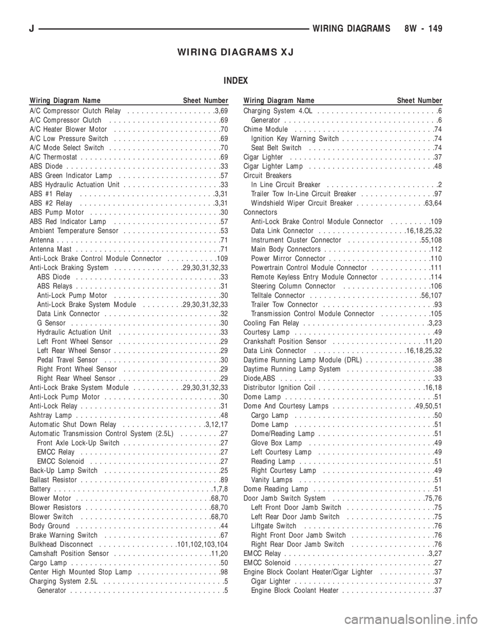
WIRING DIAGRAMS XJ
INDEX
Wiring Diagram Name Sheet Number
A/C Compressor Clutch Relay...................3,69
A/C Compressor Clutch........................69
A/C Heater Blower Motor.......................70
A/C Low Pressure Switch.......................69
A/C Mode Select Switch........................70
A/C Thermostat..............................69
ABS Diode.................................33
ABS Green Indicator Lamp......................57
ABS Hydraulic Actuation Unit.....................33
ABS #1 Relay.............................3,31
ABS #2 Relay.............................3,31
ABS Pump Motor............................30
ABS Red Indicator Lamp.......................57
Ambient Temperature Sensor.....................53
Antenna...................................71
Antenna Mast...............................71
Anti-Lock Brake Control Module Connector...........109
Anti-Lock Braking System...............29,30,31,32,33
ABS Diode...............................33
ABS Relays...............................31
Anti-Lock Pump Motor.......................30
Anti-Lock Brake System Module.........29,30,31,32,33
Data Link Connector.........................32
G Sensor................................30
Hydraulic Actuation Unit......................33
Left Front Wheel Sensor......................29
Left Rear Wheel Sensor.......................29
Pedal Travel Sensor.........................30
Right Front Wheel Sensor.....................29
Right Rear Wheel Sensor......................29
Anti-Lock Brake System Module...........29,30,31,32,33
Anti-Lock Pump Motor.........................30
Anti-Lock Relay..............................31
Ashtray Lamp...............................48
Automatic Shut Down Relay..................3,12,17
Automatic Transmission Control System (2.5L).........27
Front Axle Lock-Up Switch.....................27
EMCC Relay..............................27
EMCC Solenoid............................27
Back-Up Lamp Switch.........................25
Ballast Resistor..............................89
Battery..................................1,7,8
Blower Motor.............................68,70
Blower Resistors...........................68,70
Blower Switch............................68,70
Body Ground...............................44
Brake Warning Switch.........................67
Bulkhead Disconnect.................101,102,103,104
Camshaft Position Sensor.....................11,20
Cargo Lamp................................50
Center High Mounted Stop Lamp..................98
Charging System 2.5L..........................5
Generator.................................5Wiring Diagram Name Sheet Number
Charging System 4.OL..........................6
Generator.................................6
Chime Module..............................74
Ignition Key Warning Switch....................74
Seat Belt Switch...........................74
Cigar Lighter...............................37
Cigar Lighter Lamp...........................48
Circuit Breakers
In Line Circuit Breaker........................2
Trailer Tow In-Line Circuit Breaker................97
Windshield Wiper Circuit Breaker...............63,64
Connectors
Anti-Lock Brake Control Module Connector.........109
Data Link Connector...................16,18,25,32
Instrument Cluster Connector................55,108
Main Body Connectors.......................112
Power Mirror Connector......................110
Powertrain Control Module Connector.............111
Remote Keyless Entry Module Connector...........114
Steering Column Connector...................106
Telltale Connector........................56,107
Trailer Tow Connector........................93
Transmission Control Module Connector...........105
Cooling Fan Relay...........................3,23
Courtesy Lamp..............................49
Crankshaft Position Sensor....................11,20
Data Link Connector....................16,18,25,32
Daytime Running Lamp Module (DRL)...............38
Daytime Running Lamp System...................38
Diode,ABS.................................33
Distributor Ignition Coil.......................16,18
Dome Lamp................................51
Dome And Courtesy Lamps..................49,50,51
Cargo Lamp..............................50
Dome Lamp..............................51
Dome/Reading Lamp.........................51
Glove Box Lamp...........................49
Left Courtesy Lamp.........................49
Reading Lamp.............................51
Right Courtesy Lamp........................49
Vanity Lamps.............................51
Dome Reading Lamp..........................51
Door Jamb Switch System....................75,76
Left Front Door Jamb Switch...................75
Left Rear Door Jamb Switch...................75
Liftgate Switch............................76
Right Front Door Jamb Switch..................76
Right Rear Door Jamb Switch..................76
EMCC Relay...............................3,27
EMCC Solenoid..............................27
Engine Block Coolant Heater/Cigar Lighter............37
Cigar Lighter..............................37
Engine Block Coolant Heater....................37
JWIRING DIAGRAMS 8W - 149
Page 645 of 1784
Wiring Diagram Name Sheet Number
License Lamp...........................91,95
Low Washer Indicator Lamp..................57,58
Malfunction Indicator Lamp..................57,58
Maintenance Required Indicator Lamp...........57,58
Park Brake Indicator Lamp.....................58
Reading Lamp.............................51
Rear Wiper/Wash Switch Lamp..................47
Right Back-Up Lamp.......................92,96
Right Courtesy Lamp........................49
Right Fog Lamp............................40
Right Headlamp............................40
Right Park/Turn Signal Lamp...................40
Right Side Marker Lamp (Front).................40
Right Side Marker (Rear)....................92,96
Right Tail/Stop Lamp......................92,96
Right Turn Indicator Lamp.................59,60,61
Right Turn Lamp (Amber)...................92,96
Right Vanity Lamp..........................51
Seat Belt Warning Indicator Lamp..............57,58
Transfer Case Lamp.........................48
Transmission Range Switch Lamp................48
Underhood Lamp...........................34
Upshift Indicator Lamp.....................57,58
Vanity Lamps...........................51,53
L.C.D. Illumination Relay........................52
Left Front Door Connector And Door Lock Switch
Function Chart.............................87
Left Front Door Connector and Widow Lift Switch
Function Chart.............................87
Left Front Door Jamb Switch.....................75
Left Front Door Lock Motor......................86
Left Front Door Speaker........................71
Left Front Wheel Sensor........................29
Left Instrument Panel Speaker....................71
Left Liftgate Speaker..........................72
Left Power Seat Motor Assembly..................77
Left Power Seat Switch........................77
Left Rear Door Connector and Window Lift Switch
Function Chart.............................88
Left Rear Door Jamb Switch.....................75
Left Rear Door Window Switch...................82
Left Rear Wheel Sensor........................29
Left Turn Relay..............................97
Liftgate Switch..............................76
Liftgate Lock motor...........................86
Lo-Line Instrument Cluster Printed Circuit Board........60
Low Fuel Warning Module...................59,60,61
Low Washer Indicator Lamp...................57,58
Main Body Connectors........................112
Maintenance Required Indicator Lamp.............57,58
Malfunction Indicator Lamp....................57,58
Map Sensor..............................14,19
Modules
Anti-Lock Brake System Module.........29,30,31,32,33
Chime Module.............................74
Daytime Running Lamp Module.................38
Headlamp Delay Module......................43
Intermittent Wiper Module.....................64Wiring Diagram Name Sheet Number
Low Fuel Warning Module.................59,60,61
Powertrain Control Module. . . .11,12,13,14,15,16,17, 18,19,
20,21,22,23,35,36,45,55,69
Remote Keyless Entry Module...................28
Transmission Control Module.................25,26
Motors
ABS Pump Motor...........................30
A/C Heater Blower Motor......................70
Engine Starter Motor........................7,8
Front Wiper Motor........................63,64
Heater Blower Motor.........................68
Idle Air Control Motor......................15,22
Left Front Door Lock Motor....................86
Left Front Door Window Motor..................81
Left Power Mirror..........................73
Left Power Seat Motor Assembly................77
Left Rear Door Lock Motor....................86
Left Rear Door Window Motor..................82
Liftgate Lock Motor.........................86
Radiator Fan Motor.........................23
Rear Wiper Motor..........................65
Right Front Door Lock Motor...................86
Right Front Door Window Motor.................81
Right Power Mirror.........................73
Right Rear Door Lock Motor...................86
Right Rear Door Window Motor.................82
Oil Pressure Switch...........................24
Overhead Console System.....................53,54
Ambient Temperature Sensor...................53
Overhead Console..........................53
Vanity Lamps.............................53
Park Brake Switch............................67
Park Brake Indicator Lamp......................58
Parking Brake Switch..........................67
Park Lamp Relay.............................39
Park/Neutral Position Switch......................7
Pedal Travel Sensor...........................30
Power Distribution Center....................1,2,3,4
Power Distribution Center Application Chart............4
Power Distribution Center Identification...............3
Power Door Locks......................83,84,85,86
Left Door Lock Switch.......................85
Left Front Door Lock Motor....................86
Left Rear Door Lock Motor....................86
Liftgate Lock Motor.........................86
Power Door Lock Relay.......................83
Power Door Unlock Relay.....................83
Right Door Lock Switch......................85
Right Front Door Lock Motor...................86
Right Rear Door Lock Motor...................86
Power Door Lock Relay........................83
Power Door Unlock Relay.......................83
Power Mirror Connector.......................110
Power Mirror Connector and Switch Function Chart......88
Power Mirror Switch Assembly...................73
Power Mirror System..........................73
Left Power Mirror..........................73
Power Mirror Switch Assembly..................73
8W - 152 WIRING DIAGRAMSJ
Page 646 of 1784
Wiring Diagram Name Sheet Number
Right Power Mirror.........................73
Power Mirrors.............................73
Power Seat..............................77,78
Left Power Seat Motor Assembly................77
Left Power Seat Switch.......................78
Power Steering Pressure Switch...................15
Powertrain Control Module......11,12,13,14,15,16,17,18,19,
20,21,22,23,35,36,45,55,69
Powertrain Control Module (PCM) Connector..........111
Power Windows.......................79,80,81,82
Left Front Door Window Motor..................81
Left Rear Door Window Motor..................82
Left Rear Door Window Switch..................82
Power Window Switch.......................79
Right Front Door Window Switch................81
Right Front Door Window Motor.................81
Right Rear Door Window Motor.................82
Right Rear Door Window Switch.................82
Power Window Switch.........................79
Printed Circuit Boards.................57,58,59,60,61
Pumps
Front Washer...........................63,64
Rear Washer..............................65
Radiator Fan Motor...........................23
Radio....................................71
Antenna Mast.............................71
Left Front Door Speaker......................71
Left Instrument Panel Speaker..................71
Left Liftgate Speaker.........................72
Right Front Door Speaker.....................72
Right Instrument Panel Speaker.................72
Right Liftgate Speaker........................72
Reading Lamps..............................51
Rear Lighting...................91,92,93,94,95,96,97
Left Back-Up Lamp........................91,93
Left Side Marker Lamp (Rear)................91,93
Left Tail/Stop Lamp.......................91,93
Left Turn Lamp (Amber)....................91,93
Left Turn Relay............................97
License Lamp...........................91,95
Right Back-Up Lamp.......................92,96
Right Side Marker Lamp (Rear)...............92,96
Right Tail/Stop Lamp......................92,96
Right Turn Lamp (Amber)...................92,96
Right Turn Relay...........................97
Stop Lamp Relay...........................97
Trailer Tow Connector........................93
Trailer Tow In-Line Circuit Breaker................97
Rear Lighting With Trailer Tow............93,94,95,96,97
Rear Lighting Without Trailer Tow................91,92
Rear Washer Pump...........................65
Rear Wiper Motor............................65
Rear Wiper/Washer Motor.......................65
Rear Washer Pump...........................65
Rear Wiper Motor............................65
Rear Wiper/Washer Switch......................65
Rear Wiper/Washer Switch Lamp..................47
Reed Switch................................26Wiring Diagram Name Sheet Number
Relays
ABS #1 Relay............................3,31
ABS #2 Relay............................3,31
A/C Compressor Clutch Relay..................3,69
Automatic Shut Down Relay.................3,12,17
Cooling Fan Relay...........................3
EMCC Relay.............................3,27
Engine Starter Relay.......................3,7,8
Fan Control Relay...........................23
Fuel Pump Relay........................3,12,17
Heated Rear Window Relay....................66
High Beam Relay...........................40
Horn Relay...............................34
L.C.D. Illumination Relay......................52
Left Turn Relay............................97
Park Lamp Relay...........................39
Power Door Lock Relay.......................83
Power Door Unlock Relay.....................83
Right Turn Relay...........................97
Stop Lamp Relay...........................97
Relay Center Identification......................113
Remote Keyless Entry System....................28
Remote Keyless Entry Module...................28
Remote Keyless Entry Module Connector...........114
Resistor,Ballast..............................39
Resistor,Blower..............................68
Right Front Door Jamb Switch....................76
Right Front Door Speaker.......................72
Right Front Door Window Switch..................81
Right Front Wheel Sensor.......................29
Right Front Door Connector and Door Lock Switch
Function Chart.............................87
Right Front Door Lock Motor.....................86
Right Instrument Panel Speaker...................72
Right Liftgate Speaker.........................72
Right Front Door Window Connector and Window Lift
Switch Function Chart........................87
Right Rear Door Jamb Switch....................76
Right Rear Door Window Connector and Window Lift
Function Chart.............................88
Right Rear Wheel Sensor.......................29
Right Turn Relay.............................97
Seat Belt Switch.............................74
Seat Belt Warning Indicator Lamp................57,58
Sensors
Ambient Temperature Sensor...................53
Camshaft Position Sensor...................11,20
Crankshaft Position Sensor...................11,20
Engine Coolant Temperature Sensor.............14,19
G Sensor................................30
Heated Oxygen Sensor.....................13,21
Intake Air Temperature Sensor................14,19
Left Front Wheel Sensor......................29
Left Rear Wheel Sensor.......................29
MAP Sensor............................14,19
Pedal Travel Sensor.........................30
Right Front Wheel Sensor.....................29
Right Rear Wheel Sensor......................29
JWIRING DIAGRAMS 8W - 153
Page 1038 of 1784
STEERING
CONTENTS
page page
GENERAL INFORMATION.................. 1
MANUAL STEERING GEAR............... 35
NON-TILT STEERING COLUMN............ 50
POWER STEERING PUMP................. 9
POWER STEERING SYSTEM DIAGNOSIS..... 3
RECIRCULATING BALL POWER STEERING GEAR.19STEERING COLUMN GENERAL SERVICE.... 45
STEERING LINKAGEÐXJ................. 14
STEERING LINKAGEÐYJ................. 17
STEERING RHD........................ 69
TILT STEERING COLUMN................ 59
TORQUE SPECIFICATIONS................ 73
GENERAL INFORMATION
STEERING SYSTEM COMPONENTS
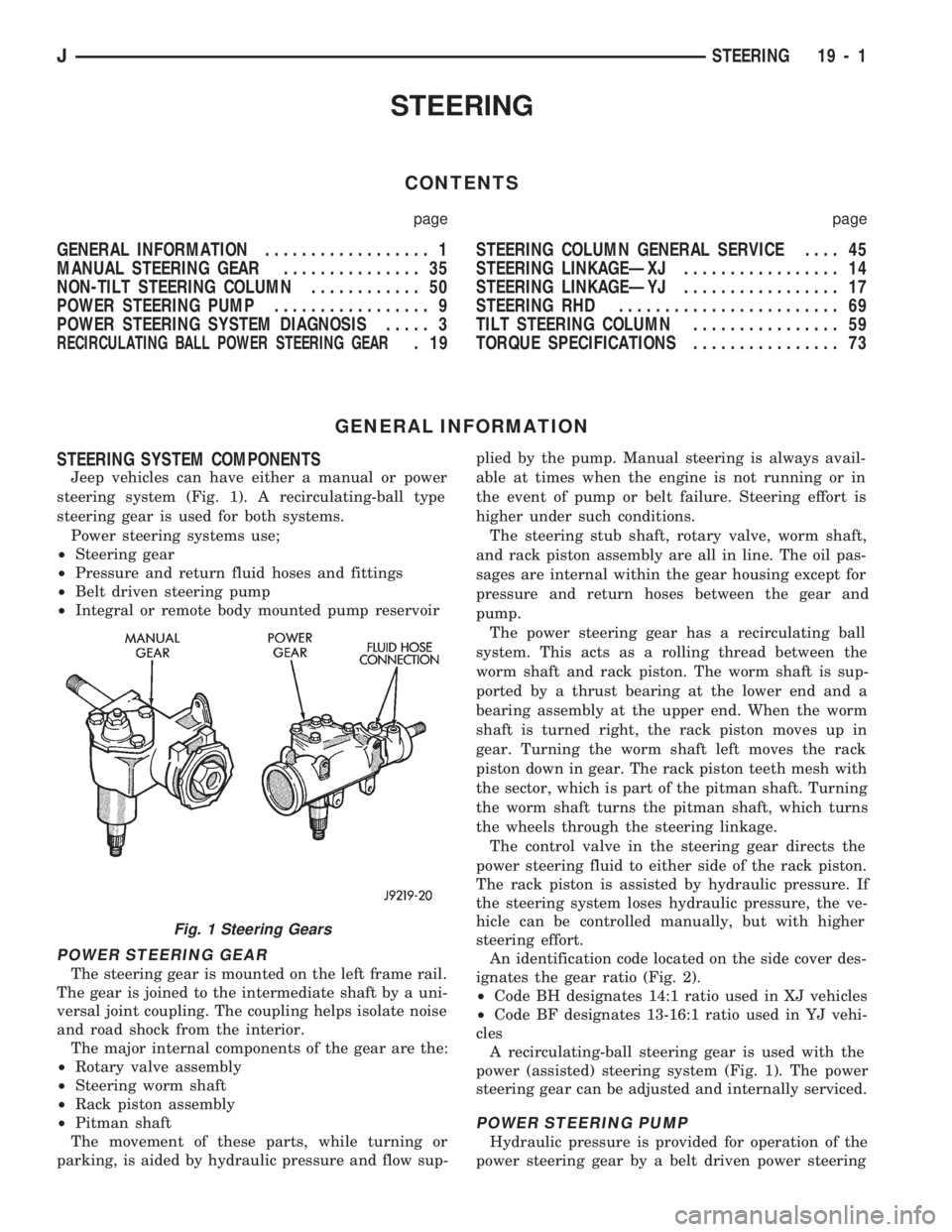
Jeep vehicles can have either a manual or power
steering system (Fig. 1). A recirculating-ball type
steering gear is used for both systems.
Power steering systems use;
²Steering gear
²Pressure and return fluid hoses and fittings
²Belt driven steering pump
²Integral or remote body mounted pump reservoir
POWER STEERING GEAR
The steering gear is mounted on the left frame rail.
The gear is joined to the intermediate shaft by a uni-
versal joint coupling. The coupling helps isolate noise
and road shock from the interior.
The major internal components of the gear are the:
²Rotary valve assembly
²Steering worm shaft
²Rack piston assembly
²Pitman shaft
The movement of these parts, while turning or
parking, is aided by hydraulic pressure and flow sup-plied by the pump. Manual steering is always avail-
able at times when the engine is not running or in
the event of pump or belt failure. Steering effort is
higher under such conditions.
The steering stub shaft, rotary valve, worm shaft,
and rack piston assembly are all in line. The oil pas-
sages are internal within the gear housing except for
pressure and return hoses between the gear and
pump.
The power steering gear has a recirculating ball
system. This acts as a rolling thread between the
worm shaft and rack piston. The worm shaft is sup-
ported by a thrust bearing at the lower end and a
bearing assembly at the upper end. When the worm
shaft is turned right, the rack piston moves up in
gear. Turning the worm shaft left moves the rack
piston down in gear. The rack piston teeth mesh with
the sector, which is part of the pitman shaft. Turning
the worm shaft turns the pitman shaft, which turns
the wheels through the steering linkage.
The control valve in the steering gear directs the
power steering fluid to either side of the rack piston.
The rack piston is assisted by hydraulic pressure. If
the steering system loses hydraulic pressure, the ve-
hicle can be controlled manually, but with higher
steering effort.
An identification code located on the side cover des-
ignates the gear ratio (Fig. 2).
²Code BH designates 14:1 ratio used in XJ vehicles
²Code BF designates 13-16:1 ratio used in YJ vehi-
cles
A recirculating-ball steering gear is used with the
power (assisted) steering system (Fig. 1). The power
steering gear can be adjusted and internally serviced.
POWER STEERING PUMP
Hydraulic pressure is provided for operation of the
power steering gear by a belt driven power steering
Fig. 1 Steering Gears
JSTEERING 19 - 1
Page 1102 of 1784
(13) Install all support attaching screws finger-
tight. Next, tighten the screws alternately and evenly
to7Nzm (60 in. lbs.) torque.
(14) Install the remote rod in the support. Route
the rod through the upper end of the shroud and in-
sert it into the rod slot located in the support.
(15) Install the dimmer switch and ignition switch.
(16) Install the steering shaft in the steering col-
umn.
(17) Install replacement races and bearings in the
key/lock cylinder, if removed.Ensure that the bear-
ings are lubricated with chassis lubricant be-
fore installation.
(18) Install the lock shoes, the lock shoe springs
and the lock shoe pin the key/lock cylinder housing.
Use a 4.5-mm (0.18-in) diameter rod to align the
shoes and the pin during installation.
(19) Install the tilt-release lever, the lever spring
and the lever pin in the key/lock cylinder housing.
Insert a wedge between the housing and the lever to
relieve the spring tension. This will allow easier re-
lease lever pin installation.
(20) Install the lock bolt in the key/lock cylinder
housing and engage it in the lock sector cam surface.
(21) Install the lock rack, the rack preload spring
and a replacement shim in the key/lock cylinder
housing. Align and mate the square block tooth on
the lock rack and the lock sector.
(22) Install the lock spring and the spring retain-
ing screw. Tighten the screw to 4 Nzm (35 in. lbs.)
torque.
(23) Align and install the assembled key/lock cylin-
der housing on the support. Retain the lock shoes in
the disengaged position for easier housing installa-
tion.(24) Align the pivot pin holes in the housing with
those in the support. Insert the pivot pins.Press the
housing firmly downward when inserting the
pivot pins. This prevents damaging the holes in
the support.When the pivot pins are within both
the housing and the support holes, seat them fully
with a punch and a hammer.
(25) Insert tilt-release lever in key/lock cylinder
housing and place housing in the full-upward tilt po-
sition.
(26) Lubricate the tilt spring guide and the tilt
spring liberally with chassis lubricant and position
the spring on the guide.
(27) Insert the tilt spring guide and the spring into
the key/lock cylinder housing. Install the guide re-
tainer over the spring. Engage the retainer lock tabs
with the housing lugs by pressing the retainer down-
ward and turning clockwise with a screwdriver.
(28) Place the cover on the key/lock cylinder hous-
ing. Align and install the cover retaining screws.
Tighten the screws to 7 Nzm (60 in. lbs.) torque.
(29) Install the gear selector indicator lamp mount-
ing bracket screw.
(30) Install the gear selector indicator cover and
retaining screws.
(31) Route the dimmer switch wire harness and
gear selector indicator down through the steering col-
umn.
(32) To install ignition switch lock, turn the key to
the LOCK position and remove the key. This will
cause the buzzer operating lever to retract in the
key/lock cylinder. Now insert the key/lock cylinder
into the housing far enough to contact the drive
shaft. Force it inward and move the ignition switch
actuator rod up and down to align the components.
When the components align, the key/lock cylinder
will move inward and the spring-loaded retainer will
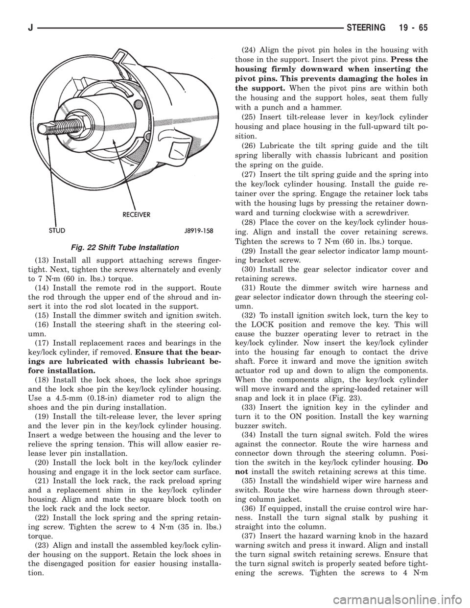
snap and lock it in place (Fig. 23).
(33) Insert the ignition key in the cylinder and
turn it to the ON position. Install the key warning
buzzer switch.
(34) Install the turn signal switch. Fold the wires
against the connector. Route the wire harness and
connector down through the steering column. Posi-
tion the switch in the key/lock cylinder housing.Do
notinstall the switch retaining screws at this time.
(35) Install the windshield wiper wire harness and
switch. Route the wire harness down through steer-
ing column jacket.
(36) If equipped, install the cruise control wire har-
ness. Install the turn signal stalk by pushing it
straight into the column.
(37) Insert the hazard warning knob in the hazard
warning switch and press it inward. Align and install
the turn signal switch retaining screws. Ensure that
the turn signal switch is properly seated before tight-
ening the screws. Tighten the screws to 4 Nzm
Fig. 22 Shift Tube Installation
JSTEERING 19 - 65
Page 1105 of 1784
(25) Install the windshield wiper wire harness and
switch. Route the wire harness down through steer-
ing column jacket.
(26) If equipped, install the cruise control wire har-
ness. Install the turn signal stalk by pushing it
straight into the column.
(27) Insert the hazard warning knob in the hazard
warning switch and press it inward. Align and install
the turn signal switch retaining screws. Ensure that
the turn signal switch is properly seated before tight-
ening the screws. Tighten the screws to 4 Nzm (33 in.
lbs.) torque. Thread the hazard warning switch knob
into the switch and pull the knob outward.
(28) Install and seat the upper bearing race in the
key/lock cylinder housing.
(29) Install the upper bearing preload spring, the
canceling cam and the lockplate.
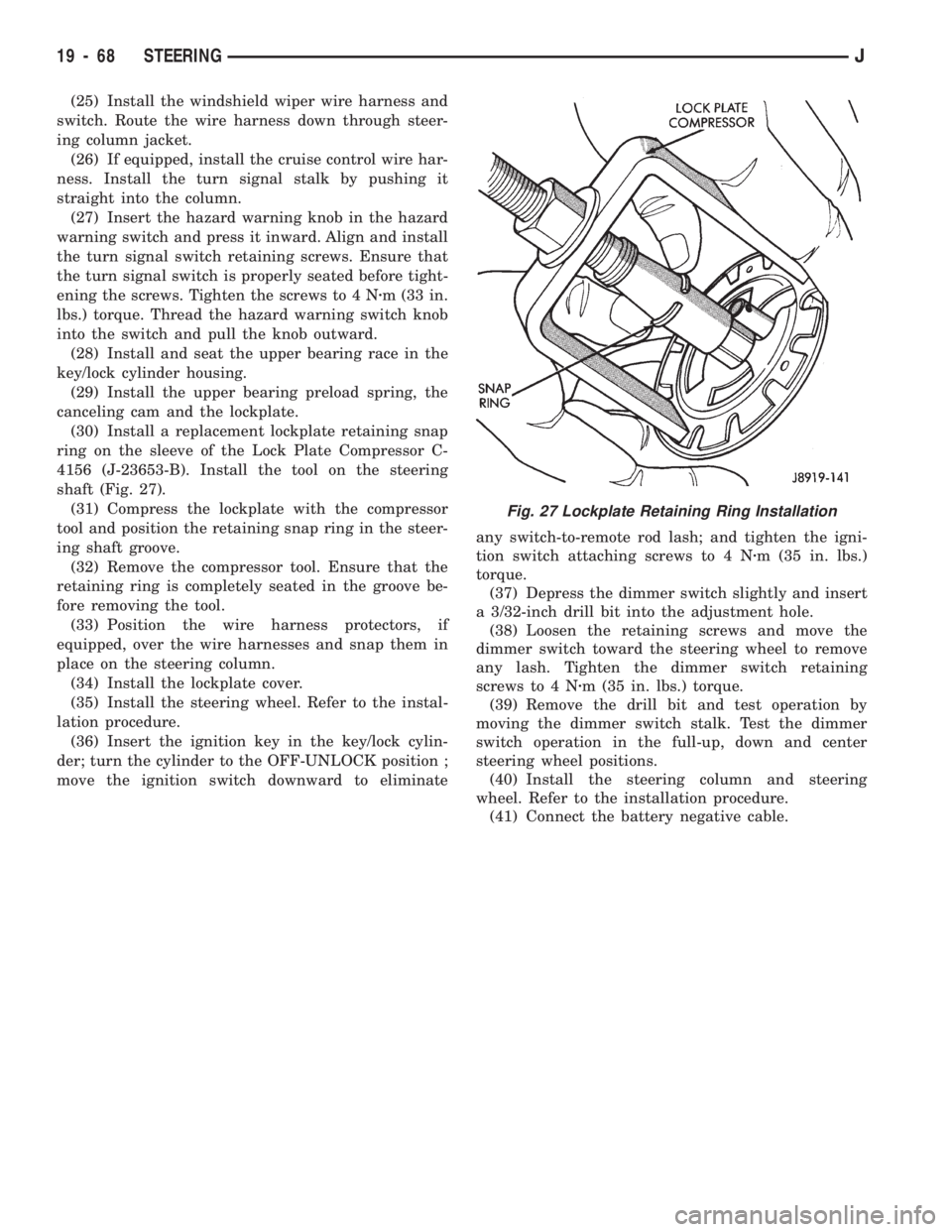
(30) Install a replacement lockplate retaining snap
ring on the sleeve of the Lock Plate Compressor C-
4156 (J-23653-B). Install the tool on the steering
shaft (Fig. 27).
(31) Compress the lockplate with the compressor
tool and position the retaining snap ring in the steer-
ing shaft groove.
(32) Remove the compressor tool. Ensure that the
retaining ring is completely seated in the groove be-
fore removing the tool.
(33) Position the wire harness protectors, if
equipped, over the wire harnesses and snap them in
place on the steering column.
(34) Install the lockplate cover.
(35) Install the steering wheel. Refer to the instal-
lation procedure.
(36) Insert the ignition key in the key/lock cylin-
der; turn the cylinder to the OFF-UNLOCK position ;
move the ignition switch downward to eliminateany switch-to-remote rod lash; and tighten the igni-
tion switch attaching screws to 4 Nzm (35 in. lbs.)
torque.
(37) Depress the dimmer switch slightly and insert
a 3/32-inch drill bit into the adjustment hole.
(38) Loosen the retaining screws and move the
dimmer switch toward the steering wheel to remove
any lash. Tighten the dimmer switch retaining
screws to 4 Nzm (35 in. lbs.) torque.
(39) Remove the drill bit and test operation by
moving the dimmer switch stalk. Test the dimmer
switch operation in the full-up, down and center
steering wheel positions.
(40) Install the steering column and steering
wheel. Refer to the installation procedure.
(41) Connect the battery negative cable.
Fig. 27 Lockplate Retaining Ring Installation
19 - 68 STEERINGJ