Page 1487 of 1784

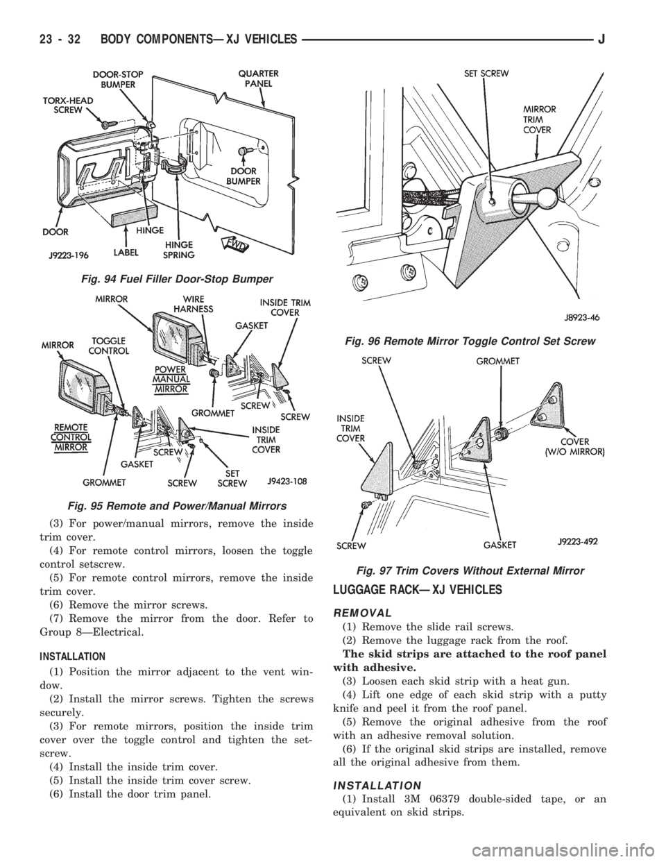
(3) For power/manual mirrors, remove the inside
trim cover.
(4) For remote control mirrors, loosen the toggle
control setscrew.
(5) For remote control mirrors, remove the inside
trim cover.
(6) Remove the mirror screws.
(7) Remove the mirror from the door. Refer to
Group 8ÐElectrical.
INSTALLATION
(1) Position the mirror adjacent to the vent win-
dow.
(2) Install the mirror screws. Tighten the screws
securely.
(3) For remote mirrors, position the inside trim
cover over the toggle control and tighten the set-
screw.
(4) Install the inside trim cover.
(5) Install the inside trim cover screw.
(6) Install the door trim panel.
LUGGAGE RACKÐXJ VEHICLES
REMOVAL
(1) Remove the slide rail screws.
(2) Remove the luggage rack from the roof.
The skid strips are attached to the roof panel
with adhesive.
(3) Loosen each skid strip with a heat gun.
(4) Lift one edge of each skid strip with a putty
knife and peel it from the roof panel.
(5) Remove the original adhesive from the roof
with an adhesive removal solution.
(6) If the original skid strips are installed, remove
all the original adhesive from them.
INSTALLATION
(1) Install 3M 06379 double-sided tape, or an
equivalent on skid strips.
Fig. 94 Fuel Filler Door-Stop Bumper
Fig. 95 Remote and Power/Manual Mirrors
Fig. 96 Remote Mirror Toggle Control Set Screw
Fig. 97 Trim Covers Without External Mirror
23 - 32 BODY COMPONENTSÐXJ VEHICLESJ
Page 1580 of 1784

PARKING BRAKE HANDLE COVERÐXJ
VEHICLES
REMOVAL
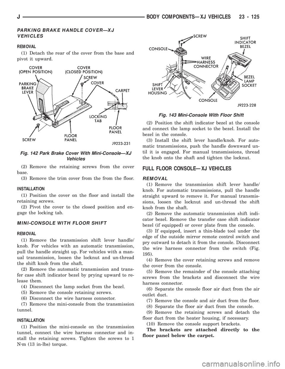
(1) Detach the rear of the cover from the base and
pivot it upward.
(2) Remove the retaining screws from the cover
base.
(3) Remove the trim cover from the from the floor.
INSTALLATION
(1) Position the cover on the floor and install the
retaining screws.
(2) Pivot the cover to the closed position and en-
gage the locking tab.
MINI-CONSOLE WITH FLOOR SHIFT
REMOVAL
(1) Remove the transmission shift lever handle/
knob. For vehicles with an automatic transmission,
pull the handle straight up. For vehicles with a man-
ual transmission, loosen the locknut and un-thread
the shift knob from the shaft.
(2) Remove the automatic transmission and trans-
fer case shift indicator bezel by prying upward to re-
lease them.
(4) Disconnect the lamp socket from the bezel.
(5) Remove the console retaining screws.
(6) Disconnect the wire harness connector.
(7) Remove the mini-console from the transmission
tunnel.
INSTALLATION
(1) Position the mini-console on the transmission
tunnel, connect the wire harness connector and in-
stall the retaining screws. Tighten the screws to 1
Nzm (13 in-lbs) torque.(2) Position the shift indicator bezel at the console
and connect the lamp socket to the bezel. Install the
bezel in the console.
(3) Install the shift lever handle/knob. For auto-
matic transmissions, push the handle downward un-
til it is engaged. For manual transmissions, thread
the knob onto the shaft and tighten the locknut.
FULL FLOOR CONSOLEÐXJ VEHICLES
REMOVAL
(1) Remove the transmission shift lever handle/
knob. For automatic transmissions, pull the handle
straight upward to remove it. For manual transmis-
sions, loosen the locknut and un-thread the shift
knob from the shaft.
(2) Remove the automatic transmission shift indi-
cator bezel. Remove the transfer case shift indicator
bezel (if equipped) or cover plate from the console.
(3) If equipped, insert a thin-blade tool under the
edge of the outside mirror remote control switch and
pry outward to detach it from the console. Disconnect
the wire harness connector from the switch (Fig.
195).
(4) Remove the cover retaining screws and remove
the cover from the console.
(5) Remove the remainder of the console attaching
screws from the brackets and disconnect the wire
harness connector.
(6) Separate the console floor air duct from the air
outlet duct.
(7) Remove the console and air duct from the floor.
(8) Separate the floor air duct from the console.
(9) Remove the retaining screws and detach the
floor duct from the heater housing, if necessary.
(10) Remove the console support brackets.
The brackets are attached directly to the
floor panel below the carpet.
Fig. 142 Park Brake Cover With Mini-ConsoleÐXJ
Vehicles
Fig. 143 Mini-Console With Floor Shift
JBODY COMPONENTSÐXJ VEHICLES 23 - 125
Page 1581 of 1784
INSTALLATION
(1) Install the console support brackets, if re-
moved. Tighten the screws to 1 Nzm (11 In-lbs)
torque.
The brackets are attached directly to the
floor panel below the carpet.
(2) Attach the floor duct to the heater housing, if
removed. Tighten the screws to 1 Nzm (11 In-lbs)
torque.
(2) Attach the air duct to the console.(3) Position the console on the floor, attach the air
duct to the air outlet duct, connect the wire harness
connector and install the console retaining screws in
the brackets. Tighten the screws to 1 Nzm (11 In-lbs)
torque.
(4) Install the console cover and shift indicator be-
zels (or cover plate). Tighten the screws to 1 Nzm(11
In-lbs) torque.
(5) If equipped:
Fig. 146 Outside Mirror Remote Control SwitchÐXJ
Vehicles
Fig. 144 Full ConsoleÐXJ Vehicles
Fig. 145 Transfer Case Shift Indicator Bezel/Cover
Plate
23 - 126 BODY COMPONENTSÐXJ VEHICLESJ
Page 1582 of 1784
²connect the wire harness connector to the outside
mirror remote control switch,
²insert the switch into the console hole, and
²push inward to engage the retaining clips.
(6) Install the shift lever handle/knob.
JACK STORAGEÐXJ VEHICLES
SERVICE INFORMATION
The XJ lift jack and related tools are stored under
the rear seat behind the front passenger's seat. The
jack and tools are attached to the floor panel and
seat cushion crossmember with a retainer and hold-
down bolt.
When necessary, the jack retainer bracket can be
removed from the crossmember by drilling-out the
rivet heads and then removing the rivet bodies with
a punch. Install the retainer bracket with either riv-
ets or bolts and nuts.
Fig. 147 Full Console Removal/Installation
Fig. 148 Air Outlet and Console Floor Air Ducts
Fig. 149 Floor Duct Removal/Installation
Fig. 150 Floor Console Support Brackets
Fig. 151 Jack and Related ToolsÐXJ Vehicles
JBODY COMPONENTSÐXJ VEHICLES 23 - 127