1994 JEEP CHEROKEE trailer
[x] Cancel search: trailerPage 2 of 1784
LUBRICATION AND MAINTENANCE
CONTENTS
page page
CHASSIS AND BODY COMPONENTS....... 30
DRIVETRAIN........................... 22
ENGINE MAINTENANCE.................. 13GENERAL INFORMATION.................. 1
JUMP STARTING, HOISTING AND TOWING . . 7
MAINTENANCE SCHEDULES............... 5
GENERAL INFORMATION
INDEX
page page
Classification of Lubricants.................. 2
Components Requiring No Lubrication.......... 3
Fluid Capacities.......................... 4
Fuel Requirements........................ 2Introduction.............................. 1
Recommended Lubricant and Replacement Parts . 3
Routine Service........................... 2
INTRODUCTION
Jeeptlubrication and maintenance is divided into
required and recommended service tasks.
The recommendations and procedures listed in this
group are intended for JeeptDealer Service Personnel.
Because conditions vary, it is necessary to schedule
service tasks according to a time interval as well as a
distance interval.
It is the owner's responsibility to have vehicle ser-
viced. Owner is to pay for labor and necessary parts
that are not covered by the warranty.
Additional lubrication and maintenance informa-
tion is listed in the Owner's Manual, which is in-
cluded with the vehicle.
SEVERE DRIVING CONDITIONS
When a vehicle is subjected to a severe driving con-
dition, time between recommended maintenance
should be decreased.
Refer to Engine Maintenance for the engine oil and
filter maintenance interval when involved with a se-
vere driving condition.
A severe driving condition is defined as either:
²frequent short trip driving less than 24 km (15
miles);
²frequent driving in a dusty environment;
²trailer towing;
²extensive engine idling;
²sustained high-speed operation;
²desert operation;
²frequent starting and stopping;²cold-climate operation;
²off-road driving; or
²commercial service.
To service a Jeeptvehicle for a severe driving con-
dition, change all the lubricating fluids and lubricate:
²the body components,
²all the driveline coupling joints, and
²the steering linkage
more often than for a normal driving condition to
prevent excessive wear of the components.
DUSTY AREAS
Driving in an area with dust-filled air increases the
risk of particles entering the engine and crankcase.
With this type of severe driving condition, attention
should be given to the engine and crankcase compo-
nents.
OFF-ROAD (4WD) OPERATION
After completion of off-road (4WD) operation, the
underside of the vehicle should be thoroughly in-
spected. Examine threaded fasteners for looseness.
HARSH SURFACE ENVIRONMENTS
After vehicle operation in a harsh surface environ-
ment, the following components should be inspected
and cleaned as soon as possible:
²brake drums,
²brake linings,
²front wheel bearings (2WD vehicles only), and
²axle coupling joints.
This will prevent wear and/or unpredictable brake
action.
JLUBRICATION AND MAINTENANCE 0 - 1
Page 6 of 1784

MAINTENANCE SCHEDULES
INTRODUCTION
Chrysler Corporation has compiled recommended
lubrication and maintenance schedules and proce-
dures to help reduce premature wear or failure over
a broad range of operating conditions.
SEVERE SERVICE MAINTENANCE
If the vehicle is involved with a severe driving con-
dition, after each 4 800-km (3,000-miles)/3-month in-
terval. A severe driving condition includes:
²frequent short trip driving less than 24 km (15
miles);
²frequent driving in a dusty environment;
²trailer towing;
²extensive engine idling;
²sustained high-speed operation;
²desert operation;
²frequent starting and stopping;
²cold-climate operation;
²off-road driving; or
²commercial service.
MAINTENANCE SCHEDULES
AT EACH STOP FOR FUEL
²Check engine oil level, add as required.
²
Check windshield washer solvent and add if required.
ONCE A MONTH
²Check tire pressure and look for unusual wear or
damage.
²Inspect battery and clean and tighten terminals as
required.
²Check electrolyte level and add water as needed.
²Check fluid levels of coolant reservoir, power steer-
ing and transmission and add as needed.
²Check all lights and all other electrical items for
correct operation.
²Check rubber seals on each side of the radiator for
proper fit.
7,500 MILES (12 000 KM) OR AT 6 MONTHS
²Check engine coolant level, hoses and clamps.
²Change engine oil.
²Replace engine oil filter.
²Check exhaust system.
²Lubricate steering linkage (4x4 models).
²Lubricate propeller shaft universal joints.
²Rotate Tires.
15,000 MILES (24 000 KM) OR AT 12 MONTHS
²Check engine coolant level, hoses and clamps.
²Change engine oil.
²Replace engine oil filter.
²Check exhaust system.
²Lubricate steering linkage (4x4 models).
²Lubricate propeller shaft universal joints.²Check fluid level in battery.
²Rotate Tires.
22,500 MILES (36 000 KM) OR AT 18 MONTHS
²Check engine coolant level, hoses and clamps.
²Change engine oil.
²Replace engine oil filter.
²Check exhaust system.
²Lubricate steering linkage (4x4 models).
²Lubricate propeller shaft universal joints.
²Rotate Tires.
30,000 MILES (48 000 KM) OR AT 24 MONTHS
²Replace air cleaner filter.
²Replace spark plugs.
²Adjust drive belt.
²Check engine coolant level, hoses and clamps.
²Change engine oil.
²Replace engine oil filter.
²Check exhaust system.
²Lubricate steering linkage (4x4 models).
²Lubricate propeller shaft universal joints.
²Check fluid level in battery.
²Drain and refill automatic transmission.
²Drain and refill transfer case.
²Rotate Tires.
37,500 MILES (60 000 KM) OR AT 30 MONTHS
²Check engine coolant level, hoses and clamps.
²Change engine oil.
²Replace engine oil filter.
²Check exhaust system.
²Lubricate steering linkage (4x4 models).
²Lubricate propeller shaft universal joints.
²Drain and refill manual transmission.
²Rotate Tires.
45,000 MILES (72 500 KM) OR AT 36 MONTHS
²Check engine coolant level, hoses and clamps.
²Change engine oil.
²Replace engine oil filter.
²Check exhaust system.
²Lubricate steering linkage (4x4 models).
²Lubricate propeller shaft universal joints.
²Check fluid level in battery.
²Rotate Tires.
52,500 MILES (84 500 KM) OR AT 42 MONTHS
²Flush and replace engine coolant.
²Check engine coolant system hoses and clamps.
²Change engine oil.
²Replace engine oil filter.
²Check exhaust system.
²Lubricate steering linkage (4x4 models).
²Lubricate propeller shaft universal joints.
²Rotate Tires.
JLUBRICATION AND MAINTENANCE 0 - 5
Page 16 of 1784
ENGINE OIL CHANGE AND FILTER REPLACEMENT
WARNING: CARE SHOULD BE TAKEN WHEN
CHANGING OIL. PROTECTIVE CLOTHING AND
GLOVES SHOULD BE WORN. EXPOSED SKIN
SHOULD BE WASHED WITH SOAP AND WATER TO
REMOVE ANY ENGINE OIL. DO NOT USE GASO-
LINE, THINNER, OR SOLVENTS TO REMOVE EN-
GINE OIL FROM SKIN.
REQUIRED MAINTENANCE
With normal driving conditions, engine oil and fil-
ter must be changed after each 12 000-km (7,500-
miles)/12-month interval. If the vehicle is involved
with a severe driving condition, after each 4 800-km
(3,000-miles)/3-month interval. A severe driving con-
dition includes:
²frequent short trip driving less than 24 km (15
miles);
²frequent driving in a dusty environment;
²trailer towing;
²extensive engine idling;
²sustained high-speed operation;
²desert operation;
²frequent starting and stopping;
²cold-climate operation;
²off-road driving; or
²commercial service.
OIL CHANGE AND FILTER REPLACEMENT
(1) Drain the engine oil from the crankcase. Wait
until after the engine has attained the normal oper-
ating temperature to ensure complete drainage of oil.
(2) Install the drain-hole plug with a replacement
gasket.
The oil filter should be replaced during every
engine oil change.
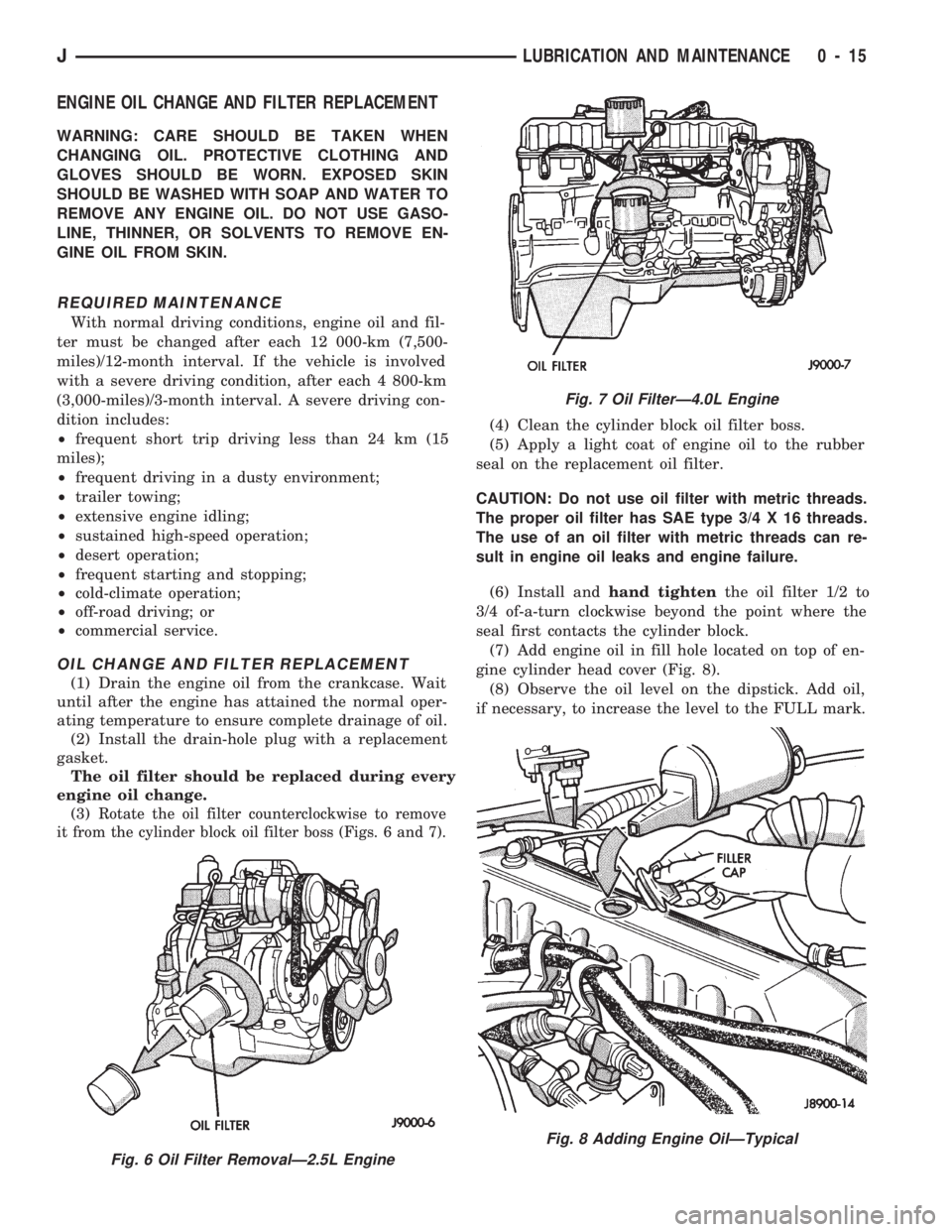
(3)
Rotate the oil filter counterclockwise to remove
it from the cylinder block oil filter boss (Figs. 6 and 7).
(4) Clean the cylinder block oil filter boss.
(5) Apply a light coat of engine oil to the rubber
seal on the replacement oil filter.
CAUTION: Do not use oil filter with metric threads.
The proper oil filter has SAE type 3/4 X 16 threads.
The use of an oil filter with metric threads can re-
sult in engine oil leaks and engine failure.
(6) Install andhand tightenthe oil filter 1/2 to
3/4 of-a-turn clockwise beyond the point where the
seal first contacts the cylinder block.
(7) Add engine oil in fill hole located on top of en-
gine cylinder head cover (Fig. 8).
(8) Observe the oil level on the dipstick. Add oil,
if necessary, to increase the level to the FULL mark.
Fig. 6 Oil Filter RemovalÐ2.5L Engine
Fig. 7 Oil FilterÐ4.0L Engine
Fig. 8 Adding Engine OilÐTypical
JLUBRICATION AND MAINTENANCE 0 - 15
Page 27 of 1784
If the transfer case ATF is warm, it is accept-
able for the fluid to drip out of the fill hole. If
the fluid gushes out of the fill hole, the level is
too high.
(3) If the level is low, raise it to the bottom edge of
the fill hole with MOPAR ATF PLUS type 7176 or
an equivalent MerconŸ/Dexron IIŸ ATF.
(4) Install the fill-hole plug. Tighten the plug with
47 NIm (35 ft. lbs.) torque.
(5) Remove the support and lower the vehicle.
FLUID CHANGE
When it becomes necessary to change the ATF in a
Jeepttransfer case, use the following procedure.
(1) Raise and support the vehicle.
(2) Remove the fill-hole plug from the transfer
case.
(3) Place an appropriate container under the trans-
fer case drain-hole plug.
(4) Remove the drain-hole plug and drain the ATF
from the transfer case into the container.
Care should be exercised when disposing used
ATF after it has been drained from a transfer
case.
CAUTION: Do not over-tighten the drain and fill-hole
plugs. Over-tightening can strip the hole threads
and/or crack the aluminum housing.
(5) Install the drain-hole plug in the transfer case.
Tighten the plug with 47 NIm (35 ft. lbs.) torque.
(6) Fill the transfer case to the bottom edge of the
fill hole with MOPAR ATF PLUS type 7176 (or an
equivalent MerconŸ/Dexron IIŸ ATF).
(7) Install the fill-hole plug in the transfer case.
Tighten the plug with 47 NIm (35 ft. lbs.) torque.
(8) Remove the support and lower the vehicle.
FRONT AND REAR AXLES
RECOMMENDED MAINTENANCE
The lubricant level in axle differential housings
should be determined at the same time as the engine
oil is changed and the oil filter is replaced. Add lu-
bricant as necessary.
In addition, with normal driving conditions, the
axle lubricant should be changed after each 48
000-km (30,000-miles). With severe driving condi-
tions, after each 29 000-km (12,000-miles).
LUBRICANT SPECIFICATIONS
For normal vehicle operation, use SAE 75W-90,
API Quality Grade GL-5 gear lubricant in all Jeept
front (4WD only) and rear axles. Vehicles equipped
with a Trac-Loc rear axle also require a friction mod-
ifier additive with the gear lubricant.
When involved in trailer towing applications
use SAE 80W-140, API Quality Grade GL-5 gearlubricant in the rear axle. XJ Vehicles equipped
with a class III trailer hitch require SAE
75W-140 synthetic gear lubricant in the rear
axle.
LUBRICANT LEVEL
Determine the axle differential housing lubricant
level according to the following procedure.
(1) Raise and support the vehicle.
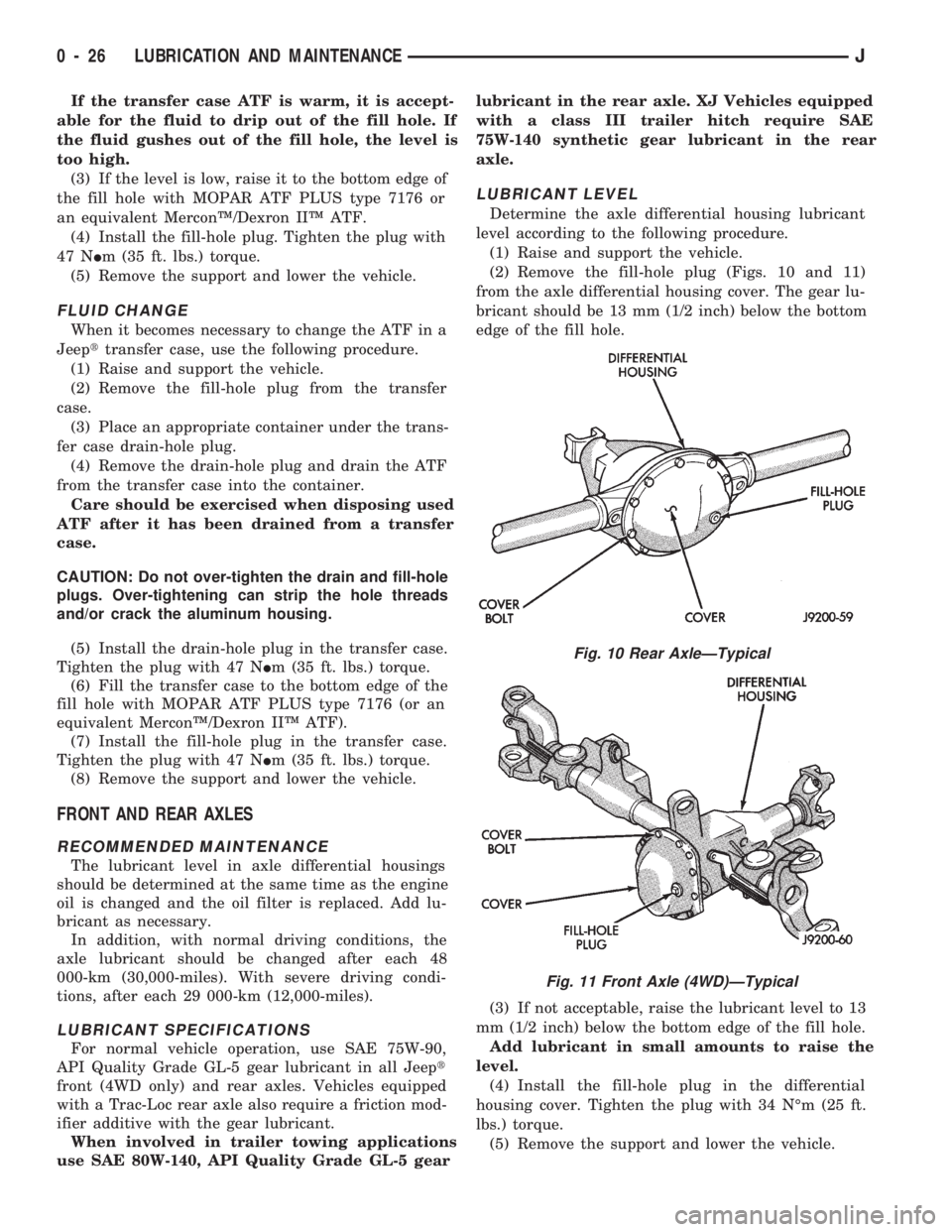
(2) Remove the fill-hole plug (Figs. 10 and 11)
from the axle differential housing cover. The gear lu-
bricant should be 13 mm (1/2 inch) below the bottom
edge of the fill hole.
(3) If not acceptable, raise the lubricant level to 13
mm (1/2 inch) below the bottom edge of the fill hole.
Add lubricant in small amounts to raise the
level.
(4) Install the fill-hole plug in the differential
housing cover. Tighten the plug with 34 NÉm (25 ft.
lbs.) torque.
(5) Remove the support and lower the vehicle.
Fig. 10 Rear AxleÐTypical
Fig. 11 Front Axle (4WD)ÐTypical
0 - 26 LUBRICATION AND MAINTENANCEJ
Page 238 of 1784
ERASING TROUBLE CODES
After the problem has been repaired, the DRB scan
tool must be used to erase a DTC. Refer to the ap-
propriate Powertrain Diagnostic Procedures service
manual for operation of the DRB scan tool.
DRB SCAN TOOL
For operation of the DRB scan tool, refer to the ap-
propriate Powertrain Diagnostic Procedures service
manual.
PRELIMINARY CHECKS
ENGINE COOLING SYSTEM OVERHEATING
Establish what driving conditions caused the com-
plaint. Abnormal loads on the cooling system such as
the following may be the cause.
1. PROLONGED IDLE, VERY HIGH AMBI-
ENT TEMPERATURE, SLIGHT TAIL WIND AT
IDLE, SLOW TRAFFIC, TRAFFIC JAMS, HIGH
SPEED, OR STEEP GRADES:
Driving techniques that avoid overheating are:
²Idle with A/C off when temperature gauge is at
end of normal range.
²Increasing engine speed for more air flow is recom-
mended.2. TRAILER TOWING:
Consult Trailer Towing section of owners manual.
Do not exceed limits.
3. AIR CONDITIONING; ADD-ON OR AFTER
MARKET:
A maximum cooling package should have been or-
dered with vehicle if add-on or after market A/C is
installed. If not, maximum cooling system compo-
nents should be installed for model involved per
manufacturer's specifications.
4. RECENT SERVICE OR ACCIDENT RE-
PAIR:
Determine if any recent service has been performed
on vehicle that may effect cooling system. This may
be:
²Engine adjustments (incorrect timing)
²Slipping engine accessory drive belt(s)
²Brakes (possibly dragging)
²Changed parts (incorrect water pump rotating in
wrong direction)
²Reconditioned radiator or cooling system refilling
(possibly under-filled or air trapped in system).
If investigation reveals none of the above as a
cause for engine overheating complaint, refer to fol-
lowing Symptom and Action chart.
JCOOLING SYSTEM 7 - 5
Page 518 of 1784
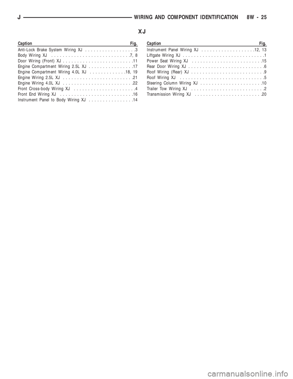
XJ
Caption Fig.
Anti-Lock Brake System Wiring XJ..................3
Body Wiring XJ............................7,8
Door Wiring (Front) XJ.........................11
Engine Compartment Wiring 2.5L XJ................17
Engine Compartment Wiring 4.0L XJ.............18, 19
Engine Wiring 2.5L XJ.........................21
Engine Wiring 4.0L XJ.........................22
Front Cross-body Wiring XJ......................4
Front End Wiring XJ..........................16
Instrument Panel to Body Wiring XJ................14Caption Fig.
Instrument Panel Wiring XJ...................12, 13
Liftgate Wiring XJ.............................1
Power Seat Wiring XJ.........................15
Rear Door Wiring XJ...........................6
Roof Wiring (Rear) XJ..........................9
Roof Wiring XJ..............................5
Steering Column Wiring XJ......................10
Trailer Tow Wiring XJ..........................2
Transmission Wiring XJ........................20
JWIRING AND COMPONENT IDENTIFICATION 8W - 25
Page 519 of 1784
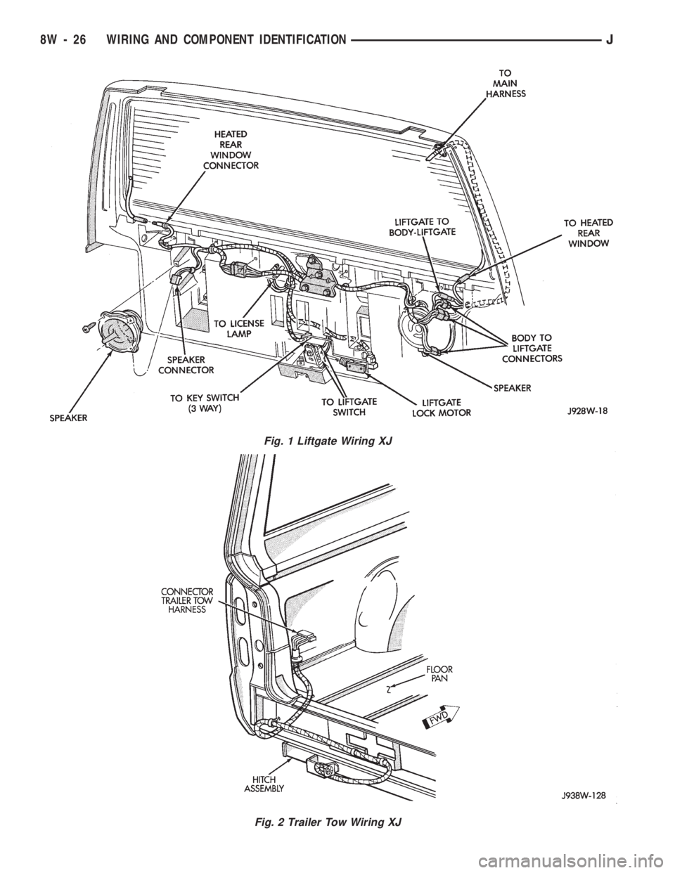
Fig. 1 Liftgate Wiring XJ
Fig. 2 Trailer Tow Wiring XJ
8W - 26 WIRING AND COMPONENT IDENTIFICATIONJ
Page 642 of 1784
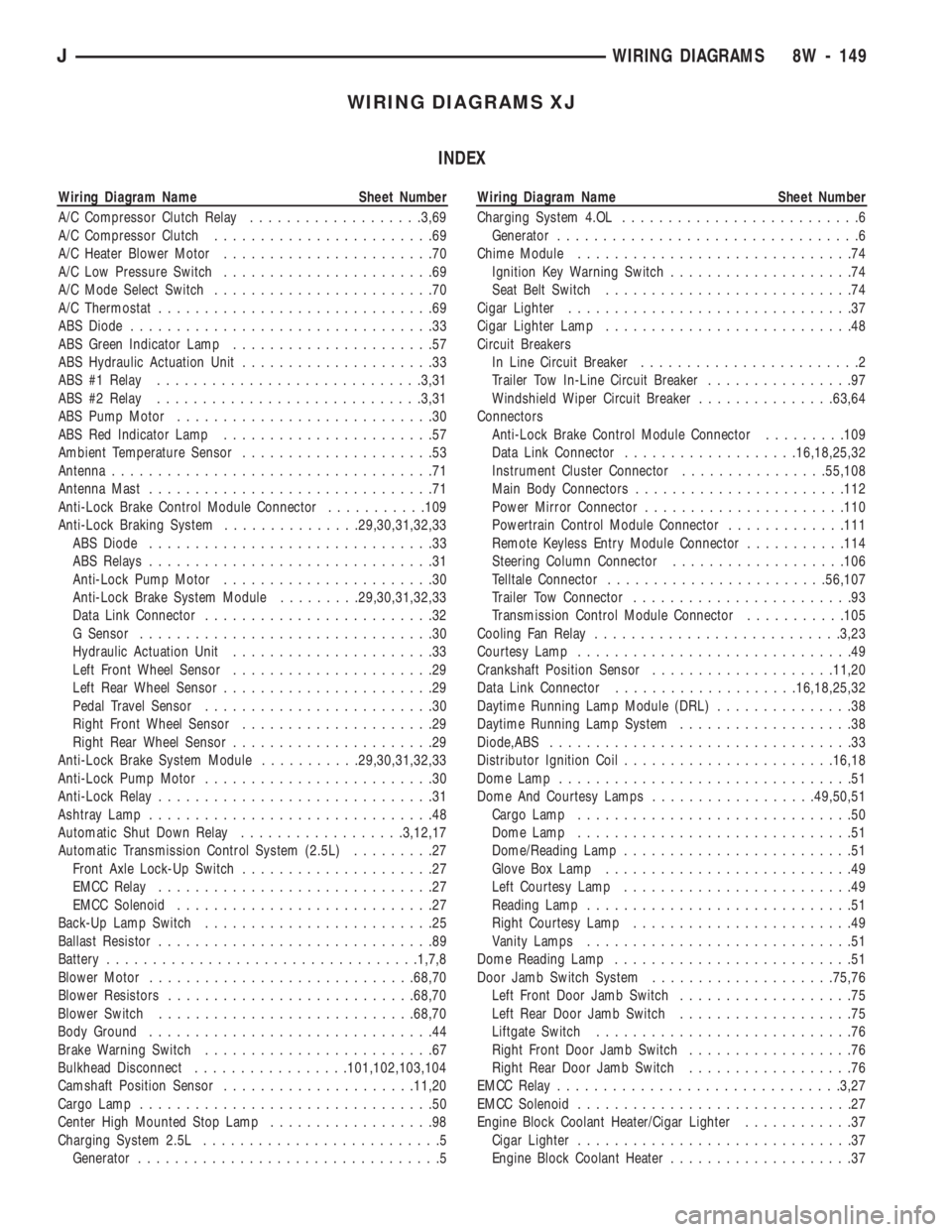
WIRING DIAGRAMS XJ
INDEX
Wiring Diagram Name Sheet Number
A/C Compressor Clutch Relay...................3,69
A/C Compressor Clutch........................69
A/C Heater Blower Motor.......................70
A/C Low Pressure Switch.......................69
A/C Mode Select Switch........................70
A/C Thermostat..............................69
ABS Diode.................................33
ABS Green Indicator Lamp......................57
ABS Hydraulic Actuation Unit.....................33
ABS #1 Relay.............................3,31
ABS #2 Relay.............................3,31
ABS Pump Motor............................30
ABS Red Indicator Lamp.......................57
Ambient Temperature Sensor.....................53
Antenna...................................71
Antenna Mast...............................71
Anti-Lock Brake Control Module Connector...........109
Anti-Lock Braking System...............29,30,31,32,33
ABS Diode...............................33
ABS Relays...............................31
Anti-Lock Pump Motor.......................30
Anti-Lock Brake System Module.........29,30,31,32,33
Data Link Connector.........................32
G Sensor................................30
Hydraulic Actuation Unit......................33
Left Front Wheel Sensor......................29
Left Rear Wheel Sensor.......................29
Pedal Travel Sensor.........................30
Right Front Wheel Sensor.....................29
Right Rear Wheel Sensor......................29
Anti-Lock Brake System Module...........29,30,31,32,33
Anti-Lock Pump Motor.........................30
Anti-Lock Relay..............................31
Ashtray Lamp...............................48
Automatic Shut Down Relay..................3,12,17
Automatic Transmission Control System (2.5L).........27
Front Axle Lock-Up Switch.....................27
EMCC Relay..............................27
EMCC Solenoid............................27
Back-Up Lamp Switch.........................25
Ballast Resistor..............................89
Battery..................................1,7,8
Blower Motor.............................68,70
Blower Resistors...........................68,70
Blower Switch............................68,70
Body Ground...............................44
Brake Warning Switch.........................67
Bulkhead Disconnect.................101,102,103,104
Camshaft Position Sensor.....................11,20
Cargo Lamp................................50
Center High Mounted Stop Lamp..................98
Charging System 2.5L..........................5
Generator.................................5Wiring Diagram Name Sheet Number
Charging System 4.OL..........................6
Generator.................................6
Chime Module..............................74
Ignition Key Warning Switch....................74
Seat Belt Switch...........................74
Cigar Lighter...............................37
Cigar Lighter Lamp...........................48
Circuit Breakers
In Line Circuit Breaker........................2
Trailer Tow In-Line Circuit Breaker................97
Windshield Wiper Circuit Breaker...............63,64
Connectors
Anti-Lock Brake Control Module Connector.........109
Data Link Connector...................16,18,25,32
Instrument Cluster Connector................55,108
Main Body Connectors.......................112
Power Mirror Connector......................110
Powertrain Control Module Connector.............111
Remote Keyless Entry Module Connector...........114
Steering Column Connector...................106
Telltale Connector........................56,107
Trailer Tow Connector........................93
Transmission Control Module Connector...........105
Cooling Fan Relay...........................3,23
Courtesy Lamp..............................49
Crankshaft Position Sensor....................11,20
Data Link Connector....................16,18,25,32
Daytime Running Lamp Module (DRL)...............38
Daytime Running Lamp System...................38
Diode,ABS.................................33
Distributor Ignition Coil.......................16,18
Dome Lamp................................51
Dome And Courtesy Lamps..................49,50,51
Cargo Lamp..............................50
Dome Lamp..............................51
Dome/Reading Lamp.........................51
Glove Box Lamp...........................49
Left Courtesy Lamp.........................49
Reading Lamp.............................51
Right Courtesy Lamp........................49
Vanity Lamps.............................51
Dome Reading Lamp..........................51
Door Jamb Switch System....................75,76
Left Front Door Jamb Switch...................75
Left Rear Door Jamb Switch...................75
Liftgate Switch............................76
Right Front Door Jamb Switch..................76
Right Rear Door Jamb Switch..................76
EMCC Relay...............................3,27
EMCC Solenoid..............................27
Engine Block Coolant Heater/Cigar Lighter............37
Cigar Lighter..............................37
Engine Block Coolant Heater....................37
JWIRING DIAGRAMS 8W - 149