1994 JEEP CHEROKEE center console
[x] Cancel search: center consolePage 310 of 1784
circles, in not less than 48 seconds. The CAL light
will go off and the compass is now calibrated.
(5) Reset variation number. This step must be
done every time step 2 is performed.
If CAL light does not go off, either there is ex-
cessive magnetism near the compass or the unit
is defective. Repeat the degaussing and calibra-
tion procedures at least one more time.
If the wrong direction is still indicated, the
area selected may be too close to a magnetic
source. Repeat the calibration procedure in an-
other location.
DEGAUSSING PROCEDURE
The tool used to degauss or demagnetize the forward
console attaching screw and roof panel is the Miller
Tool 6029. Equivalent units must be rated as continu-
ous duty for 110/115 volts, 60Hz with a field strength of
over 350 gauss at 1/4 inch beyond the tip of the probe.
In this degaussing procedure the degaussing tool is
used to demagnetize both the roof panel and console
forward mounting screw.
(1) Be sure the ignition switch is in the OFF posi-
tion before you begin the degaussing procedures.
CAUTION: Keep the degaussing tool at least 2 inches
away from the compass area when plugging it in.
(2) Plug the degaussing tool into a standard
110/115 volt AC outlet.
CONSOLE FORWARD MOUNTING SCREW
(3) Slowly approach the head of the forward
mounting screw with the plastic coated tip of the de-
gaussing tool. Contact the head of the screw for
about two seconds.
(4) With the degaussing tool still energized, slowly
back it away from the screw until the tool is at least
2 inches from the screw head then unplug the tool.
ROOF PANEL
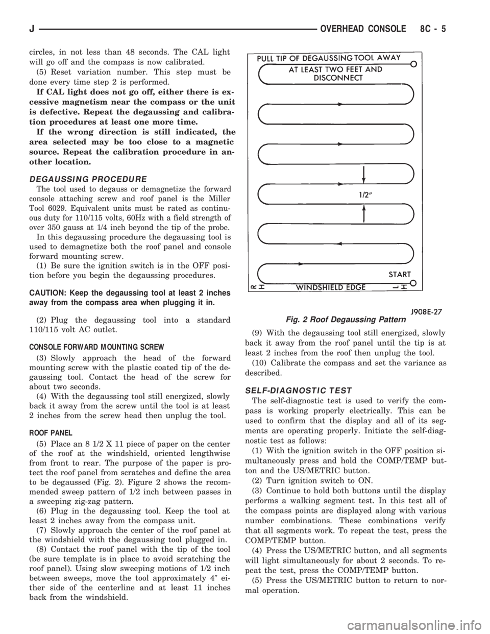
(5) Place an 8 1/2 X 11 piece of paper on the center
of the roof at the windshield, oriented lengthwise
from front to rear. The purpose of the paper is pro-
tect the roof panel from scratches and define the area
to be degaussed (Fig. 2). Figure 2 shows the recom-
mended sweep pattern of 1/2 inch between passes in
a sweeping zig-zag pattern.
(6) Plug in the degaussing tool. Keep the tool at
least 2 inches away from the compass unit.
(7) Slowly approach the center of the roof panel at
the windshield with the degaussing tool plugged in.
(8) Contact the roof panel with the tip of the tool
(be sure template is in place to avoid scratching the
roof panel). Using slow sweeping motions of 1/2 inch
between sweeps, move the tool approximately 49ei-
ther side of the centerline and at least 11 inches
back from the windshield.(9) With the degaussing tool still energized, slowly
back it away from the roof panel until the tip is at
least 2 inches from the roof then unplug the tool.
(10) Calibrate the compass and set the variance as
described.
SELF-DIAGNOSTIC TEST
The self-diagnostic test is used to verify the com-
pass is working properly electrically. This can be
used to confirm that the display and all of its seg-
ments are operating properly. Initiate the self-diag-
nostic test as follows:
(1) With the ignition switch in the OFF position si-
multaneously press and hold the COMP/TEMP but-
ton and the US/METRIC button.
(2) Turn ignition switch to ON.
(3) Continue to hold both buttons until the display
performs a walking segment test. In this test all of
the compass points are displayed along with various
number combinations. These combinations verify
that all segments work. To repeat the test, press the
COMP/TEMP button.
(4) Press the US/METRIC button, and all segments
will light simultaneously for about 2 seconds. To re-
peat the test, press the COMP/TEMP button.
(5) Press the US/METRIC button to return to nor-
mal operation.
Fig. 2 Roof Degaussing Pattern
JOVERHEAD CONSOLE 8C - 5
Page 311 of 1784
(6) Should any segment in any of the digit positions
fail to light, the unit is defective and should be re-
placed.
THERMOMETER AND SENSOR SYSTEM REPAIR
PROCEDURES
This portion of the display consists of a sensor, the
circuit and display devoted to the temperature mea-
suring and display. The sensor is mounted at the
center of the vehicle below the grille, behind the
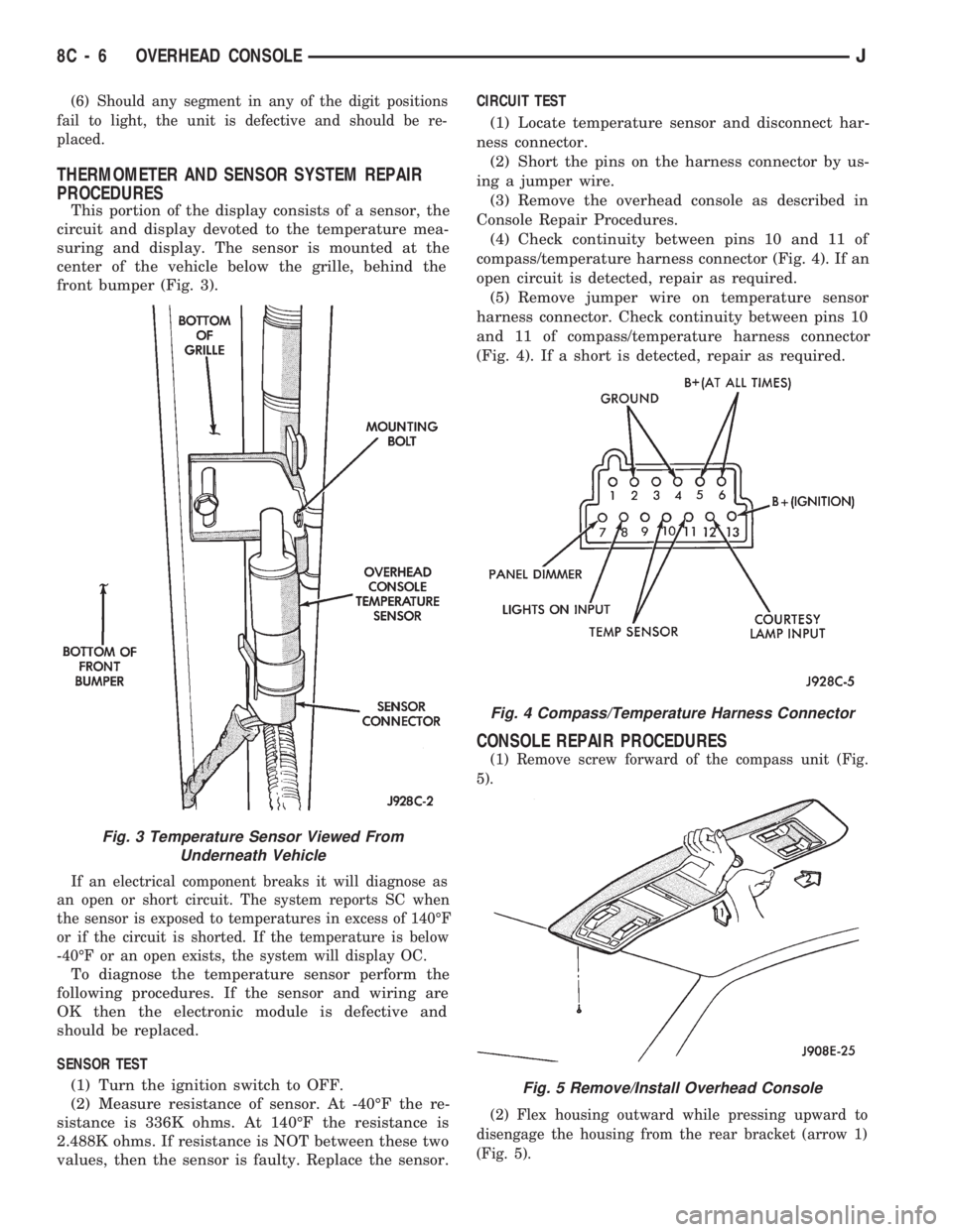
front bumper (Fig. 3).
If an electrical component breaks it will diagnose as
an open or short circuit. The system reports SC when
the sensor is exposed to temperatures in excess of 140ÉF
or if the circuit is shorted. If the temperature is below
-40ÉF or an open exists, the system will display OC.
To diagnose the temperature sensor perform the
following procedures. If the sensor and wiring are
OK then the electronic module is defective and
should be replaced.
SENSOR TEST
(1) Turn the ignition switch to OFF.
(2) Measure resistance of sensor. At -40ÉF the re-
sistance is 336K ohms. At 140ÉF the resistance is
2.488K ohms. If resistance is NOT between these two
values, then the sensor is faulty. Replace the sensor.CIRCUIT TEST
(1) Locate temperature sensor and disconnect har-
ness connector.
(2) Short the pins on the harness connector by us-
ing a jumper wire.
(3) Remove the overhead console as described in
Console Repair Procedures.
(4) Check continuity between pins 10 and 11 of
compass/temperature harness connector (Fig. 4). If an
open circuit is detected, repair as required.
(5) Remove jumper wire on temperature sensor
harness connector. Check continuity between pins 10
and 11 of compass/temperature harness connector
(Fig. 4). If a short is detected, repair as required.
CONSOLE REPAIR PROCEDURES
(1) Remove screw forward of the compass unit (Fig.
5).
(2) Flex housing outward while pressing upward to
disengage the housing from the rear bracket (arrow 1)
(Fig. 5).
Fig. 4 Compass/Temperature Harness Connector
Fig. 5 Remove/Install Overhead Console
Fig. 3 Temperature Sensor Viewed From
Underneath Vehicle
8C - 6 OVERHEAD CONSOLEJ
Page 313 of 1784
SUNGLASS BIN AND SPRING ASSEMBLY
(1) Open sunglass bin door.
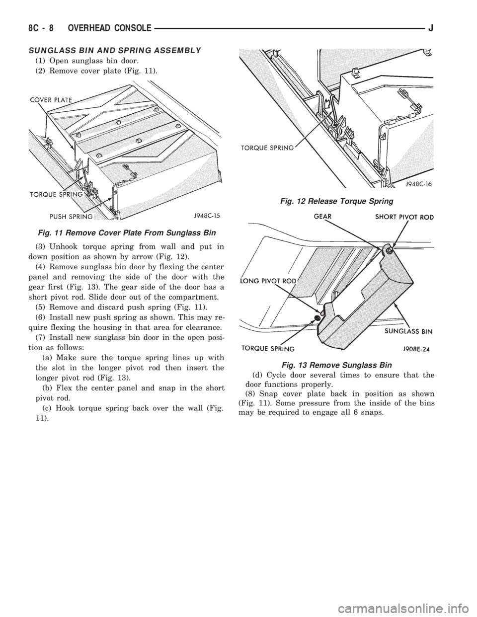
(2) Remove cover plate (Fig. 11).
(3) Unhook torque spring from wall and put in
down position as shown by arrow (Fig. 12).
(4) Remove sunglass bin door by flexing the center
panel and removing the side of the door with the
gear first (Fig. 13). The gear side of the door has a
short pivot rod. Slide door out of the compartment.
(5) Remove and discard push spring (Fig. 11).
(6) Install new push spring as shown. This may re-
quire flexing the housing in that area for clearance.
(7) Install new sunglass bin door in the open posi-
tion as follows:
(a) Make sure the torque spring lines up with
the slot in the longer pivot rod then insert the
longer pivot rod (Fig. 13).
(b) Flex the center panel and snap in the short
pivot rod.
(c) Hook torque spring back over the wall (Fig.
11).(d) Cycle door several times to ensure that the
door functions properly.
(8) Snap cover plate back in position as shown
(Fig. 11). Some pressure from the inside of the bins
may be required to engage all 6 snaps.
Fig. 11 Remove Cover Plate From Sunglass Bin
Fig. 12 Release Torque Spring
Fig. 13 Remove Sunglass Bin
8C - 8 OVERHEAD CONSOLEJ
Page 467 of 1784
(7) Remove screw and printed circuit board.
(8) To install the overhead console, reverse the re-
moval procedures. Be sure to flex housing outward
near the keyless entry receiver until the console
snaps onto the rear mounting bracket.
WITHOUT OVERHEAD CONSOLE
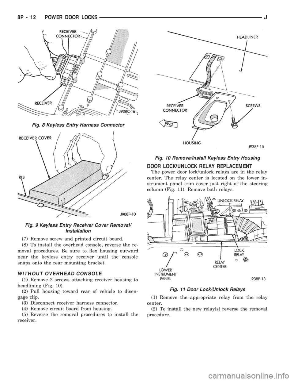
(1) Remove 2 screws attaching receiver housing to
headlining (Fig. 10).
(2) Pull housing toward rear of vehicle to disen-
gage clip.
(3) Disconnect receiver harness connector.
(4) Remove circuit board from housing.
(5) Reverse the removal procedures to install the
receiver.
DOOR LOCK/UNLOCK RELAY REPLACEMENT
The power door lock/unlock relays are in the relay
center. The relay center is located on the lower in-
strument panel trim cover just right of the steering
column (Fig. 11). Remove both relays.
(1) Remove the appropriate relay from the relay
center.
(2) To install the new relay(s) reverse the removal
procedure.
Fig. 8 Keyless Entry Harness Connector
Fig. 9 Keyless Entry Receiver Cover Removal/
Installation
Fig. 10 Remove/Install Keyless Entry Housing
Fig. 11 Door Lock/Unlock Relays
8P - 12 POWER DOOR LOCKSJ
Page 485 of 1784
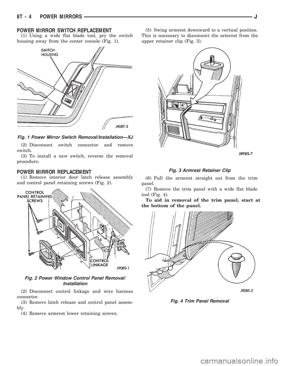
POWER MIRROR SWITCH REPLACEMENT
(1) Using a wide flat blade tool, pry the switch
housing away from the center console (Fig. 1).
(2) Disconnect switch connector and remove
switch.
(3) To install a new switch, reverse the removal
procedure.
POWER MIRROR REPLACEMENT
(1) Remove interior door latch release assembly
and control panel retaining screws (Fig. 2).
(2) Disconnect control linkage and wire harness
connector.
(3) Remove latch release and control panel assem-
bly.
(4) Remove armrest lower retaining screws.(5) Swing armrest downward to a vertical position.
This is necessary to disconnect the armrest from the
upper retainer clip (Fig. 3).
(6) Pull the armrest straight out from the trim
panel.
(7) Remove the trim panel with a wide flat blade
tool (Fig. 4).
To aid in removal of the trim panel, start at
the bottom of the panel.
Fig. 1 Power Mirror Switch Removal/InstallationÐXJ
Fig. 2 Power Window Control Panel Removal/
Installation
Fig. 3 Armrest Retainer Clip
Fig. 4 Trim Panel Removal
8T - 4 POWER MIRRORSJ
Page 645 of 1784
Wiring Diagram Name Sheet Number
License Lamp...........................91,95
Low Washer Indicator Lamp..................57,58
Malfunction Indicator Lamp..................57,58
Maintenance Required Indicator Lamp...........57,58
Park Brake Indicator Lamp.....................58
Reading Lamp.............................51
Rear Wiper/Wash Switch Lamp..................47
Right Back-Up Lamp.......................92,96
Right Courtesy Lamp........................49
Right Fog Lamp............................40
Right Headlamp............................40
Right Park/Turn Signal Lamp...................40
Right Side Marker Lamp (Front).................40
Right Side Marker (Rear)....................92,96
Right Tail/Stop Lamp......................92,96
Right Turn Indicator Lamp.................59,60,61
Right Turn Lamp (Amber)...................92,96
Right Vanity Lamp..........................51
Seat Belt Warning Indicator Lamp..............57,58
Transfer Case Lamp.........................48
Transmission Range Switch Lamp................48
Underhood Lamp...........................34
Upshift Indicator Lamp.....................57,58
Vanity Lamps...........................51,53
L.C.D. Illumination Relay........................52
Left Front Door Connector And Door Lock Switch
Function Chart.............................87
Left Front Door Connector and Widow Lift Switch
Function Chart.............................87
Left Front Door Jamb Switch.....................75
Left Front Door Lock Motor......................86
Left Front Door Speaker........................71
Left Front Wheel Sensor........................29
Left Instrument Panel Speaker....................71
Left Liftgate Speaker..........................72
Left Power Seat Motor Assembly..................77
Left Power Seat Switch........................77
Left Rear Door Connector and Window Lift Switch
Function Chart.............................88
Left Rear Door Jamb Switch.....................75
Left Rear Door Window Switch...................82
Left Rear Wheel Sensor........................29
Left Turn Relay..............................97
Liftgate Switch..............................76
Liftgate Lock motor...........................86
Lo-Line Instrument Cluster Printed Circuit Board........60
Low Fuel Warning Module...................59,60,61
Low Washer Indicator Lamp...................57,58
Main Body Connectors........................112
Maintenance Required Indicator Lamp.............57,58
Malfunction Indicator Lamp....................57,58
Map Sensor..............................14,19
Modules
Anti-Lock Brake System Module.........29,30,31,32,33
Chime Module.............................74
Daytime Running Lamp Module.................38
Headlamp Delay Module......................43
Intermittent Wiper Module.....................64Wiring Diagram Name Sheet Number
Low Fuel Warning Module.................59,60,61
Powertrain Control Module. . . .11,12,13,14,15,16,17, 18,19,
20,21,22,23,35,36,45,55,69
Remote Keyless Entry Module...................28
Transmission Control Module.................25,26
Motors
ABS Pump Motor...........................30
A/C Heater Blower Motor......................70
Engine Starter Motor........................7,8
Front Wiper Motor........................63,64
Heater Blower Motor.........................68
Idle Air Control Motor......................15,22
Left Front Door Lock Motor....................86
Left Front Door Window Motor..................81
Left Power Mirror..........................73
Left Power Seat Motor Assembly................77
Left Rear Door Lock Motor....................86
Left Rear Door Window Motor..................82
Liftgate Lock Motor.........................86
Radiator Fan Motor.........................23
Rear Wiper Motor..........................65
Right Front Door Lock Motor...................86
Right Front Door Window Motor.................81
Right Power Mirror.........................73
Right Rear Door Lock Motor...................86
Right Rear Door Window Motor.................82
Oil Pressure Switch...........................24
Overhead Console System.....................53,54
Ambient Temperature Sensor...................53
Overhead Console..........................53
Vanity Lamps.............................53
Park Brake Switch............................67
Park Brake Indicator Lamp......................58
Parking Brake Switch..........................67
Park Lamp Relay.............................39
Park/Neutral Position Switch......................7
Pedal Travel Sensor...........................30
Power Distribution Center....................1,2,3,4
Power Distribution Center Application Chart............4
Power Distribution Center Identification...............3
Power Door Locks......................83,84,85,86
Left Door Lock Switch.......................85
Left Front Door Lock Motor....................86
Left Rear Door Lock Motor....................86
Liftgate Lock Motor.........................86
Power Door Lock Relay.......................83
Power Door Unlock Relay.....................83
Right Door Lock Switch......................85
Right Front Door Lock Motor...................86
Right Rear Door Lock Motor...................86
Power Door Lock Relay........................83
Power Door Unlock Relay.......................83
Power Mirror Connector.......................110
Power Mirror Connector and Switch Function Chart......88
Power Mirror Switch Assembly...................73
Power Mirror System..........................73
Left Power Mirror..........................73
Power Mirror Switch Assembly..................73
8W - 152 WIRING DIAGRAMSJ
Page 1083 of 1784
(3) Remove the steering column mounting bracket
to instrument panel nuts. Lower the steering column.
Refer to Steering Column Removal .
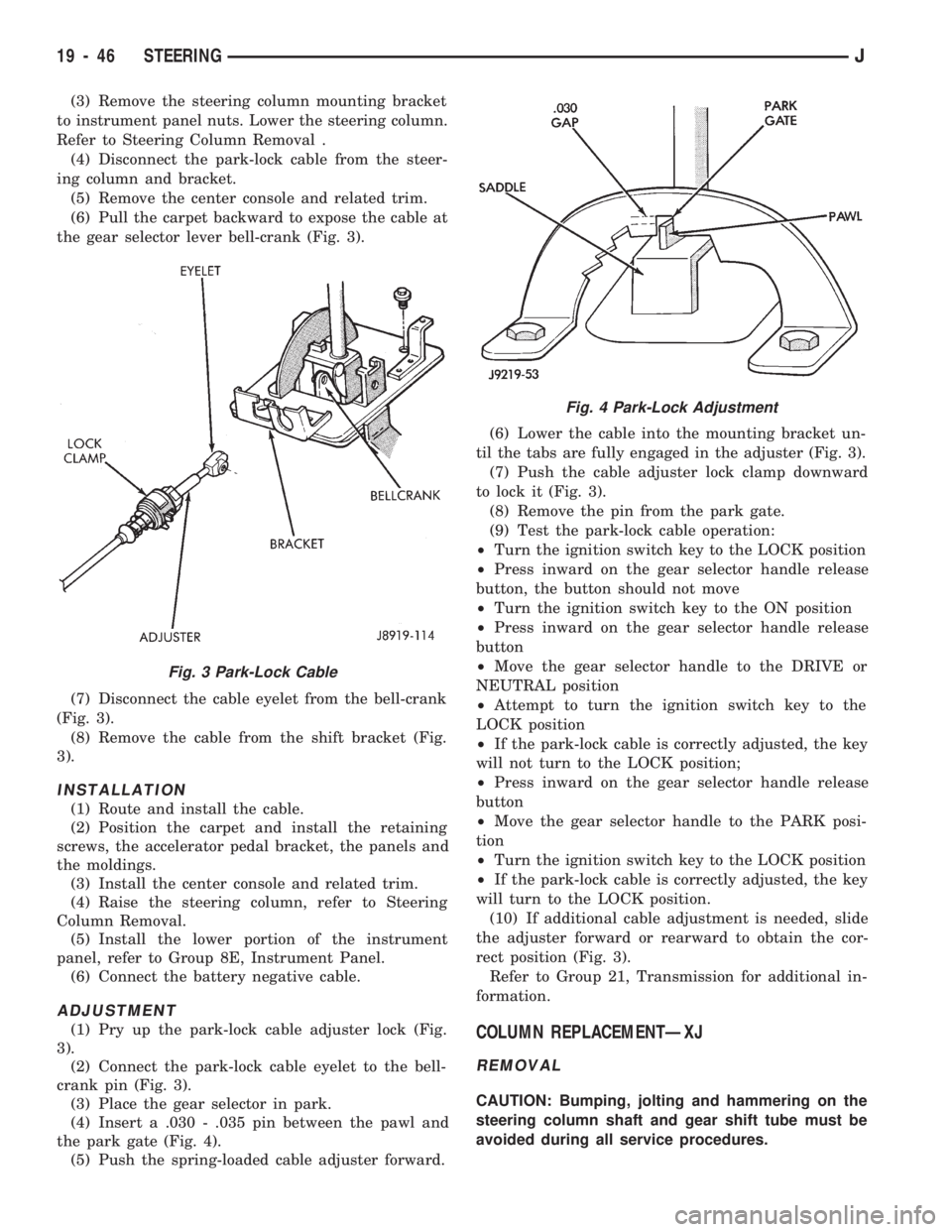
(4) Disconnect the park-lock cable from the steer-
ing column and bracket.
(5) Remove the center console and related trim.
(6) Pull the carpet backward to expose the cable at
the gear selector lever bell-crank (Fig. 3).
(7) Disconnect the cable eyelet from the bell-crank
(Fig. 3).
(8) Remove the cable from the shift bracket (Fig.
3).
INSTALLATION
(1) Route and install the cable.
(2) Position the carpet and install the retaining
screws, the accelerator pedal bracket, the panels and
the moldings.
(3) Install the center console and related trim.
(4) Raise the steering column, refer to Steering
Column Removal.
(5) Install the lower portion of the instrument
panel, refer to Group 8E, Instrument Panel.
(6) Connect the battery negative cable.
ADJUSTMENT
(1) Pry up the park-lock cable adjuster lock (Fig.
3).
(2) Connect the park-lock cable eyelet to the bell-
crank pin (Fig. 3).
(3) Place the gear selector in park.
(4) Insert a .030 - .035 pin between the pawl and
the park gate (Fig. 4).
(5) Push the spring-loaded cable adjuster forward.(6) Lower the cable into the mounting bracket un-
til the tabs are fully engaged in the adjuster (Fig. 3).
(7) Push the cable adjuster lock clamp downward
to lock it (Fig. 3).
(8) Remove the pin from the park gate.
(9) Test the park-lock cable operation:
²Turn the ignition switch key to the LOCK position
²Press inward on the gear selector handle release
button, the button should not move
²Turn the ignition switch key to the ON position
²Press inward on the gear selector handle release
button
²Move the gear selector handle to the DRIVE or
NEUTRAL position
²Attempt to turn the ignition switch key to the
LOCK position
²If the park-lock cable is correctly adjusted, the key
will not turn to the LOCK position;
²Press inward on the gear selector handle release
button
²Move the gear selector handle to the PARK posi-
tion
²Turn the ignition switch key to the LOCK position
²If the park-lock cable is correctly adjusted, the key
will turn to the LOCK position.
(10) If additional cable adjustment is needed, slide
the adjuster forward or rearward to obtain the cor-
rect position (Fig. 3).
Refer to Group 21, Transmission for additional in-
formation.COLUMN REPLACEMENTÐXJ
REMOVAL
CAUTION: Bumping, jolting and hammering on the
steering column shaft and gear shift tube must be
avoided during all service procedures.
Fig. 3 Park-Lock Cable
Fig. 4 Park-Lock Adjustment
19 - 46 STEERINGJ
Page 1103 of 1784
(33 in. lbs.) torque. Thread the hazard warning
switch knob into the switch and pull the knob out-
ward.
(38) Install and seat the upper bearing race in the
key/lock cylinder housing.
(39) Install the upper bearing preload spring, the
canceling cam and the lockplate.
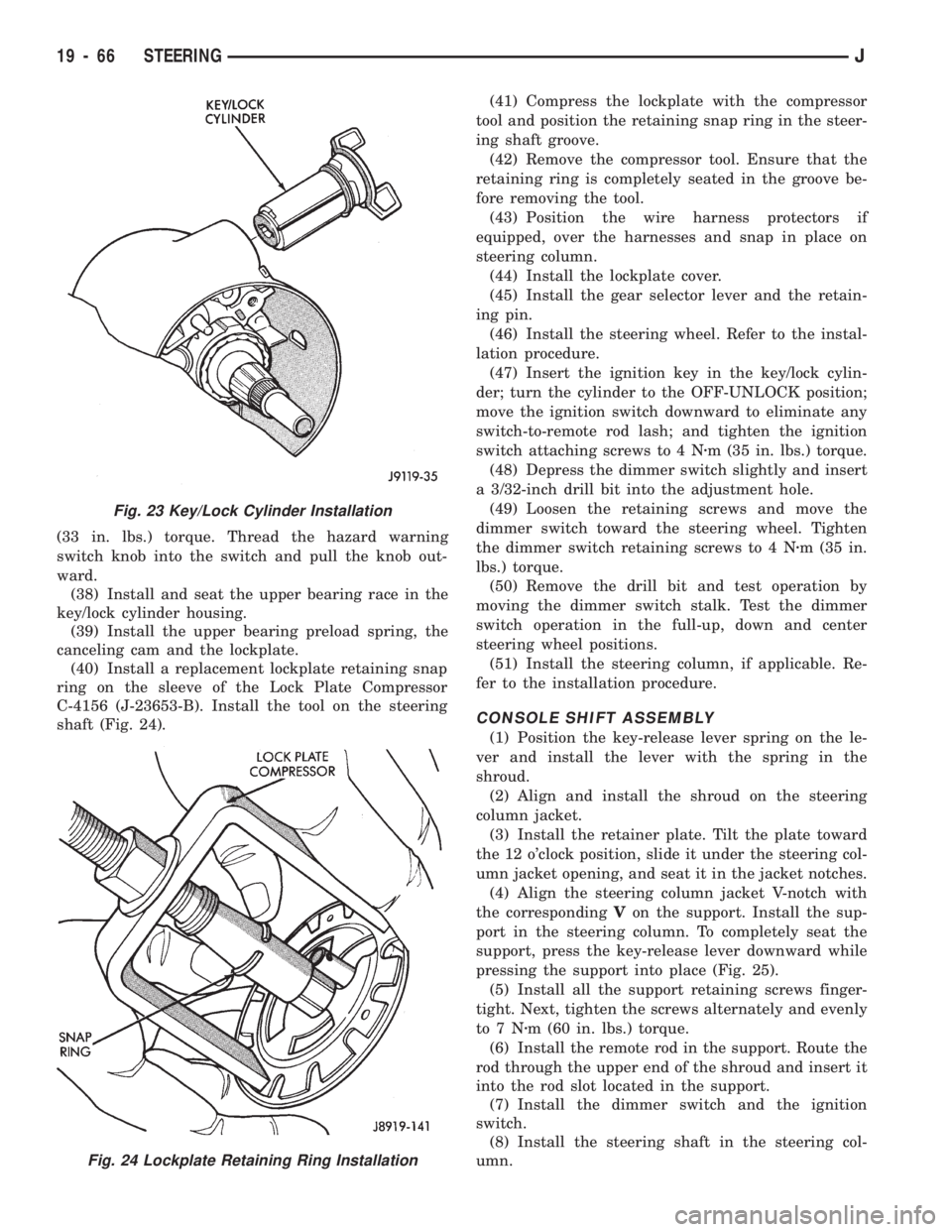
(40) Install a replacement lockplate retaining snap
ring on the sleeve of the Lock Plate Compressor
C-4156 (J-23653-B). Install the tool on the steering
shaft (Fig. 24).(41) Compress the lockplate with the compressor
tool and position the retaining snap ring in the steer-
ing shaft groove.
(42) Remove the compressor tool. Ensure that the
retaining ring is completely seated in the groove be-
fore removing the tool.
(43) Position the wire harness protectors if
equipped, over the harnesses and snap in place on
steering column.
(44) Install the lockplate cover.
(45) Install the gear selector lever and the retain-
ing pin.
(46) Install the steering wheel. Refer to the instal-
lation procedure.
(47) Insert the ignition key in the key/lock cylin-
der; turn the cylinder to the OFF-UNLOCK position;
move the ignition switch downward to eliminate any
switch-to-remote rod lash; and tighten the ignition
switch attaching screws to 4 Nzm (35 in. lbs.) torque.
(48) Depress the dimmer switch slightly and insert
a 3/32-inch drill bit into the adjustment hole.
(49) Loosen the retaining screws and move the
dimmer switch toward the steering wheel. Tighten
the dimmer switch retaining screws to 4 Nzm (35 in.
lbs.) torque.
(50) Remove the drill bit and test operation by
moving the dimmer switch stalk. Test the dimmer
switch operation in the full-up, down and center
steering wheel positions.
(51) Install the steering column, if applicable. Re-
fer to the installation procedure.
CONSOLE SHIFT ASSEMBLY
(1) Position the key-release lever spring on the le-
ver and install the lever with the spring in the
shroud.
(2) Align and install the shroud on the steering
column jacket.
(3) Install the retainer plate. Tilt the plate toward
the 12 o'clock position, slide it under the steering col-
umn jacket opening, and seat it in the jacket notches.
(4) Align the steering column jacket V-notch with
the correspondingVon the support. Install the sup-
port in the steering column. To completely seat the
support, press the key-release lever downward while
pressing the support into place (Fig. 25).
(5) Install all the support retaining screws finger-
tight. Next, tighten the screws alternately and evenly
to7Nzm (60 in. lbs.) torque.
(6) Install the remote rod in the support. Route the
rod through the upper end of the shroud and insert it
into the rod slot located in the support.
(7) Install the dimmer switch and the ignition
switch.
(8) Install the steering shaft in the steering col-
umn.
Fig. 23 Key/Lock Cylinder Installation
Fig. 24 Lockplate Retaining Ring Installation
19 - 66 STEERINGJ