1994 JEEP CHEROKEE wiring
[x] Cancel search: wiringPage 66 of 1784
SHIFT MOTOR Ð REMOVAL/DISASSEMBLY
(1) Disconnect the vacuum and wiring connector
from the shift housing.
(2) Remove indicator switch.
(3) Remove the shift motor housing cover, gasket
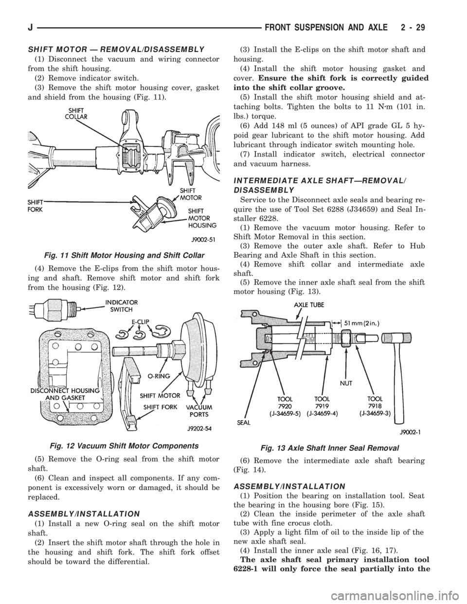
and shield from the housing (Fig. 11).
(4) Remove the E-clips from the shift motor hous-
ing and shaft. Remove shift motor and shift fork
from the housing (Fig. 12).
(5) Remove the O-ring seal from the shift motor
shaft.
(6) Clean and inspect all components. If any com-
ponent is excessively worn or damaged, it should be
replaced.
ASSEMBLY/INSTALLATION
(1) Install a new O-ring seal on the shift motor
shaft.
(2) Insert the shift motor shaft through the hole in
the housing and shift fork. The shift fork offset
should be toward the differential.(3) Install the E-clips on the shift motor shaft and
housing.
(4) Install the shift motor housing gasket and
cover.Ensure the shift fork is correctly guided
into the shift collar groove.
(5) Install the shift motor housing shield and at-
taching bolts. Tighten the bolts to 11 Nzm (101 in.
lbs.) torque.
(6) Add 148 ml (5 ounces) of API grade GL 5 hy-
poid gear lubricant to the shift motor housing. Add
lubricant through indicator switch mounting hole.
(7) Install indicator switch, electrical connector
and vacuum harness.
INTERMEDIATE AXLE SHAFTÐREMOVAL/
DISASSEMBLY
Service to the Disconnect axle seals and bearing re-
quire the use of Tool Set 6288 (J34659) and Seal In-
staller 6228.
(1) Remove the vacuum motor housing. Refer to
Shift Motor Removal in this section.
(3) Remove the outer axle shaft. Refer to Hub
Bearing and Axle Shaft in this section.
(4) Remove shift collar and intermediate axle
shaft.
(5) Remove the inner axle shaft seal from the shift
motor housing (Fig. 13).
(6) Remove the intermediate axle shaft bearing
(Fig. 14).
ASSEMBLY/INSTALLATION
(1) Position the bearing on installation tool. Seat
the bearing in the housing bore (Fig. 15).
(2) Clean the inside perimeter of the axle shaft
tube with fine crocus cloth.
(3) Apply a light film of oil to the inside lip of the
new axle shaft seal.
(4) Install the inner axle seal (Fig. 16, 17).
The axle shaft seal primary installation tool
6228-1 will only force the seal partially into the
Fig. 11 Shift Motor Housing and Shift Collar
Fig. 12 Vacuum Shift Motor ComponentsFig. 13 Axle Shaft Inner Seal Removal
JFRONT SUSPENSION AND AXLE 2 - 29
Page 106 of 1784

Refer to Group 8D, Ignition System for more crank-
shaft position sensor information.
The engine will not operate if the PCM does not re-
ceive a crankshaft position sensor input.
ENGINE COOLANT TEMPERATURE SENSORÐPCM
INPUT
The coolant temperature sensor is installed in the
thermostat housing (Fig. 10) and protrudes into the
water jacket. The sensor provides an input voltage to
the powertrain control module (PCM) relating cool-
ant temperature. The PCM uses this input along
with inputs from other sensors to determine injector
pulse width and ignition timing. As coolant temper-
ature varies, the coolant temperature sensor's resis-
tance changes. The change in resistance results in a
different input voltage to the PCM.
When the engine is cold, the PCM will operate in
Open Loop cycle. It will demand slightly richer air-
fuel mixtures and higher idle speeds. This is done
until normal operating temperatures are reached.
Refer to Open Loop/Closed Loop Modes of Opera-
tion in this section of the group for more information.
EXTENDED IDLE SWITCHÐPCM INPUT
OPTIONAL POLICE PACKAGE ONLY
The extended idle switch is used to raise the en-
gine idle speed to approximately 1000 rpm. This is
when the shifter is in either the Park or Neutral po-
sition. A rocker-type 2-wire switch (extended idle
switch) is mounted to the instrument panel. This
switch will supply a ground circuit to the powertrain
control module (PCM).The switch is available
only with 4.0L engine when supplied with the
optional police package.
For testing and diagnosis of this switch and its cir-
cuit, refer to the MFI SystemÐGeneral Diagnosis
section of this group.
IGNITION CIRCUIT SENSEÐPCM INPUT
The ignition circuit sense input tells the powertrain
control module (PCM) the ignition switch has ener-
gized the ignition circuit. Refer to the wiring dia-
grams for circuit information.
MANIFOLD ABSOLUTE PRESSURE (MAP)
SENSORÐPCM INPUT
The MAP sensor reacts to absolute pressure in the
intake manifold. It provides an input voltage to the
powertrain control module (PCM). As engine load
changes, manifold pressure varies. The change in
manifold pressure causes MAP sensor voltage to
change. The change in MAP sensor voltage results in
a different input voltage to the PCM. The input volt-
age level supplies the PCM with information about
ambient barometric pressure during engine start-up
(cranking) and engine load while the engine is run-
ning. The PCM uses this input along with inputs
from other sensors to adjust air-fuel mixture.
The MAP sensor is mounted on the dash panel.
The sensor is connected to the throttle body with a
vacuum hose and to the PCM electrically.
Fig. 8 Sensor LocationÐ4.0L Engine
Fig. 9 Sensor LocationÐ2.5L Engine
Fig. 10 Coolant Temperature SensorÐTypical
JFUEL SYSTEM 14 - 21
Page 110 of 1784

FUEL PUMP RELAYÐPCM OUTPUT
The PCM energizes the fuel pump through the fuel
pump relay. Battery voltage is applied to the relay
from the ignition switch. The relay is energized when
a ground is provided by the PCM. Refer to Automatic
Shut Down Relay for additional information.
FUEL INJECTORSÐPCM OUTPUT
Six individual fuel injectors are used with the 4.0L
6 cylinder engine. Four individual fuel injectors are
used with the 2.5L 4 cylinder engine. The injectors
are attached to the fuel rail (Fig. 19).
The nozzle ends of the injectors are positioned into
openings in the intake manifold just above the in-
take valve ports of the cylinder head. The engine
wiring harness connector for each fuel injector is
equipped with an attached numerical tag (INJ 1, INJ
2 etc.). This is used to identify each fuel injector.
The injectors are energized individually in a se-
quential order by the powertrain control module
(PCM). The PCM will adjust injector pulse width by
switching the ground path to each individual injector
on and off. Injector pulse width is the period of time
that the injector is energized. The PCM will adjust
injector pulse width based on various inputs it re-
ceives.
During start up, battery voltage is supplied to the
injectors through the ASD relay. When the engine is
operating, voltage is supplied by the charging sys-
tem. The PCM determines injector pulse width based
on various inputs.
GENERATOR FIELDÐPCM OUTPUT
The powertrain control module (PCM) regulates
the charging system voltage within a range of 12.9 to
15.0 volts. Refer to Group 8A for charging system in-
formation.
GENERATOR LAMPÐPCM OUTPUT
IF EQUIPPED
If the powertrain control module (PCM) senses a
low charging condition in the charging system, it
will illuminate the generator lamp on the instrument
panel. For example, during low idle with all accesso-
ries turned on, the light may momentarily go on.
Once the PCM corrects idle speed to a higher rpm,
the light will go out. Refer to Group 8A, Battery/
Starting/Charging Systems for charging system in-
formation.
IDLE AIR CONTROL (IAC) MOTORÐPCM OUTPUT
The IAC motor is mounted on the throttle body
(Figs. 20 or 21) and is controlled by the powertrain
control module (PCM).
The throttle body has an air control passage that
provides air for the engine at idle (the throttle plate
is closed). The IAC motor pintle protrudes into the
air control passage and regulates air flow through it.
Based on various sensor inputs, the powertrain con-
trol module (PCM) adjusts engine idle speed by mov-
Fig. 19 Fuel InjectorsÐTypical
Fig. 20 IAC MotorÐ4.0L Engine
Fig. 21 IAC MotorÐ2.5L Engine
JFUEL SYSTEM 14 - 25
Page 118 of 1784

(4) Inspect ignition coil connections. Verify that
coil secondary cable is firmly connected to coil (Figs.
5or6).(5) Verify that distributor cap is correctly attached
to distributor. Be sure that spark plug cables are
firmly connected to the distributor cap and the spark
plugs in their correct firing order. Be sure that coil
cable is firmly connected to distributor cap and coil.
Be sure that camshaft position sensor wire connector
is firmly connected to harness connector (Figs. 7 or
8). Inspect spark plug condition. Refer to Group 8D,
Ignition System. Connect vehicle to an oscilloscope
and inspect spark events for fouled or damaged spark
plugs or cables.
(6) Verify that generator output wire, generator
connector and ground wire are firmly connected to
the generator (Fig. 9).
(7) Inspect the system ground connections at the
cylinder block behind the engine oil dipstick tube
(Fig. 10).
Fig. 4 PDCÐXJ Models
Fig. 5 Ignition CoilÐ2.5L Engine
Fig. 6 Ignition CoilÐ4.0L Engine
Fig. 7 Distributor and WiringÐ2.5L Engine
Fig. 8 Distributor and WiringÐ4.0L Engine
JFUEL SYSTEM 14 - 33
Page 123 of 1784
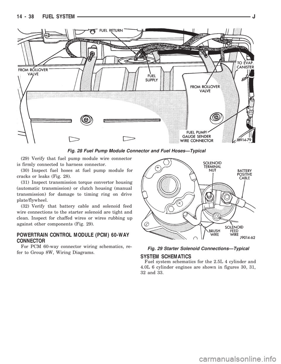
(29) Verify that fuel pump module wire connector
is firmly connected to harness connector.
(30) Inspect fuel hoses at fuel pump module for
cracks or leaks (Fig. 28).
(31) Inspect transmission torque convertor housing
(automatic transmission) or clutch housing (manual
transmission) for damage to timing ring on drive
plate/flywheel.
(32) Verify that battery cable and solenoid feed
wire connections to the starter solenoid are tight and
clean. Inspect for chaffed wires or wires rubbing up
against other components (Fig. 29).
POWERTRAIN CONTROL MODULE (PCM) 60-WAY
CONNECTOR
For PCM 60-way connector wiring schematics, re-
fer to Group 8W, Wiring Diagrams.
SYSTEM SCHEMATICS
Fuel system schematics for the 2.5L 4 cylinder and
4.0L 6 cylinder engines are shown in figures 30, 31,
32 and 33.
Fig. 28 Fuel Pump Module Connector and Fuel HosesÐTypical
Fig. 29 Starter Solenoid ConnectionsÐTypical
14 - 38 FUEL SYSTEMJ
Page 129 of 1784
harness connector terminal-2 and the sensor connec-
tor terminal. Also test terminal-4 to the sensor con-
nector terminal. Repair the wire harness as
necessary if the resistance is greater than 1 ohm.
FUEL PUMP RELAY TESTING
For testing this relay, refer to RelaysÐOperation/
Testing in this section of the group.
MANIFOLD ABSOLUTE PRESSURE (MAP) SENSOR
TEST
To perform a complete test of the MAP sensor and
its circuitry, refer to DRB scan tool and appropriate
Powertrain Diagnostics Procedures manual. To test
the sensor only, refer to the following:
Inspect the MAP sensor vacuum hose connections
at the throttle body and sensor. Repair as necessary.
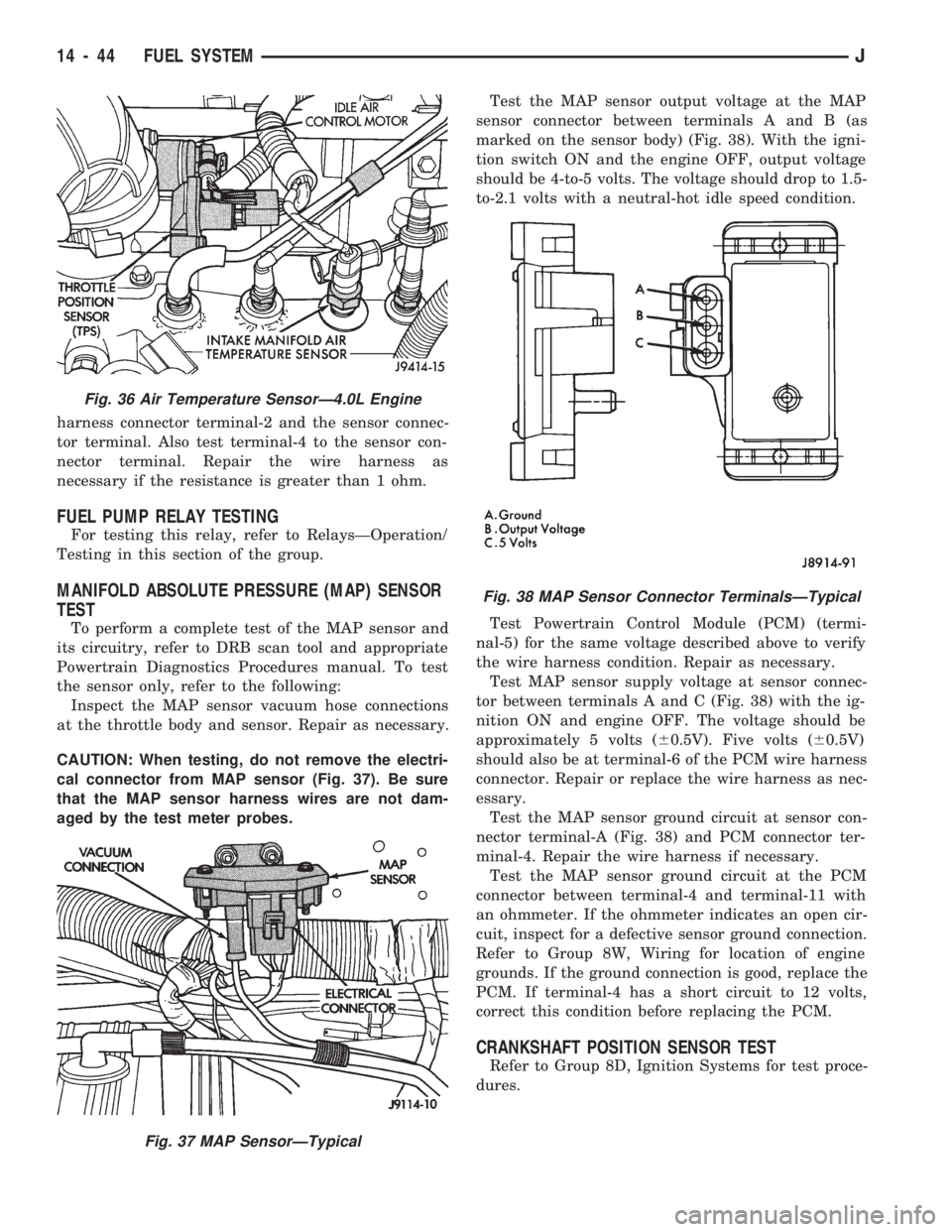
CAUTION: When testing, do not remove the electri-
cal connector from MAP sensor (Fig. 37). Be sure
that the MAP sensor harness wires are not dam-
aged by the test meter probes.Test the MAP sensor output voltage at the MAP
sensor connector between terminals A and B (as
marked on the sensor body) (Fig. 38). With the igni-
tion switch ON and the engine OFF, output voltage
should be 4-to-5 volts. The voltage should drop to 1.5-
to-2.1 volts with a neutral-hot idle speed condition.
Test Powertrain Control Module (PCM) (termi-
nal-5) for the same voltage described above to verify
the wire harness condition. Repair as necessary.
Test MAP sensor supply voltage at sensor connec-
tor between terminals A and C (Fig. 38) with the ig-
nition ON and engine OFF. The voltage should be
approximately 5 volts (60.5V). Five volts (60.5V)
should also be at terminal-6 of the PCM wire harness
connector. Repair or replace the wire harness as nec-
essary.
Test the MAP sensor ground circuit at sensor con-
nector terminal-A (Fig. 38) and PCM connector ter-
minal-4. Repair the wire harness if necessary.
Test the MAP sensor ground circuit at the PCM
connector between terminal-4 and terminal-11 with
an ohmmeter. If the ohmmeter indicates an open cir-
cuit, inspect for a defective sensor ground connection.
Refer to Group 8W, Wiring for location of engine
grounds. If the ground connection is good, replace the
PCM. If terminal-4 has a short circuit to 12 volts,
correct this condition before replacing the PCM.
CRANKSHAFT POSITION SENSOR TEST
Refer to Group 8D, Ignition Systems for test proce-
dures.
Fig. 36 Air Temperature SensorÐ4.0L Engine
Fig. 37 MAP SensorÐTypical
Fig. 38 MAP Sensor Connector TerminalsÐTypical
14 - 44 FUEL SYSTEMJ
Page 130 of 1784
EXTENDED IDLE SWITCH TEST
OPTIONAL POLICE PACKAGE ONLY
OPERATION
The extended idle switch is used to raise the en-
gine idle speed to approximately 1000 rpm when the
shifter is in either the Park or Neutral position. A
rocker-type 2-wire switch (extended idle switch) is
mounted to the instrument panel.This switch is
available only with 4.0L engine when supplied
with the optional police package.
TESTING
The extended idle switch will control a ground cir-
cuit going to the powertrain control module (PCM).
When a ground signal (through this switch) has been
received at pin number 10 in the PCM, engine idle
speed will increase.
Bring the engine to normal operating temperature
and turn the extended idle switch to the ON position.
Engine speed should now increase to approximately
1000 rpm when the shifter is in either the Park or
Neutral position. If engine speed does not increase,
apply a good ground to pin number 10 at the PCM
using a small paper clip. Be careful not to damage
the wiring with the paper clip. If the engine speed
now increases, it can be assumed that the PCM is
functioning correctly. Check the instrument panel
mounted switch for a closed ground circuit when in
the ON position. If the engine speed will not increase
after applying a ground to pin number 10, replace
the PCM. Refer to Group 8W, Wiring Diagrams for
circuit and wiring information.
THROTTLE POSITION SENSOR (TPS) TEST
To perform a complete test of the sensor and its cir-
cuitry, refer to DRB scan tool and appropriate Pow-
ertrain Diagnostics Procedures manual. To test the
sensor only, refer to the following:
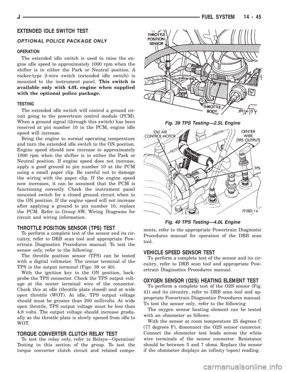
The throttle position sensor (TPS) can be tested
with a digital voltmeter. The center terminal of the
TPS is the output terminal (Figs. 39 or 40).
With the ignition key in the ON position, back-
probe the TPS connector. Check the TPS output volt-
age at the center terminal wire of the connector.
Check this at idle (throttle plate closed) and at wide
open throttle (WOT). At idle, TPS output voltage
should must be greater than 200 millivolts. At wide
open throttle, TPS output voltage must be less than
4.8 volts. The output voltage should increase gradu-
ally as the throttle plate is slowly opened from idle to
WOT.
TORQUE CONVERTER CLUTCH RELAY TEST
To test the relay only, refer to RelaysÐOperation/
Testing in this section of the group. To test the
torque converter clutch circuit and related compo-nents, refer to the appropriate Powertrain Diagnostic
Procedures manual for operation of the DRB scan
tool.
VEHICLE SPEED SENSOR TEST
To perform a complete test of the sensor and its cir-
cuitry, refer to DRB scan tool and appropriate Pow-
ertrain Diagnostics Procedures manual.
OXYGEN SENSOR (O2S) HEATING ELEMENT TEST
To perform a complete test of the O2S sensor (Fig.
41) and its circuitry, refer to DRB scan tool and ap-
propriate Powertrain Diagnostics Procedures manual.
To test the sensor only, refer to the following:
The oxygen sensor heating element can be tested
with an ohmmeter as follows:
With the sensor at room temperature 25 degrees C
(77 degrees F), disconnect the O2S sensor connector.
Connect the ohmmeter test leads across the white
wire terminals of the sensor connector. Resistance
should be between 5 and 7 ohms. Replace the sensor
if the ohmmeter displays an infinity (open) reading.
Fig. 39 TPS TestingÐ2.5L Engine
Fig. 40 TPS TestingÐ4.0L Engine
JFUEL SYSTEM 14 - 45
Page 150 of 1784
ABS BRAKE DIAGNOSIS
INDEX
page page
ABS Fault Diagnosis....................... 4
ABS System Wiring and Electrical Circuits...... 4
ABS Warning Light Display.................. 3
Brake Warning Light Display................. 4
Diagnosis Procedures...................... 3
ECU Diagnosis........................... 4
HCU Diagnosis........................... 4Loss of Sensor Input....................... 3
Operating Sound Levels.................... 3
Rear Speed Sensor Air Gap................. 3
Steering Response........................ 3
Vehicle Response in Antilock Mode............ 3
Wheel/Tire Size and Input Signals............. 3
DIAGNOSIS PROCEDURES
ABS diagnosis involves three basic steps. First is
observation of the warning light display. Second is a
visual examination for low fluid level, leaks, parking
brakes applied, or obvious damage to system compo-
nents or wires. The third step involves using the
DRB II scan tool to identify a faulty component.
The visual examination requires a check of reser-
voir fluid level and all system components. Things to
look for are leaks, loose connections, or obvious com-
ponent damage.
The final diagnosis step involves using the DRB II
scan tool to determine the specific circuit or compo-
nent at fault. The tester is connected to the ABS di-
agnostic connector in the passenger compartment.
The connector is at the driver side of the center con-
sole under the instrument panel. Refer to the DRB II
scan tool Manual for tester procedures. Also refer to
the ABS Fault Diagnosis charts at the end of this
section for additional diagnosis information.
Initial faults should be cleared and the vehicle road
tested to reset any faults that remain in the system.
Faults can be cleared with the DRB II scan tool.
REAR SPEED SENSOR AIR GAP
The front wheel sensors are fixed and cannot be ad-
justed. Only the rear sensor air gap is adjustable. Air
gap must be set with a brass feeler gauge.
Correct air gap is important to proper signal gen-
eration. An air gap that is too large may cause com-
plete loss of sensor input. Or, a gap that is too small
could produce a false input signal, or damaging con-
tact between the sensor and tone ring.
WHEEL/TIRE SIZE AND INPUT SIGNALS
Antilock system operation is dependant on accurate
signals from the wheel speed sensors. Ideally, the ve-
hicle wheels and tires should all be the same size
and type. However, the Jeep ABS system is designed
to function with a compact spare tire installed.
OPERATING SOUND LEVELS
The ABS pump and solenoid valves may produce
some sound as they cycle on and off. This is a normal
condition and should not be mistaken for faulty oper-
ation.
VEHICLE RESPONSE IN ANTILOCK MODE
During antilock braking, the HCU solenoid valves
cycle rapidly in response to ECU inputs.
The driver will experience a pulsing sensation
within the vehicle as the solenoids decrease, hold, or
increase pressure as needed. A pulsing brake pedal
will also be noted.
The pulsing sensation occurs as the solenoids cycle
during antilock mode braking. A slight pulse in the
brake pedal may also be noted during the dynamic
self check part of system initialization.
STEERING RESPONSE
A modest amount of steering input is required dur-
ing extremely high deceleration braking, or when
braking on differing traction surfaces. An example of
differing traction surfaces would be when the left
side wheels are on ice and the right side wheels are
on dry pavement.
LOSS OF SENSOR INPUT
Sensor malfunctions will most likely be due to
loose connections, damaged sensor wires, incorrect
rear sensor air gap, or a malfunctioning sensor. Ad-
ditional causes of sensor faults would be sensor and
tone ring misalignment or damage.
ABS WARNING LIGHT DISPLAY
ABS Light Illuminates At Startup
The amber ABS light illuminates at startup as
part of the system self check feature. The light illu-
minates for 2-3 seconds then goes off as part of the
normal self check routine.
ABS Light Remains On After Startup
An ABS system fault is indicated when the light
remains on after startup. Diagnosis with the DRB II
JBRAKES 5 - 3