1994 JEEP CHEROKEE wiring
[x] Cancel search: wiringPage 289 of 1784
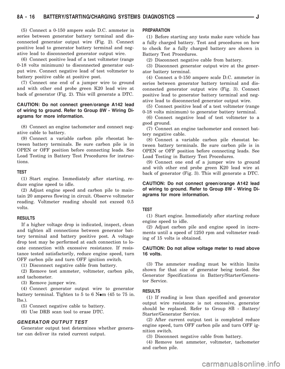
(5) Connect a 0-150 ampere scale D.C. ammeter in
series between generator battery terminal and dis-
connected generator output wire (Fig. 2). Connect
positive lead to generator battery terminal and neg-
ative lead to disconnected generator output wire.
(6) Connect positive lead of a test voltmeter (range
0-18 volts minimum) to disconnected generator out-
put wire. Connect negative lead of test voltmeter to
battery positive cable at positive post.
(7) Connect one end of a jumper wire to ground
and with other end probe green K20 lead wire at
back of generator (Fig. 2). This will generate a DTC.
CAUTION: Do not connect green/orange A142 lead
of wiring to ground. Refer to Group 8W - Wiring Di-
agrams for more information.
(8) Connect an engine tachometer and connect neg-
ative cable to battery.
(9) Connect a variable carbon pile rheostat be-
tween battery terminals. Be sure carbon pile is in
OPEN or OFF position before connecting leads. See
Load Testing in Battery Test Procedures for instruc-
tions.
TEST
(1) Start engine. Immediately after starting, re-
duce engine speed to idle.
(2) Adjust engine speed and carbon pile to main-
tain 20 amperes flowing in circuit. Observe voltmeter
reading. Voltmeter reading should not exceed 0.5
volts.
RESULTS
If a higher voltage drop is indicated, inspect, clean
and tighten all connections between generator bat-
tery terminal and battery positive post. A voltage
drop test may be performed at each connection to lo-
cate connection with excessive resistance. If resis-
tance tested satisfactorily, reduce engine speed, turn
OFF carbon pile and turn OFF ignition switch.
(1) Disconnect negative cable from battery.
(2) Remove test ammeter, voltmeter, carbon pile,
and tachometer.
(3) Remove jumper wire.
(4) Connect generator output wire to generator
battery terminal. Tighten to 5 to 6 NIm (45 to 75 in.
lbs.).
(5) Connect negative cable to battery.
(6) Use DRB scan tool to erase DTC.
GENERATOR OUTPUT TEST
Generator output test determines whether genera-
tor can deliver its rated current output.PREPARATION
(1) Before starting any tests make sure vehicle has
a fully charged battery. Test and procedures on how
to check for a fully charged battery are shown in
Battery Test Procedures.
(2) Disconnect negative cable from battery.
(3) Disconnect generator output wire at the gener-
ator battery terminal.
(4) Connect a 0-150 ampere scale D.C. ammeter in
series between generator battery terminal and dis-
connected generator output wire (Fig. 3). Connect
positive lead to generator battery terminal and neg-
ative lead to disconnected generator output wire.
(5) Connect positive lead of a test voltmeter (range
0-18 volts minimum) to generator battery terminal.
(6) Connect negative lead of test voltmeter to a
good ground.
(7) Connect an engine tachometer and connect bat-
tery negative cable.
(8) Connect a variable carbon pile rheostat be-
tween battery terminals. Be sure carbon pile is in
OPEN or OFF position before connecting leads. See
Load Testing in Battery Test Procedures.
(9) Connect one end of a jumper wire to ground
and with other end probe green K20 lead wire at
back of generator (Fig. 3). This will generate a DTC.
CAUTION: Do not connect green/orange A142 lead
of wiring to ground. Refer to Group 8W - Wiring Di-
agrams for more information.
TEST
(1) Start engine. Immediately after starting reduce
engine speed to idle.
(2) Adjust carbon pile and engine speed in incre-
ments until a speed of 1250 rpm and voltmeter read-
ing of 15 volts is obtained.
CAUTION: Do not allow voltage meter to read above
16 volts.
(3) The ammeter reading must be within limits
shown for that size of generator being tested. See
Generator Specifications in Battery/Starter/Genera-
tor Service.
RESULTS
(1) If reading is less than specified and generator
output wire resistance is not excessive, generator
should be replaced. Refer to Group 8B - Battery/
Starter/Generator Service.
(2) After current output test is completed reduce
engine speed, turn OFF carbon pile and turn OFF ig-
nition switch.
(3) Disconnect negative cable from battery.
(4) Remove test ammeter, voltmeter, tachometer
and carbon pile.
8A - 16 BATTERY/STARTING/CHARGING SYSTEMS DIAGNOSTICSJ
Page 311 of 1784
(6) Should any segment in any of the digit positions
fail to light, the unit is defective and should be re-
placed.
THERMOMETER AND SENSOR SYSTEM REPAIR
PROCEDURES
This portion of the display consists of a sensor, the
circuit and display devoted to the temperature mea-
suring and display. The sensor is mounted at the
center of the vehicle below the grille, behind the
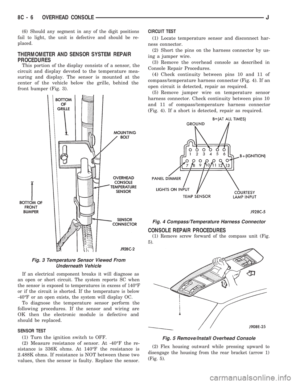
front bumper (Fig. 3).
If an electrical component breaks it will diagnose as
an open or short circuit. The system reports SC when
the sensor is exposed to temperatures in excess of 140ÉF
or if the circuit is shorted. If the temperature is below
-40ÉF or an open exists, the system will display OC.
To diagnose the temperature sensor perform the
following procedures. If the sensor and wiring are
OK then the electronic module is defective and
should be replaced.
SENSOR TEST
(1) Turn the ignition switch to OFF.
(2) Measure resistance of sensor. At -40ÉF the re-
sistance is 336K ohms. At 140ÉF the resistance is
2.488K ohms. If resistance is NOT between these two
values, then the sensor is faulty. Replace the sensor.CIRCUIT TEST
(1) Locate temperature sensor and disconnect har-
ness connector.
(2) Short the pins on the harness connector by us-
ing a jumper wire.
(3) Remove the overhead console as described in
Console Repair Procedures.
(4) Check continuity between pins 10 and 11 of
compass/temperature harness connector (Fig. 4). If an
open circuit is detected, repair as required.
(5) Remove jumper wire on temperature sensor
harness connector. Check continuity between pins 10
and 11 of compass/temperature harness connector
(Fig. 4). If a short is detected, repair as required.
CONSOLE REPAIR PROCEDURES
(1) Remove screw forward of the compass unit (Fig.
5).
(2) Flex housing outward while pressing upward to
disengage the housing from the rear bracket (arrow 1)
(Fig. 5).
Fig. 4 Compass/Temperature Harness Connector
Fig. 5 Remove/Install Overhead Console
Fig. 3 Temperature Sensor Viewed From
Underneath Vehicle
8C - 6 OVERHEAD CONSOLEJ
Page 321 of 1784

DIAGNOSTICS/SERVICE PROCEDURES
INDEX
page page
Automatic Shut Down (ASD) Relay............ 8
Camshaft Position Sensor Test............... 8
Crankshaft Position Sensor Test.............. 9
Distributor Cap........................... 9
Distributor Rotor......................... 10
DRB Scan Tool.......................... 10
Engine Coolant Temperature Sensor Test...... 12
General Information........................ 8
Ignition Coil............................. 11
Ignition Secondary Circuit Diagnosis.......... 12Ignition Timing........................... 14
Intake Manifold Air Temperature Sensor Test . . . 14
Manifold Absolute Pressure (MAP) Sensor Test . 14
On-Board Diagnostics (OBD)................ 19
Oxygen Sensor Tests..................... 19
Powertrain Control Module (PCM)............ 15
Spark Plug Secondary Cables............... 17
Spark Plugs............................ 16
Throttle Position Sensor Test............... 18
GENERAL INFORMATION
This section of the group, Diagnostics/Service Pro-
cedures, will discuss basic ignition system diagnos-
tics and service adjustments.
For system operation and component identification,
refer to the Component Identification/System Opera-
tion section of this group.
For removal or installation of ignition system com-
ponents, refer to the Component Removal/Installa-
tion section of this group.
For other useful information, refer to On-Board Di-
agnostics in the General Diagnosis sections of Group
14, Fuel System in this manual.
For operation of the DRB Scan Tool, refer to the
appropriate Powertrain Diagnostic Procedures ser-
vice manual.
AUTOMATIC SHUT DOWN (ASD) RELAY
Refer to RelaysÐOperation/Testing in the Group
14, Fuel System section of this service manual.
CAMSHAFT POSITION SENSOR TEST
The camshaft position sensor is located in the dis-
tributor on all engines.
To perform a complete test of this sensor and its
circuitry, refer to the DRB scan tool. Also refer to the
appropriate Powertrain Diagnostics Procedures man-
ual. To test the sensor only, refer to the following:
2.5L OR 4.0L ENGINE
For this test, an analog voltmeter is needed.Do
not remove the distributor connector from the dis-
tributor. Using small paper clips, insert them into
the backside of the distributor wire harness connec-
tor to make contact with the terminals. Be sure that
the connector is not damaged when inserting the pa-
per clips. Attach voltmeter leads to these paper clips.
(1) Connect the positive (+) voltmeter lead into
the sensor output wire. This is at done the distribu-
tor wire harness connector. For wire identification,
refer to Group 8W, Wiring Diagrams.(2) Connect the negative (-) voltmeter lead into the
ground wire. For wire identification, refer to Group
8W, Wiring Diagrams.
(3) Set the voltmeter to the 15 Volt DC scale.
(4) Remove distributor cap. Rotate (crank) engine
with starter until pulse ring (Fig. 1) enters the mag-
netic pickup on camshaft position sensor. Distributor
rotor should be pointed in 9 o'clock position. The
movable pulse ring should now be within the sensor
pickup.
(5) Turn ignition key to ON position. Voltmeter
should read approximately 5.0 volts.
(6) If voltage is not present, check the voltmeter
leads for a good connection.
(7) If voltage is still not present, check for voltage
at the supply wire. For wire identification, refer to
Group 8W, Wiring Diagrams.
Fig. 1 Pulse Ring/Rotor PositionÐTypical
8D - 8 IGNITION SYSTEMSJ
Page 322 of 1784
(8) If voltage is not present at supply wire, check
for voltage at pin 7 of Powertrain Control Module
(PCM) 60-way connector. Leave the PCM connector
connected for this test.
(9) If voltage is still not present, perform vehicle
test using the DRB scan tool.
(10) If voltage is present at pin 7, but not at the
supply wire:
(a) Check continuity between the supply wire.
This is checked between the distributor connector
and pin 7 at the PCM. If continuity is not present,
repair the harness as necessary.
(b) Check for continuity between the camshaft
position sensor output wire and pin 44 at the PCM.
If continuity is not present, repair the harness as
necessary.
(c) Check for continuity between the ground cir-
cuit wire at the distributor connector and ground.
If continuity is not present, repair the harness as
necessary.
(11) While observing the voltmeter, crank the en-
gine with ignition switch. The voltmeter needle
should fluctuate between 0 and 5 volts while the en-
gine is cranking. This verifies that the camshaft po-
sition sensor in the distributor is operating properly
and a sync pulse signal is being generated.
If sync pulse signal is not present, replacement of
the camshaft position sensor is necessary.
For removal or installation of ignition system com-
ponents, refer to the Component Removal/Installa-
tion section of this group.
For system operation and component identification,
refer to the Component Identification/System Opera-
tion section of this group.
CRANKSHAFT POSITION SENSOR TEST
To perform a complete test of this sensor and its
circuitry, refer to the DRB scan tool. Also refer to the
appropriate Powertrain Diagnostics Procedures man-
ual. To test the sensor only, refer to the following:
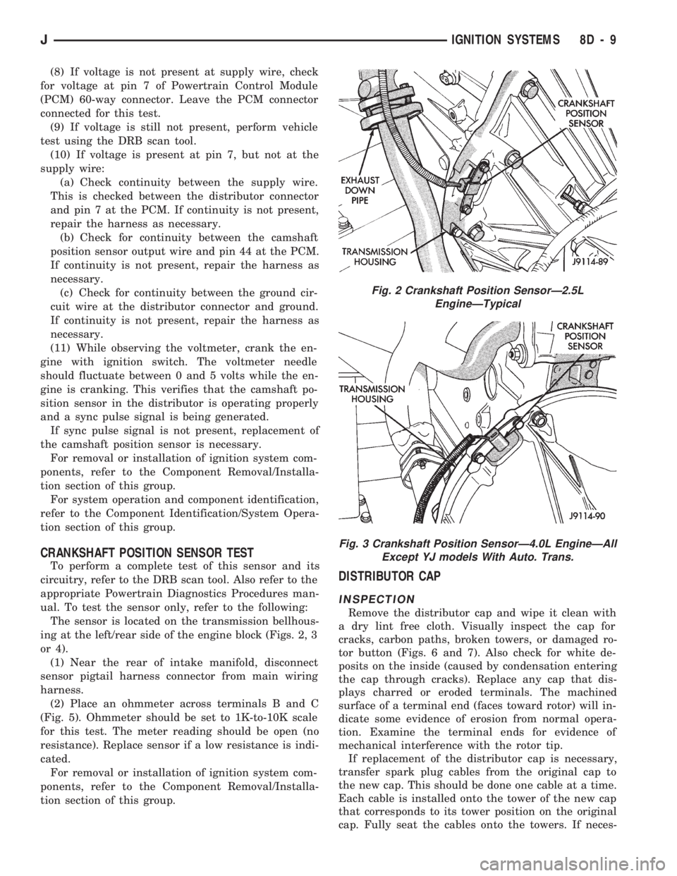
The sensor is located on the transmission bellhous-
ing at the left/rear side of the engine block (Figs. 2, 3
or 4).
(1) Near the rear of intake manifold, disconnect
sensor pigtail harness connector from main wiring
harness.
(2) Place an ohmmeter across terminals B and C
(Fig. 5). Ohmmeter should be set to 1K-to-10K scale
for this test. The meter reading should be open (no
resistance). Replace sensor if a low resistance is indi-
cated.
For removal or installation of ignition system com-
ponents, refer to the Component Removal/Installa-
tion section of this group.
DISTRIBUTOR CAP
INSPECTION
Remove the distributor cap and wipe it clean with
a dry lint free cloth. Visually inspect the cap for
cracks, carbon paths, broken towers, or damaged ro-
tor button (Figs. 6 and 7). Also check for white de-
posits on the inside (caused by condensation entering
the cap through cracks). Replace any cap that dis-
plays charred or eroded terminals. The machined
surface of a terminal end (faces toward rotor) will in-
dicate some evidence of erosion from normal opera-
tion. Examine the terminal ends for evidence of
mechanical interference with the rotor tip.
If replacement of the distributor cap is necessary,
transfer spark plug cables from the original cap to
the new cap. This should be done one cable at a time.
Each cable is installed onto the tower of the new cap
that corresponds to its tower position on the original
cap. Fully seat the cables onto the towers. If neces-
Fig. 2 Crankshaft Position SensorÐ2.5L
EngineÐTypical
Fig. 3 Crankshaft Position SensorÐ4.0L EngineÐAll
Except YJ models With Auto. Trans.
JIGNITION SYSTEMS 8D - 9
Page 326 of 1784
(4) Using insulated pliers, hold the cable terminal
approximately 12 mm (1/2 in.) from the engine cylin-
der head or block while rotating the engine with the
starter motor. Observe the spark plug cable terminal
for an arc. If steady arcing occurs, it can be expected
that the ignition secondary system is operating cor-
rectly. If steady arcing occurs at the spark plug ca-
bles, but the engine will not start, connect the DRB
scan tool. Refer to the Powertrain Diagnostic Proce-
dures service manual for DRB operation.
FAILURE TO START TEST
To prevent unnecessary diagnostic time and wrong
test results, the previous Checking For Spark test
should be performed prior to this test.
WARNING: SET PARKING BRAKE OR BLOCK THE
DRIVE WHEELS BEFORE PROCEEDING WITH THIS
TEST.
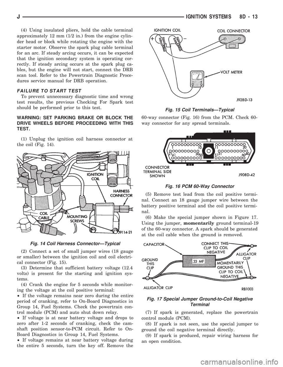
(1) Unplug the ignition coil harness connector at
the coil (Fig. 14).
(2) Connect a set of small jumper wires (18 gauge
or smaller) between the ignition coil and coil electri-
cal connector (Fig. 15).
(3) Determine that sufficient battery voltage (12.4
volts) is present for the starting and ignition sys-
tems.
(4) Crank the engine for 5 seconds while monitor-
ing the voltage at the coil positive terminal:
²If the voltage remains near zero during the entire
period of cranking, refer to On-Board Diagnostics in
Group 14, Fuel Systems. Check the powertrain con-
trol module (PCM) and auto shut down relay.
²If voltage is at near battery voltage and drops to
zero after 1-2 seconds of cranking, check the cam-
shaft position sensor-to-PCM circuit. Refer to On-
Board Diagnostics in Group 14, Fuel Systems.
²If voltage remains at near battery voltage during
the entire 5 seconds, turn the key off. Remove the60-way connector (Fig. 16) from the PCM. Check 60-
way connector for any spread terminals.
(5) Remove test lead from the coil positive termi-
nal. Connect an 18 gauge jumper wire between the
battery positive terminal and the coil positive termi-
nal.
(6) Make the special jumper shown in Figure 17.
Using the jumper,momentarilyground terminal-19
of the 60-way connector. A spark should be generated
at the coil cable when the ground is removed.
(7) If spark is generated, replace the powertrain
control module (PCM).
(8) If spark is not seen, use the special jumper to
ground the coil negative terminal directly.
(9) If spark is produced, repair wiring harness for
an open condition.
Fig. 14 Coil Harness ConnectorÐTypical
Fig. 15 Coil TerminalsÐTypical
Fig. 16 PCM 60-Way Connector
Fig. 17 Special Jumper Ground-to-Coil Negative
Terminal
JIGNITION SYSTEMS 8D - 13
Page 328 of 1784
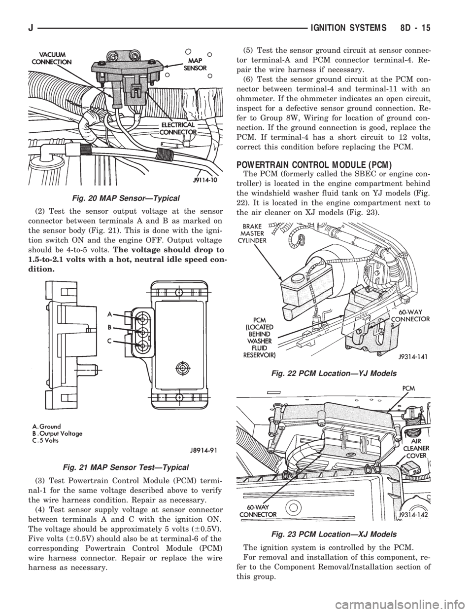
(2) Test the sensor output voltage at the sensor
connector between terminals A and B as marked on
the sensor body (Fig. 21). This is done with the igni-
tion switch ON and the engine OFF. Output voltage
should be 4-to-5 volts.The voltage should drop to
1.5-to-2.1 volts with a hot, neutral idle speed con-
dition.
(3) Test Powertrain Control Module (PCM) termi-
nal-1 for the same voltage described above to verify
the wire harness condition. Repair as necessary.
(4) Test sensor supply voltage at sensor connector
between terminals A and C with the ignition ON.
The voltage should be approximately 5 volts (60.5V).
Five volts (60.5V) should also be at terminal-6 of the
corresponding Powertrain Control Module (PCM)
wire harness connector. Repair or replace the wire
harness as necessary.(5) Test the sensor ground circuit at sensor connec-
tor terminal-A and PCM connector terminal-4. Re-
pair the wire harness if necessary.
(6) Test the sensor ground circuit at the PCM con-
nector between terminal-4 and terminal-11 with an
ohmmeter. If the ohmmeter indicates an open circuit,
inspect for a defective sensor ground connection. Re-
fer to Group 8W, Wiring for location of ground con-
nection. If the ground connection is good, replace the
PCM. If terminal-4 has a short circuit to 12 volts,
correct this condition before replacing the PCM.
POWERTRAIN CONTROL MODULE (PCM)
The PCM (formerly called the SBEC or engine con-
troller) is located in the engine compartment behind
the windshield washer fluid tank on YJ models (Fig.
22). It is located in the engine compartment next to
the air cleaner on XJ models (Fig. 23).
The ignition system is controlled by the PCM.
For removal and installation of this component, re-
fer to the Component Removal/Installation section of
this group.
Fig. 20 MAP SensorÐTypical
Fig. 21 MAP Sensor TestÐTypical
Fig. 22 PCM LocationÐYJ Models
Fig. 23 PCM LocationÐXJ Models
JIGNITION SYSTEMS 8D - 15
Page 336 of 1784
INSTALLATION
(1) Install coolant temperature sensor into the
thermostat housing. Tighten to 28 Nzm (21 ft. lbs.)
torque.
(2) Connect the wire connector.
(3) Fill the cooling system. Refer to group 7, Cool-
ing System.
DISTRIBUTOR
All distributors contain an internal oil seal that
prevents oil from entering the distributor housing.
The seal is not serviceable.
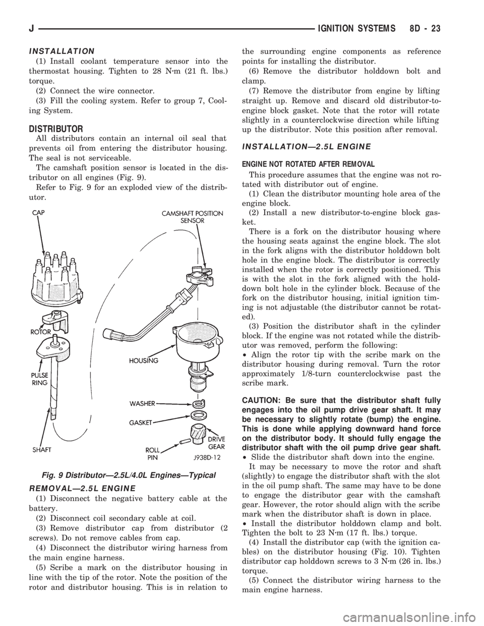
The camshaft position sensor is located in the dis-
tributor on all engines (Fig. 9).
Refer to Fig. 9 for an exploded view of the distrib-
utor.
REMOVALÐ2.5L ENGINE
(1) Disconnect the negative battery cable at the
battery.
(2) Disconnect coil secondary cable at coil.
(3) Remove distributor cap from distributor (2
screws). Do not remove cables from cap.
(4) Disconnect the distributor wiring harness from
the main engine harness.
(5) Scribe a mark on the distributor housing in
line with the tip of the rotor. Note the position of the
rotor and distributor housing. This is in relation tothe surrounding engine components as reference
points for installing the distributor.
(6) Remove the distributor holddown bolt and
clamp.
(7) Remove the distributor from engine by lifting
straight up. Remove and discard old distributor-to-
engine block gasket. Note that the rotor will rotate
slightly in a counterclockwise direction while lifting
up the distributor. Note this position after removal.
INSTALLATIONÐ2.5L ENGINE
ENGINE NOT ROTATED AFTER REMOVAL
This procedure assumes that the engine was not ro-
tated with distributor out of engine.
(1) Clean the distributor mounting hole area of the
engine block.
(2) Install a new distributor-to-engine block gas-
ket.
There is a fork on the distributor housing where
the housing seats against the engine block. The slot
in the fork aligns with the distributor holddown bolt
hole in the engine block. The distributor is correctly
installed when the rotor is correctly positioned. This
is with the slot in the fork aligned with the hold-
down bolt hole in the cylinder block. Because of the
fork on the distributor housing, initial ignition tim-
ing is not adjustable (the distributor cannot be rotat-
ed).
(3) Position the distributor shaft in the cylinder
block. If the engine was not rotated while the distrib-
utor was removed, perform the following:
²Align the rotor tip with the scribe mark on the
distributor housing during removal. Turn the rotor
approximately 1/8-turn counterclockwise past the
scribe mark.
CAUTION: Be sure that the distributor shaft fully
engages into the oil pump drive gear shaft. It may
be necessary to slightly rotate (bump) the engine.
This is done while applying downward hand force
on the distributor body. It should fully engage the
distributor shaft with the oil pump drive gear shaft.
²Slide the distributor shaft down into the engine.
It may be necessary to move the rotor and shaft
(slightly) to engage the distributor shaft with the slot
in the oil pump shaft. The same may have to be done
to engage the distributor gear with the camshaft
gear. However, the rotor should align with the scribe
mark when the distributor shaft is down in place.
²Install the distributor holddown clamp and bolt.
Tighten the bolt to 23 Nzm (17 ft. lbs.) torque.
(4) Install the distributor cap (with the ignition ca-
bles) on the distributor housing (Fig. 10). Tighten
distributor cap holddown screws to 3 Nzm (26 in. lbs.)
torque.
(5) Connect the distributor wiring harness to the
main engine harness.
Fig. 9 DistributorÐ2.5L/4.0L EnginesÐTypical
JIGNITION SYSTEMS 8D - 23
Page 337 of 1784
CAUTION: Do not puncture the spark plug cables or
boots to make the connection. Use proper adapters.
(6) Connect battery cable to battery.
ENGINE ROTATED AFTER REMOVAL
There is a fork on the distributor housing where
the housing seats against the engine block. The slot
in the fork aligns with the hole for the distributor
holddown bolt in the engine block. The distributor is
correctly installed when the rotor is correctly posi-
tioned. This is when the slot in the fork is aligned
with the hole for the distributor holddown bolt in the
cylinder block. Because of the fork on the distributor
housing, initial ignition timing is not adjustable (the
distributor cannot be rotated).
(1) If the engine was rotated while the distributor
was removed, it will be necessary to establish timing
according to following procedure:
²Remove the No. 1 spark plug. Hold a finger over
the spark plug hole and rotate the engine until com-
pression pressure is felt. Slowly continue to rotate
the engine. Do this until the timing index on vibra-
tion damper pulley aligns with top dead center (TDC)mark (0 degree) on timing degree scale. Always ro-
tate the engine in direction of normal rotation. Do
not turn the engine backward to align the timing
marks.
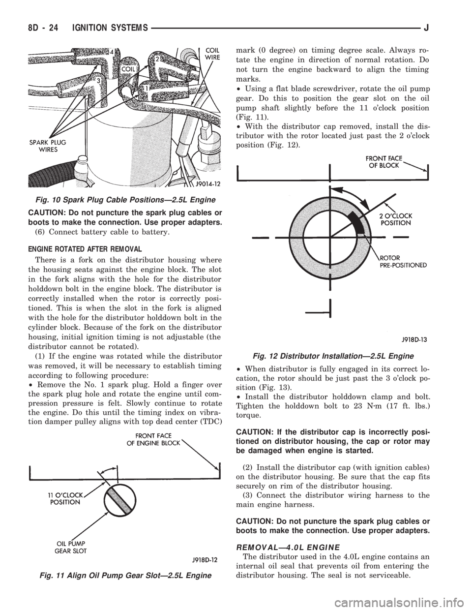
²Using a flat blade screwdriver, rotate the oil pump
gear. Do this to position the gear slot on the oil
pump shaft slightly before the 11 o'clock position
(Fig. 11).
²With the distributor cap removed, install the dis-
tributor with the rotor located just past the 2 o'clock
position (Fig. 12).
²When distributor is fully engaged in its correct lo-
cation, the rotor should be just past the 3 o'clock po-
sition (Fig. 13).
²Install the distributor holddown clamp and bolt.
Tighten the holddown bolt to 23 Nzm (17 ft. lbs.)
torque.
CAUTION: If the distributor cap is incorrectly posi-
tioned on distributor housing, the cap or rotor may
be damaged when engine is started.
(2) Install the distributor cap (with ignition cables)
on the distributor housing. Be sure that the cap fits
securely on rim of the distributor housing.
(3) Connect the distributor wiring harness to the
main engine harness.
CAUTION: Do not puncture the spark plug cables or
boots to make the connection. Use proper adapters.
REMOVALÐ4.0L ENGINE
The distributor used in the 4.0L engine contains an
internal oil seal that prevents oil from entering the
distributor housing. The seal is not serviceable.
Fig. 11 Align Oil Pump Gear SlotÐ2.5L Engine
Fig. 10 Spark Plug Cable PositionsÐ2.5L Engine
Fig. 12 Distributor InstallationÐ2.5L Engine
8D - 24 IGNITION SYSTEMSJ