1994 JEEP CHEROKEE water pump
[x] Cancel search: water pumpPage 4 of 1784
Above that temperature range the viscosity will de-
crease, and below that range the viscosity will in-
crease.
An engine oil with an SAE 5W-30 viscosity grade
provides good flow capability for fast cold weather
engine starts. The viscosity will then increase with
engine temperature to provide good high-tempera-
ture engine lubrication.
API SERVICE GRADE
The API Service Grade specifies the type of engine/
operating conditions for which the oil is intended.
The API Service Grade specifications also apply to
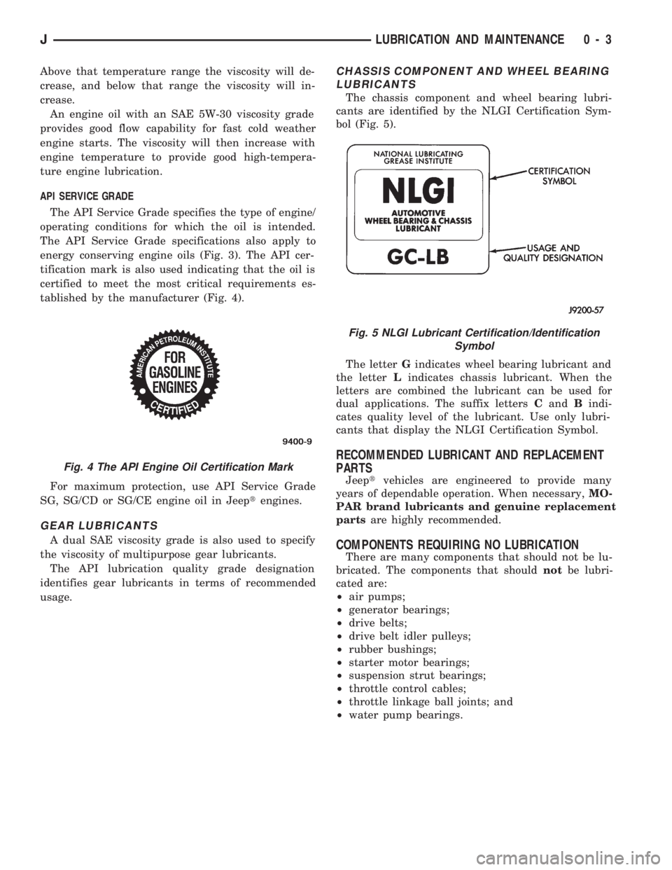
energy conserving engine oils (Fig. 3). The API cer-
tification mark is also used indicating that the oil is
certified to meet the most critical requirements es-
tablished by the manufacturer (Fig. 4).
For maximum protection, use API Service Grade
SG, SG/CD or SG/CE engine oil in Jeeptengines.
GEAR LUBRICANTS
A dual SAE viscosity grade is also used to specify
the viscosity of multipurpose gear lubricants.
The API lubrication quality grade designation
identifies gear lubricants in terms of recommended
usage.
CHASSIS COMPONENT AND WHEEL BEARING
LUBRICANTS
The chassis component and wheel bearing lubri-
cants are identified by the NLGI Certification Sym-
bol (Fig. 5).
The letterGindicates wheel bearing lubricant and
the letterLindicates chassis lubricant. When the
letters are combined the lubricant can be used for
dual applications. The suffix lettersCandBindi-
cates quality level of the lubricant. Use only lubri-
cants that display the NLGI Certification Symbol.
RECOMMENDED LUBRICANT AND REPLACEMENT
PARTS
Jeeptvehicles are engineered to provide many
years of dependable operation. When necessary,MO-
PAR brand lubricants and genuine replacement
partsare highly recommended.
COMPONENTS REQUIRING NO LUBRICATION
There are many components that should not be lu-
bricated. The components that shouldnotbe lubri-
cated are:
²air pumps;
²generator bearings;
²drive belts;
²drive belt idler pulleys;
²rubber bushings;
²starter motor bearings;
²suspension strut bearings;
²throttle control cables;
²throttle linkage ball joints; and
²water pump bearings.
Fig. 4 The API Engine Oil Certification Mark
Fig. 5 NLGI Lubricant Certification/Identification
Symbol
JLUBRICATION AND MAINTENANCE 0 - 3
Page 93 of 1784
pressure is bleeding past the (in-tank mounted) fuel
pump outlet check valve. Replace Fuel Pump Module
assembly. Refer to Fuel Pump Module removal and
installation in this group. If pressure drop is within
specifications, proceed to next step.
(13) Clamp off the rubber hose portion of adapter
tool number 6631 connected to the fuel supply line.
Allow engine to set for 30 minutes. If pressure has
dropped more than 138 kPa (20 psi) in 30 minutes,
pressure is bleeding past the fuel pressure regulator.
Replace fuel pressure regulator. Refer to Fuel Rail
removal and installation in the Component Removal/
Installation section of this group.
MECHANICAL MALFUNCTIONS
Mechanical malfunctions are more difficult to diag-
nose with this system. The powertrain control mod-
ule (PCM) has been programmed to compensate for
some mechanical malfunctions such as incorrect cam
timing, vacuum leaks, etc. If engine performance
problems are encountered and diagnostic trouble
codes are not displayed, the problem may be mechan-
ical rather than electronic.
FUEL FILTER
The fuel filter protects the fuel injectors and fuel
pressure regulator from dirt, water and other foreign
matter. The filter is located under the vehicle along
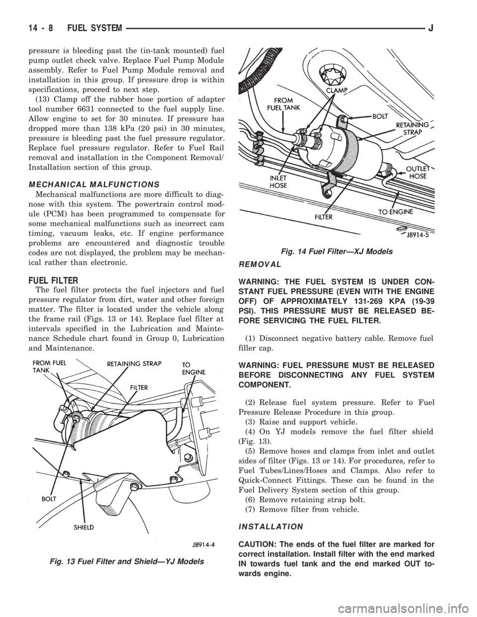
the frame rail (Figs. 13 or 14). Replace fuel filter at
intervals specified in the Lubrication and Mainte-
nance Schedule chart found in Group 0, Lubrication
and Maintenance.
REMOVAL
WARNING: THE FUEL SYSTEM IS UNDER CON-
STANT FUEL PRESSURE (EVEN WITH THE ENGINE
OFF) OF APPROXIMATELY 131-269 KPA (19-39
PSI). THIS PRESSURE MUST BE RELEASED BE-
FORE SERVICING THE FUEL FILTER.
(1) Disconnect negative battery cable. Remove fuel
filler cap.
WARNING: FUEL PRESSURE MUST BE RELEASED
BEFORE DISCONNECTING ANY FUEL SYSTEM
COMPONENT.
(2) Release fuel system pressure. Refer to Fuel
Pressure Release Procedure in this group.
(3) Raise and support vehicle.
(4) On YJ models remove the fuel filter shield
(Fig. 13).
(5) Remove hoses and clamps from inlet and outlet
sides of filter (Figs. 13 or 14). For procedures, refer to
Fuel Tubes/Lines/Hoses and Clamps. Also refer to
Quick-Connect Fittings. These can be found in the
Fuel Delivery System section of this group.
(6) Remove retaining strap bolt.
(7) Remove filter from vehicle.
INSTALLATION
CAUTION: The ends of the fuel filter are marked for
correct installation. Install filter with the end marked
IN towards fuel tank and the end marked OUT to-
wards engine.
Fig. 13 Fuel Filter and ShieldÐYJ Models
Fig. 14 Fuel FilterÐXJ Models
14 - 8 FUEL SYSTEMJ
Page 155 of 1784
(2) If red warning light is illuminated, or if neither
warning light is illuminated, make several stops and
note pedal action and brake response.
(3) Check brake pedal response with transmission
in Neutral and engine running. Pedal should remain
firm under steady foot pressure. If pedal falls away,
problem is either in vacuum booster or master cylin-
der.
(4) During road test, make normal and firm brake
stops in 25-40 mph range. Note faulty brake opera-
tion such as pull, grab, drag, noise, fade, pedal pul-
sation, etc.
(5) Inspect suspect brake components and refer to
problem diagnosis information for causes of various
brake conditions.
COMPONENT INSPECTION
Fluid leak points and dragging brake units can
usually be located without removing any compo-
nents. The area around a leak point will be wet with
fluid. The components at a dragging brake unit
(wheel, tire, rotor) will be quite warm or hot to the
touch.
Other brake problem conditions will require compo-
nent removal for proper inspection. Raise the vehicle
and remove the necessary wheels for better visual ac-
cess.
During component inspection, pay particular atten-
tion to heavily rusted/corroded brake components
(e.g. rotors, caliper pistons, brake return/holddown
springs, support plates, etc.).
Heavy accumulations of rust may be covering se-
vere damage to a brake component. It is wise to re-
move surface rust in order to accurately determine
the depth of rust penetration and damage. Light sur-
face rust is fairly normal and not a major concern (as
long as it is removed). However, heavy rust buildup,
especially on high mileage vehicles may cover struc-
tural damage to such important components as
brakelines, rotors, support plates, and brake boosters.
Refer to the wheel brake service procedures in this
group for more information.
DIAGNOSING SERVICE BRAKE PROBLEMS
BRAKE WARNING LIGHT OPERATION
The red brake warning light will illuminate under
the following conditions:
²for 2-3 seconds at startup as part of normal bulb
check
²parking brakes applied
²low pedal caused by malfunction in front/rear
brake hydraulic circuit (differential switch valve ac-
tuated)
If the red light remains on after startup, first ver-
ify that the parking brakes are fully released. Then
check pedal action and fluid level. A red light indi-
cates that the valve in the differential pressureswitch has been actuated. If a problem is confirmed,
inspect the hydraulic system and wheel brake compo-
nents.
On models with ABS brakes, the amber warning
light only illuminates when an ABS component has
malfunctioned. The ABS light operates indepen-
dently of the red warning light. Refer to the antilock
brake section for more detailed diagnosis informa-
tion.
PEDAL FALLS AWAY
A brake pedal that falls away under steady foot
pressure is generally the result of a system leak. The
leak point could be at a brakeline, fitting, hose,
wheel cylinder, or caliper. Internal leakage in the
master cylinder caused by worn or damaged piston
cups, may also be the problem cause.
If leakage is severe, fluid will be evident at or
around the leaking component. However internal
leakage in the master cylinder will not be physically
evident. Refer to the cylinder test procedure in this
section.
LOW PEDAL
If a low pedal is experienced, pump the pedal sev-
eral times. If the pedal comes back up, worn lining
and worn rotors or drums are the most likely causes.
However, if the pedal remains low and/or the warn-
ing light illuminates, the problem is in the master
cylinder, wheel cylinders, or calipers.
A decrease in master cylinder fluid level may only
be the result of normal lining wear. Fluid level will
decrease as lining wear occurs. It is a result of the
outward movement of caliper and wheel cylinder pis-
tons to compensate for normal wear.
SPONGY PEDAL
A spongy pedal is most often caused by air in the
system. However, thin drums or substandard brake
lines and hoses will also cause a condition similar to
a spongy pedal. The proper course of action is to
bleed the system, or replace thin drums and suspect
quality brake lines and hoses.
HARD PEDAL OR HIGH PEDAL EFFORT
A hard pedal or high pedal effort may be due to
lining that is water soaked, contaminated, glazed, or
badly worn. The power booster or check valve could
also be faulty. Test the booster and valve as de-
scribed in this section.
BRAKE DRAG
Brake drag occurs when the lining is in constant
contact with the rotor or drum. Drag can occur at
one wheel, all wheels, fronts only, or rears only. It is
a product of incomplete brakeshoe release. Drag can
be minor or severe enough to overheat the linings,
rotors and drums.
5 - 8 BRAKESJ
Page 234 of 1784
COOLING SYSTEM
CONTENTS
page page
DIAGNOSIS............................. 4
ENGINE ACCESSORY DRIVE BELTS........ 31
ENGINE BLOCK HEATER................. 37GENERAL INFORMATION.................. 1
SERVICE PROCEDURES................... 9
SPECIFICATIONS....................... 38
GENERAL INFORMATION
Throughout this group, references are made to par-
ticular vehicle models by alphabetical designation
(XJ or YJ) or by the particular vehicle nameplate. A
chart showing a breakdown of alphabetical designa-
tions is included in the Introduction section at the
beginning of this manual.
COOLING SYSTEM
The cooling system regulates engine operating tem-
perature. It allows the engine to reach normal oper-
ating temperature as quickly as possible, maintains
normal operating temperature and prevents over-
heating.
The cooling system also provides a means of heat-
ing the passenger compartment and cooling the auto-
matic transmission fluid (if equipped). The cooling
system is pressurized and uses a centrifugal water
pump to circulate coolant throughout the system.
An optional factory installed heavy duty cooling
package is available on most models. The package
consists of a radiator that has an increased numberof cooling fins. XJ models equipped with a 4.0L 6 cyl-
inder engine and heavy duty cooling and/or air con-
ditioning also have an auxiliary electric cooling fan.
COOLING SYSTEM COMPONENTS
The cooling system consists of:
²A radiator
²Cooling fan (mechanical and/or electrical)
²Thermal viscous fan drive
²Fan shroud
²Radiator pressure cap
²Thermostat
²Coolant reserve/overflow system
²Transmission oil cooler (if equipped with an auto-
matic transmission)
²Coolant
²Water pump
²Hoses and hose clamps
SYSTEM COOLANT ROUTING
For cooling system flow routings, refer to Figs. 1, 2,
3or4.
JCOOLING SYSTEM 7 - 1
Page 238 of 1784
ERASING TROUBLE CODES
After the problem has been repaired, the DRB scan
tool must be used to erase a DTC. Refer to the ap-
propriate Powertrain Diagnostic Procedures service
manual for operation of the DRB scan tool.
DRB SCAN TOOL
For operation of the DRB scan tool, refer to the ap-
propriate Powertrain Diagnostic Procedures service
manual.
PRELIMINARY CHECKS
ENGINE COOLING SYSTEM OVERHEATING
Establish what driving conditions caused the com-
plaint. Abnormal loads on the cooling system such as
the following may be the cause.
1. PROLONGED IDLE, VERY HIGH AMBI-
ENT TEMPERATURE, SLIGHT TAIL WIND AT
IDLE, SLOW TRAFFIC, TRAFFIC JAMS, HIGH
SPEED, OR STEEP GRADES:
Driving techniques that avoid overheating are:
²Idle with A/C off when temperature gauge is at
end of normal range.
²Increasing engine speed for more air flow is recom-
mended.2. TRAILER TOWING:
Consult Trailer Towing section of owners manual.
Do not exceed limits.
3. AIR CONDITIONING; ADD-ON OR AFTER
MARKET:
A maximum cooling package should have been or-
dered with vehicle if add-on or after market A/C is
installed. If not, maximum cooling system compo-
nents should be installed for model involved per
manufacturer's specifications.
4. RECENT SERVICE OR ACCIDENT RE-
PAIR:
Determine if any recent service has been performed
on vehicle that may effect cooling system. This may
be:
²Engine adjustments (incorrect timing)
²Slipping engine accessory drive belt(s)
²Brakes (possibly dragging)
²Changed parts (incorrect water pump rotating in
wrong direction)
²Reconditioned radiator or cooling system refilling
(possibly under-filled or air trapped in system).
If investigation reveals none of the above as a
cause for engine overheating complaint, refer to fol-
lowing Symptom and Action chart.
JCOOLING SYSTEM 7 - 5
Page 242 of 1784
SERVICE PROCEDURES
INDEX
page page
Coolant................................ 15
Coolant Reserve/Overflow System............ 19
Cooling System Cleaning/Reverse Flushing..... 17
Cooling System Fans..................... 26
Cooling System Hoses.................... 26
Draining Cooling System................... 16
Radiator Pressure Cap.................... 20
Radiators............................... 22Refilling Cooling System................... 17
Testing Cooling System for Leaks............ 18
Thermostat............................. 13
Transmission Oil Coolers................... 29
Water Pump Tests........................ 9
Water PumpsÐGeneral Information............ 9
Water PumpsÐRemoval/Installation........... 10
WATER PUMPSÐGENERAL INFORMATION
A centrifugal water pump circulates coolant
through the water jackets, passages, intake manifold,
radiator core, cooling system hoses and heater core.
The pump is driven from the engine crankshaft by a
drive belt on all engines.
The water pump impeller is pressed onto the rear
of a shaft that rotates in bearings pressed into the
housing. The housing has a small hole to allow seep-
age to escape. The water pump seals are lubricated
by the antifreeze in the coolant mixture. No addi-
tional lubrication is necessary.
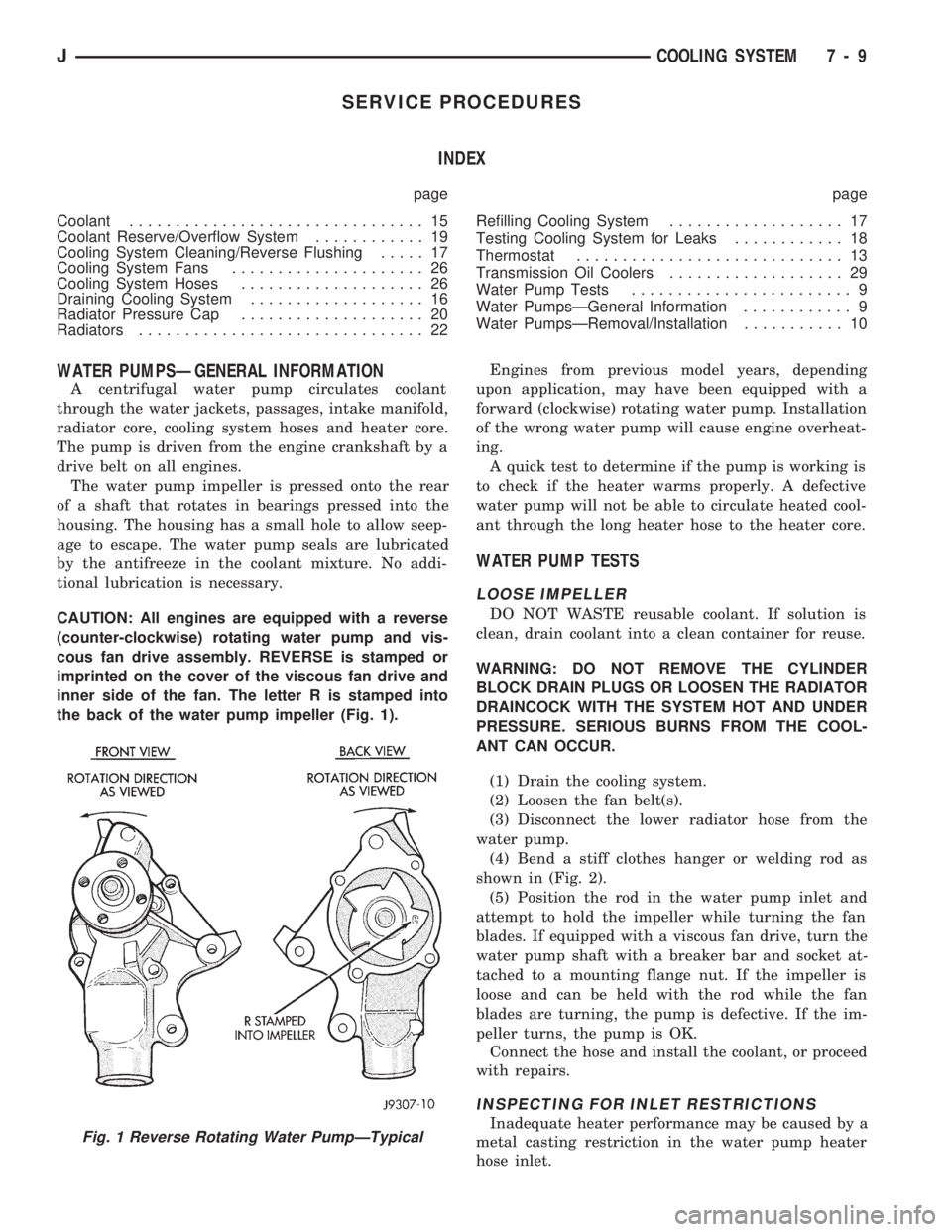
CAUTION: All engines are equipped with a reverse
(counter-clockwise) rotating water pump and vis-
cous fan drive assembly. REVERSE is stamped or
imprinted on the cover of the viscous fan drive and
inner side of the fan. The letter R is stamped into
the back of the water pump impeller (Fig. 1).Engines from previous model years, depending
upon application, may have been equipped with a
forward (clockwise) rotating water pump. Installation
of the wrong water pump will cause engine overheat-
ing.
A quick test to determine if the pump is working is
to check if the heater warms properly. A defective
water pump will not be able to circulate heated cool-
ant through the long heater hose to the heater core.
WATER PUMP TESTS
LOOSE IMPELLER
DO NOT WASTE reusable coolant. If solution is
clean, drain coolant into a clean container for reuse.
WARNING: DO NOT REMOVE THE CYLINDER
BLOCK DRAIN PLUGS OR LOOSEN THE RADIATOR
DRAINCOCK WITH THE SYSTEM HOT AND UNDER
PRESSURE. SERIOUS BURNS FROM THE COOL-
ANT CAN OCCUR.
(1) Drain the cooling system.
(2) Loosen the fan belt(s).
(3) Disconnect the lower radiator hose from the
water pump.
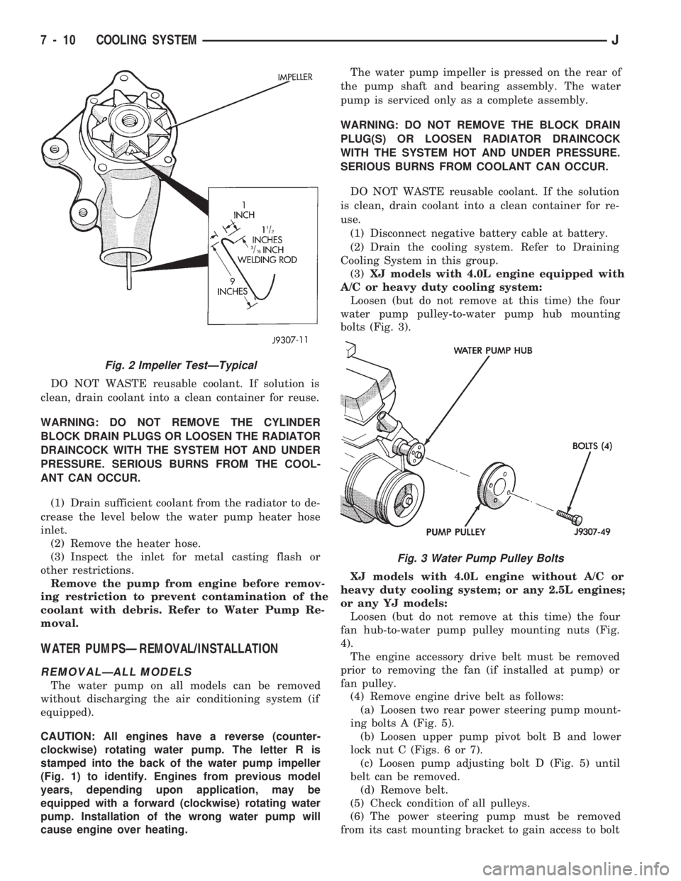
(4) Bend a stiff clothes hanger or welding rod as
shown in (Fig. 2).
(5) Position the rod in the water pump inlet and
attempt to hold the impeller while turning the fan
blades. If equipped with a viscous fan drive, turn the
water pump shaft with a breaker bar and socket at-
tached to a mounting flange nut. If the impeller is
loose and can be held with the rod while the fan
blades are turning, the pump is defective. If the im-
peller turns, the pump is OK.
Connect the hose and install the coolant, or proceed
with repairs.
INSPECTING FOR INLET RESTRICTIONS
Inadequate heater performance may be caused by a
metal casting restriction in the water pump heater
hose inlet.Fig. 1 Reverse Rotating Water PumpÐTypical
JCOOLING SYSTEM 7 - 9
Page 243 of 1784
DO NOT WASTE reusable coolant. If solution is
clean, drain coolant into a clean container for reuse.
WARNING: DO NOT REMOVE THE CYLINDER
BLOCK DRAIN PLUGS OR LOOSEN THE RADIATOR
DRAINCOCK WITH THE SYSTEM HOT AND UNDER
PRESSURE. SERIOUS BURNS FROM THE COOL-
ANT CAN OCCUR.
(1) Drain sufficient coolant from the radiator to de-
crease the level below the water pump heater hose
inlet.
(2) Remove the heater hose.
(3) Inspect the inlet for metal casting flash or
other restrictions.
Remove the pump from engine before remov-
ing restriction to prevent contamination of the
coolant with debris. Refer to Water Pump Re-
moval.
WATER PUMPSÐREMOVAL/INSTALLATION
REMOVALÐALL MODELS
The water pump on all models can be removed
without discharging the air conditioning system (if
equipped).
CAUTION: All engines have a reverse (counter-
clockwise) rotating water pump. The letter R is
stamped into the back of the water pump impeller
(Fig. 1) to identify. Engines from previous model
years, depending upon application, may be
equipped with a forward (clockwise) rotating water
pump. Installation of the wrong water pump will
cause engine over heating.The water pump impeller is pressed on the rear of
the pump shaft and bearing assembly. The water
pump is serviced only as a complete assembly.
WARNING: DO NOT REMOVE THE BLOCK DRAIN
PLUG(S) OR LOOSEN RADIATOR DRAINCOCK
WITH THE SYSTEM HOT AND UNDER PRESSURE.
SERIOUS BURNS FROM COOLANT CAN OCCUR.
DO NOT WASTE reusable coolant. If the solution
is clean, drain coolant into a clean container for re-
use.
(1) Disconnect negative battery cable at battery.
(2) Drain the cooling system. Refer to Draining
Cooling System in this group.
(3)XJ models with 4.0L engine equipped with
A/C or heavy duty cooling system:
Loosen (but do not remove at this time) the four
water pump pulley-to-water pump hub mounting
bolts (Fig. 3).
XJ models with 4.0L engine without A/C or
heavy duty cooling system; or any 2.5L engines;
or any YJ models:
Loosen (but do not remove at this time) the four
fan hub-to-water pump pulley mounting nuts (Fig.
4).
The engine accessory drive belt must be removed
prior to removing the fan (if installed at pump) or
fan pulley.
(4) Remove engine drive belt as follows:
(a) Loosen two rear power steering pump mount-
ing bolts A (Fig. 5).
(b) Loosen upper pump pivot bolt B and lower
lock nut C (Figs. 6 or 7).
(c) Loosen pump adjusting bolt D (Fig. 5) until
belt can be removed.
(d) Remove belt.
(5) Check condition of all pulleys.
(6) The power steering pump must be removed
from its cast mounting bracket to gain access to bolt
Fig. 2 Impeller TestÐTypical
Fig. 3 Water Pump Pulley Bolts
7 - 10 COOLING SYSTEMJ
Page 244 of 1784
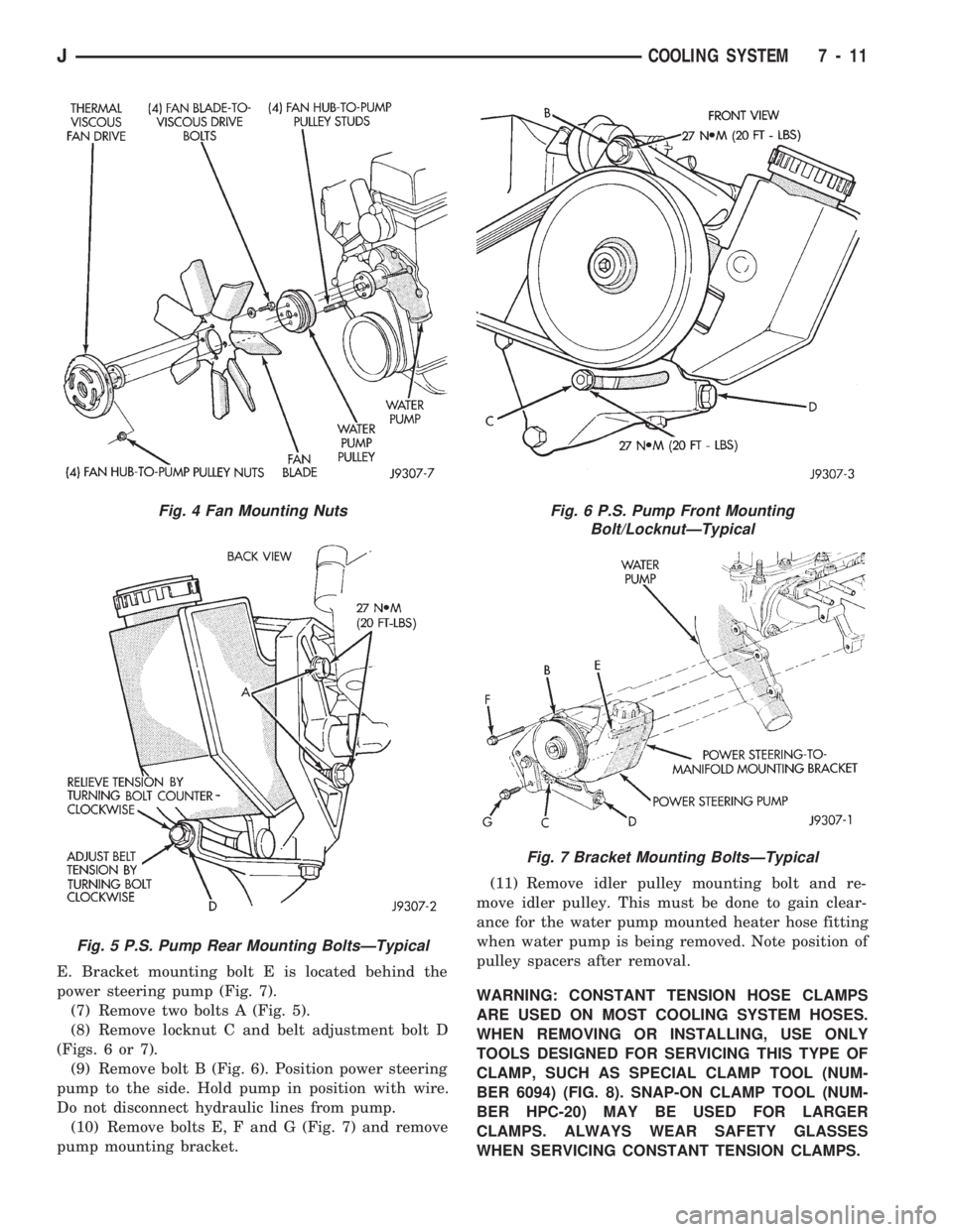
E. Bracket mounting bolt E is located behind the
power steering pump (Fig. 7).
(7) Remove two bolts A (Fig. 5).
(8) Remove locknut C and belt adjustment bolt D
(Figs. 6 or 7).
(9) Remove bolt B (Fig. 6). Position power steering
pump to the side. Hold pump in position with wire.
Do not disconnect hydraulic lines from pump.
(10) Remove bolts E, F and G (Fig. 7) and remove
pump mounting bracket.(11) Remove idler pulley mounting bolt and re-
move idler pulley. This must be done to gain clear-
ance for the water pump mounted heater hose fitting
when water pump is being removed. Note position of
pulley spacers after removal.
WARNING: CONSTANT TENSION HOSE CLAMPS
ARE USED ON MOST COOLING SYSTEM HOSES.
WHEN REMOVING OR INSTALLING, USE ONLY
TOOLS DESIGNED FOR SERVICING THIS TYPE OF
CLAMP, SUCH AS SPECIAL CLAMP TOOL (NUM-
BER 6094) (FIG. 8). SNAP-ON CLAMP TOOL (NUM-
BER HPC-20) MAY BE USED FOR LARGER
CLAMPS. ALWAYS WEAR SAFETY GLASSES
WHEN SERVICING CONSTANT TENSION CLAMPS.
Fig. 4 Fan Mounting Nuts
Fig. 5 P.S. Pump Rear Mounting BoltsÐTypical
Fig. 6 P.S. Pump Front Mounting
Bolt/LocknutÐTypical
Fig. 7 Bracket Mounting BoltsÐTypical
JCOOLING SYSTEM 7 - 11