1994 JEEP CHEROKEE coolant level
[x] Cancel search: coolant levelPage 3 of 1784

ROUTINE SERVICE
The following routine vehicle service is highly rec-
ommended on a monthly basis.
TIRESÐInspect the tires for unusual wear/damage
and determine if the inflation pressure is acceptable
for the vehicle load.
BATTERYÐInspect and clean the terminals.
Tighten the terminals, if necessary.
FLUIDSÐDetermine if the coolant, brake fluid,
power steering, automatic transmission, and clutch
fluid level are acceptable. Add fluid, if necessary.
LIGHTS/ELECTRICALÐTest all the electrically
operated systems in the vehicle for proper operation.
It is also recommended that the engine oil level
and the windshield washer fluid level be deter-
mined (and corrected) during each fuel fill-up.
FUEL REQUIREMENTS
All Jeeptengines require the use of unleaded gas-
oline. In addition, the fuel must have a minimum oc-
tane rating of 87.
CAUTION: UNLEADED FUEL ONLY must be used in
vehicles equipped with a catalyst emission control
system. All vehicles have reminders printed on the
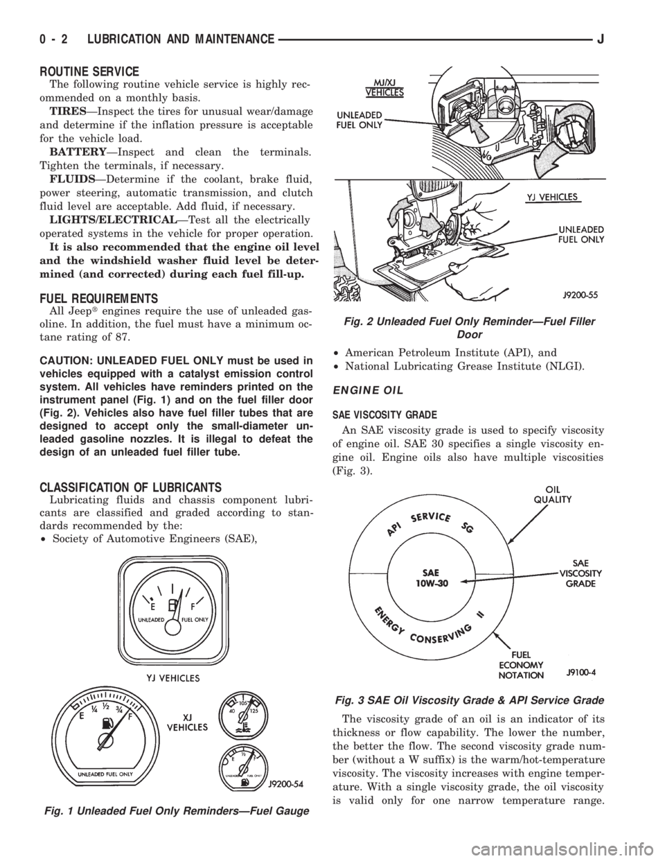
instrument panel (Fig. 1) and on the fuel filler door
(Fig. 2). Vehicles also have fuel filler tubes that are
designed to accept only the small-diameter un-
leaded gasoline nozzles. It is illegal to defeat the
design of an unleaded fuel filler tube.
CLASSIFICATION OF LUBRICANTS
Lubricating fluids and chassis component lubri-
cants are classified and graded according to stan-
dards recommended by the:
²Society of Automotive Engineers (SAE),²American Petroleum Institute (API), and
²National Lubricating Grease Institute (NLGI).
ENGINE OIL
SAE VISCOSITY GRADE
An SAE viscosity grade is used to specify viscosity
of engine oil. SAE 30 specifies a single viscosity en-
gine oil. Engine oils also have multiple viscosities
(Fig. 3).
The viscosity grade of an oil is an indicator of its
thickness or flow capability. The lower the number,
the better the flow. The second viscosity grade num-
ber (without a W suffix) is the warm/hot-temperature
viscosity. The viscosity increases with engine temper-
ature. With a single viscosity grade, the oil viscosity
is valid only for one narrow temperature range.
Fig. 1 Unleaded Fuel Only RemindersÐFuel Gauge
Fig. 2 Unleaded Fuel Only ReminderÐFuel Filler
Door
Fig. 3 SAE Oil Viscosity Grade & API Service Grade
0 - 2 LUBRICATION AND MAINTENANCEJ
Page 6 of 1784

MAINTENANCE SCHEDULES
INTRODUCTION
Chrysler Corporation has compiled recommended
lubrication and maintenance schedules and proce-
dures to help reduce premature wear or failure over
a broad range of operating conditions.
SEVERE SERVICE MAINTENANCE
If the vehicle is involved with a severe driving con-
dition, after each 4 800-km (3,000-miles)/3-month in-
terval. A severe driving condition includes:
²frequent short trip driving less than 24 km (15
miles);
²frequent driving in a dusty environment;
²trailer towing;
²extensive engine idling;
²sustained high-speed operation;
²desert operation;
²frequent starting and stopping;
²cold-climate operation;
²off-road driving; or
²commercial service.
MAINTENANCE SCHEDULES
AT EACH STOP FOR FUEL
²Check engine oil level, add as required.
²
Check windshield washer solvent and add if required.
ONCE A MONTH
²Check tire pressure and look for unusual wear or
damage.
²Inspect battery and clean and tighten terminals as
required.
²Check electrolyte level and add water as needed.
²Check fluid levels of coolant reservoir, power steer-
ing and transmission and add as needed.
²Check all lights and all other electrical items for
correct operation.
²Check rubber seals on each side of the radiator for
proper fit.
7,500 MILES (12 000 KM) OR AT 6 MONTHS
²Check engine coolant level, hoses and clamps.
²Change engine oil.
²Replace engine oil filter.
²Check exhaust system.
²Lubricate steering linkage (4x4 models).
²Lubricate propeller shaft universal joints.
²Rotate Tires.
15,000 MILES (24 000 KM) OR AT 12 MONTHS
²Check engine coolant level, hoses and clamps.
²Change engine oil.
²Replace engine oil filter.
²Check exhaust system.
²Lubricate steering linkage (4x4 models).
²Lubricate propeller shaft universal joints.²Check fluid level in battery.
²Rotate Tires.
22,500 MILES (36 000 KM) OR AT 18 MONTHS
²Check engine coolant level, hoses and clamps.
²Change engine oil.
²Replace engine oil filter.
²Check exhaust system.
²Lubricate steering linkage (4x4 models).
²Lubricate propeller shaft universal joints.
²Rotate Tires.
30,000 MILES (48 000 KM) OR AT 24 MONTHS
²Replace air cleaner filter.
²Replace spark plugs.
²Adjust drive belt.
²Check engine coolant level, hoses and clamps.
²Change engine oil.
²Replace engine oil filter.
²Check exhaust system.
²Lubricate steering linkage (4x4 models).
²Lubricate propeller shaft universal joints.
²Check fluid level in battery.
²Drain and refill automatic transmission.
²Drain and refill transfer case.
²Rotate Tires.
37,500 MILES (60 000 KM) OR AT 30 MONTHS
²Check engine coolant level, hoses and clamps.
²Change engine oil.
²Replace engine oil filter.
²Check exhaust system.
²Lubricate steering linkage (4x4 models).
²Lubricate propeller shaft universal joints.
²Drain and refill manual transmission.
²Rotate Tires.
45,000 MILES (72 500 KM) OR AT 36 MONTHS
²Check engine coolant level, hoses and clamps.
²Change engine oil.
²Replace engine oil filter.
²Check exhaust system.
²Lubricate steering linkage (4x4 models).
²Lubricate propeller shaft universal joints.
²Check fluid level in battery.
²Rotate Tires.
52,500 MILES (84 500 KM) OR AT 42 MONTHS
²Flush and replace engine coolant.
²Check engine coolant system hoses and clamps.
²Change engine oil.
²Replace engine oil filter.
²Check exhaust system.
²Lubricate steering linkage (4x4 models).
²Lubricate propeller shaft universal joints.
²Rotate Tires.
JLUBRICATION AND MAINTENANCE 0 - 5
Page 7 of 1784

60,000 MILES (96 500 KM) OR AT 48 MONTHS.
²Replace air cleaner filter.
²Replace distributor cap and rotor.
²Replace ignition wires.
²Replace spark plugs.
²Adjust or replace drive belt.
²Check engine coolant level, hoses and clamps.
²Change engine oil.
²Replace engine oil filter.
²Check exhaust system.
²Replace fuel filter (not required for Calif. vehicles).
²Lubricate steering linkage (4x4 models).
²Lubricate propeller shaft universal joints.
²Check fluid level in battery.
²Drain and refill automatic transmission.
²Drain and refill transfer case.
²Rotate Tires.
67,500 MILES (108 500 KM) OR AT 54
MONTHS
²Check engine coolant level, hoses and clamps.
²Change engine oil.
²Replace engine oil filter.
²Check exhaust system.
²Lubricate steering linkage (4x4 models).
²Lubricate propeller shaft universal joints.
²Rotate Tires.
75,000 MILES (120 500 KM) OR AT 60
MONTHS
²Check engine coolant level, hoses and clamps.
²Change engine oil.
²Replace engine oil filter.
²Check exhaust system.
²Lubricate steering linkage (4x4 models).
²Lubricate propeller shaft universal joints.
²Drain and refill manual transmission.
²Rotate Tires.
82,500 MILES (133 000 KM) OR AT 66
MONTHS
²Flush and replace engine coolant.
²Check engine coolant system, hoses and clamps.
²Change engine oil.
²Replace engine oil filter.
²Check exhaust system.
²Lubricate steering linkage (4x4 models).
²Lubricate propeller shaft universal joints.
²Rotate Tires.
90,000 MILES (145 000 KM) OR AT 72
MONTHS
²Replace air cleaner filter.
²Replace spark plugs.
²Adjust drive belt.
²Check engine coolant level, hoses and clamps.
²Change engine oil.
²Replace engine oil filter.²Check exhaust system.
²Lubricate steering linkage (4x4 models).
²Lubricate propeller shaft universal joints.
²Check fluid level in battery.
²Drain and refill automatic transmission.
²Drain and refill transfer case.
²Rotate Tires.
97,500 MILES (157 000 KM) OR AT 78
MONTHS
²Check engine coolant level, hoses and clamps.
²Change engine oil.
²Replace engine oil filter.
²Check exhaust system.
²Lubricate steering linkage (4x4 models).
²Lubricate propeller shaft universal joints.
²Rotate Tires.
105,000 MILES (169 000 KM) OR AT 84
MONTHS
²Check engine coolant level, hoses and clamps.
²Change engine oil.
²Replace engine oil filter.
²Check exhaust system.
²Lubricate steering linkage (4x4 models).
²Lubricate propeller shaft universal joints.
²Rotate Tires.
112,500 MILES (181 000 KM) OR AT 90
MONTHS
²Flush and replace engine coolant.
²Check engine coolant system hoses and clamps.
²Change engine oil.
²Replace engine oil filter.
²Check exhaust system.
²Lubricate steering linkage (4x4 models).
²Lubricate propeller shaft universal joints.
²Rotate Tires.
120,000 MILES (193 000 KM) OR AT 96
MONTHS
²Replace air cleaner filter.
²Replace distributor cap and rotor.
²Replace ignition wires.
²Replace spark plugs.
²Adjust or replace drive belt.
²Check engine coolant level, hoses and clamps.
²Change engine oil.
²Replace engine oil filter.
²Check exhaust system.
²Replace fuel filter (not required for Calif. vehicles).
²Lubricate steering linkage (4x4 models).
²Lubricate propeller shaft universal joints.
²Check fluid level in battery.
²Drain and refill automatic transmission.
²Drain and refill transfer case.
²Rotate Tires.
0 - 6 LUBRICATION AND MAINTENANCEJ
Page 14 of 1784

ENGINE MAINTENANCE
INDEX
page page
Accessory Drive Belt...................... 20
Air-Conditioner Compressor/Hoses/Fittings...... 21
Battery................................ 18
Cooling System.......................... 16
Crankcase Ventilation System............... 17
Engine Air Cleaner Filter Element............ 16
Engine Break-In......................... 13
Engine Oil.............................. 13Engine Oil Change and Filter Replacement..... 15
Engine Oil Filter......................... 14
Engine Supports......................... 20
Exhaust System......................... 20
Fuel Usage StatementÐGas Engines......... 17
Ignition Cables, Distributor Cap and Rotor...... 18
Rubber and Plastic Ducts/Hoses/Tubing....... 19
Spark Plugs............................ 18
ENGINE BREAK-IN
After first starting a new engine, allow it to idle
and warm up for at least 15 seconds before shifting
the transmission into a drive gear.
Drive the vehicle at:
²varying speeds less than 80 km/h (50 mph) for the
first 160 km (100 miles), and
²speeds less than 88 km/h (55 mph) for the first 800
km (500 miles).
Avoid driving at full-throttle for extended periods
of time. Also, avoid fast acceleration and sudden
stops.
A special break-in engine oil is not required. The
original oil installed in a vehicle is a quality lubri-
cant. There is no requirement to have the oil
changed or the oil filter replaced until the first
scheduled maintenance interval.
The engine oil, coolant and all the other engine re-
lated fluid levels should be determined on a regular
basis.
ENGINE OIL
SPECIFICATIONS
API SERVICE GRADE
For maximum engine protection during all driving
conditions, install an engine oil that conforms to API
Service Grade. MOPAR Engine Oil conforms to all of
these API Service Grades.
SAE VISCOSITY
SAE designated multi-viscosity grade engine oil is
to protect engines. This type of engine oil can usually
be installed and remain in the engine until the next
scheduled oil change. Select the engine oil viscosity
according to the lowest ambient air temperature ex-
pected before the next scheduled oil change (Fig.1).
Low viscosity engine oil allows easier engine starting
during cold weather. SAE 5W-30 viscosity engine oil
is recommended when the ambient air temperatures
consistently decrease to below 10ÉF (-12ÉC).ENERGY CONSERVING OIL
In selecting the correct API grade and SAE grade,
anENERGY CONSERVINGtype engine oil is also
recommended.
CONTAINER IDENTIFICATION
Standard engine oil notations have been adopted
for selection of engine oil. The notations are located
on side of plastic bottles and on the top of engine oil
cans (Fig. 2).
²The top, outer field contains theAPI Service
Gradenotation for the engine oil.
Fig. 1 Temperature/Engine Oil Viscosity
Fig. 2 Engine Oil Container Standard Notations
JLUBRICATION AND MAINTENANCE 0 - 13
Page 17 of 1784

CAUTION: Do not overfill the engine crankcase with
oil. This will cause oil aeration and result in a de-
crease in the engine oil pressure.
(9) Start the engine and observe the oil pressure
gauge or warning lamp. If the pressure does not in-
crease or the warning lamp does not go out, stop the
engine and determine the cause of the problem.
USED ENGINE OIL DISPOSAL
Care should be exercised when disposing used en-
gine oil after it has been drained from a vehicle en-
gine. Refer to the WARNING listed above.
COOLING SYSTEM
WARNING: USE EXTREME CAUTION WHEN RE-
MOVING THE RADIATOR CAP IF THE ENGINE IS
OPERATING. DO NOT PUT YOUR HANDS NEAR
THE DRIVE BELT(S), PULLEYS OR FAN BLADE. DO
NOT STAND IN A DIRECT LINE WITH THE FAN
BLADE.
RECOMMENDED MAINTENANCE
The engine coolant level should be determined at
least once a month and more often during periods of
hot weather. Add coolant as necessary.
COOLANT LEVEL
With the engine at normal operating temperature,
observe the coolant level in thecoolant recovery bot-
tle. The coolant level must be at least above the ADD
mark and preferably at the FULL mark. Add coolant
to the coolant recovery bottleonly, if necessary.
REQUIRED MAINTENANCE
Check coolant level, and inspect condition of cool-
ing system hoses and clamps after each 12 000-km
(7,500-miles).
Initially, coolant must be drained and cooling sys-
tem flushed and filled after the first 36 months of op-
eration. Thereafter, after each 24-months interval of
vehicle operation.
RECOMMENDED MAINTENANCE
The engine cooling system should be inspected for
proper operation and for component failure at least
every 12 months.
WARNING: IF THE ENGINE HAS BEEN RECENTLY
OPERATED, USE EXTREME CARE WHEN REMOV-
ING THE RADIATOR CAP TO AVOID SCALDING
WITH HOT, PRESSURIZED COOLANT.
For additional information, refer to Section 7, Cool-
ing System.COOLANT FREEZE PROTECTION
Jeeptcooling systems contain a 50/50 mixture of
anti-freeze and distilled water coolant. This is the
recommended coolant mixture for most ambient tem-
peratures. The factory-installed anti-freeze is formu-
lated to prevent corrosion on all cooling system metal
surfaces.
The degree of coolant freeze protection should be
tested every 12 months. If the coolant is contami-
nated orrustyin appearance, cooling system should
be drained and filled with a 50/50 mixture of fresh
coolant. For additional information, refer to Group
7ÐCooling System.
ENGINE AIR CLEANER FILTER ELEMENT
RECOMMENDED MAINTENANCE
Engine performance and fuel economy can be af-
fected by a restricted air cleaner filter. The filter
should be inspected on a regular basis for excessive
air restriction.
If the filter element is saturated with oil, replace
the filter element.
REQUIRED MAINTENANCE
Engine air cleaner filter must be replaced after
each 48 000-km (30,000-miles).
If a vehicle is frequently operated in dusty
areas, the air cleaner filter should be inspected
often.
FILTER ELEMENT SERVICE/REPLACEMENT
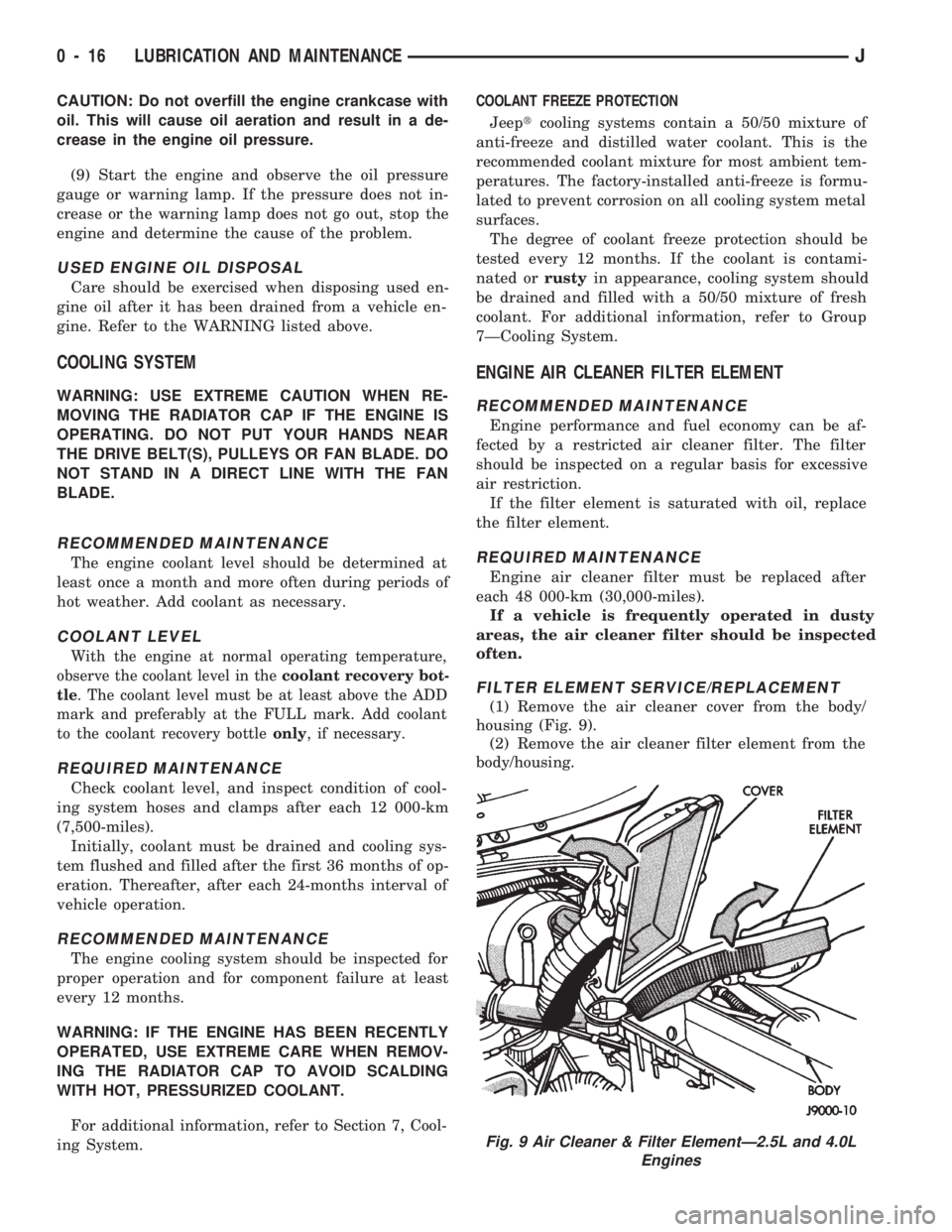
(1) Remove the air cleaner cover from the body/
housing (Fig. 9).
(2) Remove the air cleaner filter element from the
body/housing.
Fig. 9 Air Cleaner & Filter ElementÐ2.5L and 4.0L
Engines
0 - 16 LUBRICATION AND MAINTENANCEJ
Page 106 of 1784

Refer to Group 8D, Ignition System for more crank-
shaft position sensor information.
The engine will not operate if the PCM does not re-
ceive a crankshaft position sensor input.
ENGINE COOLANT TEMPERATURE SENSORÐPCM
INPUT
The coolant temperature sensor is installed in the
thermostat housing (Fig. 10) and protrudes into the
water jacket. The sensor provides an input voltage to
the powertrain control module (PCM) relating cool-
ant temperature. The PCM uses this input along
with inputs from other sensors to determine injector
pulse width and ignition timing. As coolant temper-
ature varies, the coolant temperature sensor's resis-
tance changes. The change in resistance results in a
different input voltage to the PCM.
When the engine is cold, the PCM will operate in
Open Loop cycle. It will demand slightly richer air-
fuel mixtures and higher idle speeds. This is done
until normal operating temperatures are reached.
Refer to Open Loop/Closed Loop Modes of Opera-
tion in this section of the group for more information.
EXTENDED IDLE SWITCHÐPCM INPUT
OPTIONAL POLICE PACKAGE ONLY
The extended idle switch is used to raise the en-
gine idle speed to approximately 1000 rpm. This is
when the shifter is in either the Park or Neutral po-
sition. A rocker-type 2-wire switch (extended idle
switch) is mounted to the instrument panel. This
switch will supply a ground circuit to the powertrain
control module (PCM).The switch is available
only with 4.0L engine when supplied with the
optional police package.
For testing and diagnosis of this switch and its cir-
cuit, refer to the MFI SystemÐGeneral Diagnosis
section of this group.
IGNITION CIRCUIT SENSEÐPCM INPUT
The ignition circuit sense input tells the powertrain
control module (PCM) the ignition switch has ener-
gized the ignition circuit. Refer to the wiring dia-
grams for circuit information.
MANIFOLD ABSOLUTE PRESSURE (MAP)
SENSORÐPCM INPUT
The MAP sensor reacts to absolute pressure in the
intake manifold. It provides an input voltage to the
powertrain control module (PCM). As engine load
changes, manifold pressure varies. The change in
manifold pressure causes MAP sensor voltage to
change. The change in MAP sensor voltage results in
a different input voltage to the PCM. The input volt-
age level supplies the PCM with information about
ambient barometric pressure during engine start-up
(cranking) and engine load while the engine is run-
ning. The PCM uses this input along with inputs
from other sensors to adjust air-fuel mixture.
The MAP sensor is mounted on the dash panel.
The sensor is connected to the throttle body with a
vacuum hose and to the PCM electrically.
Fig. 8 Sensor LocationÐ4.0L Engine
Fig. 9 Sensor LocationÐ2.5L Engine
Fig. 10 Coolant Temperature SensorÐTypical
JFUEL SYSTEM 14 - 21
Page 140 of 1784

REMOVAL
(1) Disconnect the electrical connector from the
sensor.
(2) Remove the sensor from the intake manifold.
INSTALLATION
(1) Install the sensor into the intake manifold.
Tighten the sensor to 28 Nzm (20 ft. lbs.) torque.
(2) Connect the electrical connector to the sensor.
CRANKSHAFT POSITION SENSOR
For description, operation and removal/installation
procedures, refer to Group 8D, Ignition Systems in
this manual.
ENGINE COOLANT TEMPERATURE SENSOR
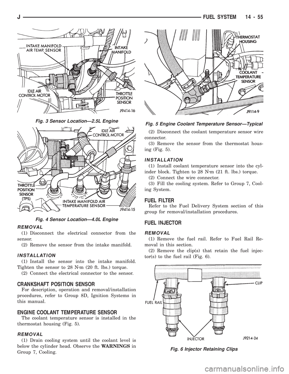
The coolant temperature sensor is installed in the
thermostat housing (Fig. 5).
REMOVAL
(1) Drain cooling system until the coolant level is
below the cylinder head. Observe theWARNINGSin
Group 7, Cooling.(2) Disconnect the coolant temperature sensor wire
connector.
(3) Remove the sensor from the thermostat hous-
ing (Fig. 5).
INSTALLATION
(1) Install coolant temperature sensor into the cyl-
inder block. Tighten to 28 Nzm (21 ft. lbs.) torque.
(2) Connect the wire connector.
(3) Fill the cooling system. Refer to Group 7, Cool-
ing System.
FUEL FILTER
Refer to the Fuel Delivery System section of this
group for removal/installation procedures.
FUEL INJECTOR
REMOVAL
(1) Remove the fuel rail. Refer to Fuel Rail Re-
moval in this section.
(2) Remove the clip(s) that retain the fuel injec-
tor(s) to the fuel rail (Fig. 6).
Fig. 3 Sensor LocationÐ2.5L Engine
Fig. 4 Sensor LocationÐ4.0L Engine
Fig. 5 Engine Coolant Temperature SensorÐTypical
Fig. 6 Injector Retaining Clips
JFUEL SYSTEM 14 - 55
Page 243 of 1784

DO NOT WASTE reusable coolant. If solution is
clean, drain coolant into a clean container for reuse.
WARNING: DO NOT REMOVE THE CYLINDER
BLOCK DRAIN PLUGS OR LOOSEN THE RADIATOR
DRAINCOCK WITH THE SYSTEM HOT AND UNDER
PRESSURE. SERIOUS BURNS FROM THE COOL-
ANT CAN OCCUR.
(1) Drain sufficient coolant from the radiator to de-
crease the level below the water pump heater hose
inlet.
(2) Remove the heater hose.
(3) Inspect the inlet for metal casting flash or
other restrictions.
Remove the pump from engine before remov-
ing restriction to prevent contamination of the
coolant with debris. Refer to Water Pump Re-
moval.
WATER PUMPSÐREMOVAL/INSTALLATION
REMOVALÐALL MODELS
The water pump on all models can be removed
without discharging the air conditioning system (if
equipped).
CAUTION: All engines have a reverse (counter-
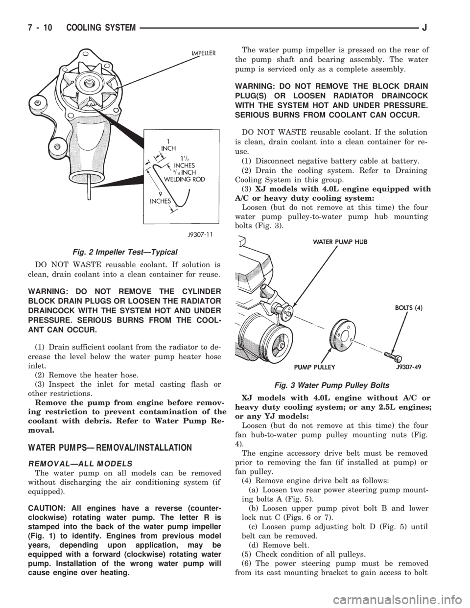
clockwise) rotating water pump. The letter R is
stamped into the back of the water pump impeller
(Fig. 1) to identify. Engines from previous model
years, depending upon application, may be
equipped with a forward (clockwise) rotating water
pump. Installation of the wrong water pump will
cause engine over heating.The water pump impeller is pressed on the rear of
the pump shaft and bearing assembly. The water
pump is serviced only as a complete assembly.
WARNING: DO NOT REMOVE THE BLOCK DRAIN
PLUG(S) OR LOOSEN RADIATOR DRAINCOCK
WITH THE SYSTEM HOT AND UNDER PRESSURE.
SERIOUS BURNS FROM COOLANT CAN OCCUR.
DO NOT WASTE reusable coolant. If the solution
is clean, drain coolant into a clean container for re-
use.
(1) Disconnect negative battery cable at battery.
(2) Drain the cooling system. Refer to Draining
Cooling System in this group.
(3)XJ models with 4.0L engine equipped with
A/C or heavy duty cooling system:
Loosen (but do not remove at this time) the four
water pump pulley-to-water pump hub mounting
bolts (Fig. 3).
XJ models with 4.0L engine without A/C or
heavy duty cooling system; or any 2.5L engines;
or any YJ models:
Loosen (but do not remove at this time) the four
fan hub-to-water pump pulley mounting nuts (Fig.
4).
The engine accessory drive belt must be removed
prior to removing the fan (if installed at pump) or
fan pulley.
(4) Remove engine drive belt as follows:
(a) Loosen two rear power steering pump mount-
ing bolts A (Fig. 5).
(b) Loosen upper pump pivot bolt B and lower
lock nut C (Figs. 6 or 7).
(c) Loosen pump adjusting bolt D (Fig. 5) until
belt can be removed.
(d) Remove belt.
(5) Check condition of all pulleys.
(6) The power steering pump must be removed
from its cast mounting bracket to gain access to bolt
Fig. 2 Impeller TestÐTypical
Fig. 3 Water Pump Pulley Bolts
7 - 10 COOLING SYSTEMJ