1994 JEEP CHEROKEE coolant level
[x] Cancel search: coolant levelPage 259 of 1784
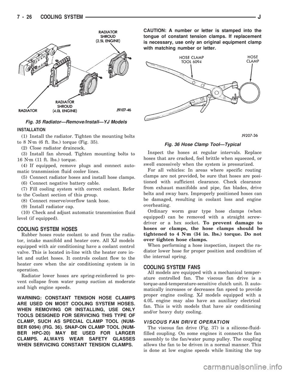
INSTALLATION
(1) Install the radiator. Tighten the mounting bolts
to8Nzm (6 ft. lbs.) torque (Fig. 35).
(2) Close radiator draincock.
(3) Install fan shroud. Tighten mounting bolts to
16 Nzm (11 ft. lbs.) torque.
(4) If equipped, remove plugs and connect auto-
matic transmission fluid cooler lines.
(5) Connect radiator hoses and install hose clamps.
(6) Connect negative battery cable.
(7) Fill cooling system with correct coolant. Refer
to the Coolant section of this group.
(8) Connect reserve/overflow tank hose.
(9) Install radiator cap.
(10) Check and adjust automatic transmission fluid
level (if equipped).
COOLING SYSTEM HOSES
Rubber hoses route coolant to and from the radia-
tor, intake manifold and heater core. All XJ models
equipped with air conditioning have a coolant control
valve. This is located in-line with the heater core in-
let and outlet hoses. It controls coolant flow to the
heater core when the air conditioning system is in
operation.
Radiator lower hoses are spring-reinforced to pre-
vent collapse from water pump suction at moderate
and high engine speeds.
WARNING: CONSTANT TENSION HOSE CLAMPS
ARE USED ON MOST COOLING SYSTEM HOSES.
WHEN REMOVING OR INSTALLING, USE ONLY
TOOLS DESIGNED FOR SERVICING THIS TYPE OF
CLAMP, SUCH AS SPECIAL CLAMP TOOL (NUM-
BER 6094) (FIG. 36). SNAP-ON CLAMP TOOL (NUM-
BER HPC-20) MAY BE USED FOR LARGER
CLAMPS. ALWAYS WEAR SAFETY GLASSES
WHEN SERVICING CONSTANT TENSION CLAMPS.CAUTION: A number or letter is stamped into the
tongue of constant tension clamps. If replacement
is necessary, use only an original equipment clamp
with matching number or letter.
Inspect the hoses at regular intervals. Replace
hoses that are cracked, feel brittle when squeezed, or
swell excessively when the system is pressurized.
For all vehicles: In areas where specific routing
clamps are not provided, be sure that hoses are posi-
tioned with sufficient clearance. Check clearance
from exhaust manifolds and pipe, fan blades, drive
belts and sway bars. Improperly positioned hoses can
be damaged, resulting in coolant loss and engine
overheating.
Ordinary worm gear type hose clamps (when
equipped) can be removed with a straight screw-
driver or a hex socket.To prevent damage to
hoses or clamps, the hose clamps should be
tightened to 4 Nzm (34 in. lbs.) torque. Do not
over tighten hose clamps.
When performing a hose inspection, inspect the ra-
diator lower hose for proper position and condition of
the internal spring.
COOLING SYSTEM FANS
All models are equipped with a mechanical temper-
ature controlled fan. The viscous fan drive is a
torque-and-temperature-sensitive clutch unit. It auto-
matically increases or decreases fan speed to provide
proper engine cooling. XJ models equipped with a
4.0L engine may also have an auxiliary electrical
fan. This is with models that have air conditioning
and/or heavy duty cooling.
VISCOUS FAN DRIVE OPERATION
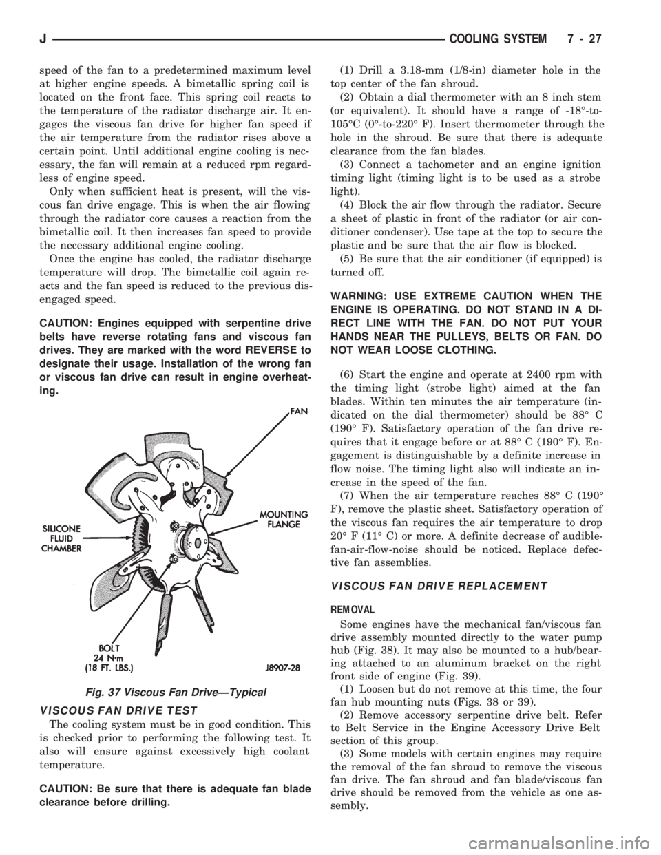
The viscous fan drive (Fig. 37) is a silicone-fluid-
filled coupling. On some engines it connects the fan
assembly to the fan/water pump pulley. The coupling
allows the fan to be driven in a normal manner. This
is done at low engine speeds while limiting the top
Fig. 35 RadiatorÐRemove/InstallÐYJ Models
Fig. 36 Hose Clamp ToolÐTypical
7 - 26 COOLING SYSTEMJ
Page 260 of 1784
speed of the fan to a predetermined maximum level
at higher engine speeds. A bimetallic spring coil is
located on the front face. This spring coil reacts to
the temperature of the radiator discharge air. It en-
gages the viscous fan drive for higher fan speed if
the air temperature from the radiator rises above a
certain point. Until additional engine cooling is nec-
essary, the fan will remain at a reduced rpm regard-
less of engine speed.
Only when sufficient heat is present, will the vis-
cous fan drive engage. This is when the air flowing
through the radiator core causes a reaction from the
bimetallic coil. It then increases fan speed to provide
the necessary additional engine cooling.
Once the engine has cooled, the radiator discharge
temperature will drop. The bimetallic coil again re-
acts and the fan speed is reduced to the previous dis-
engaged speed.
CAUTION: Engines equipped with serpentine drive
belts have reverse rotating fans and viscous fan
drives. They are marked with the word REVERSE to
designate their usage. Installation of the wrong fan
or viscous fan drive can result in engine overheat-
ing.
VISCOUS FAN DRIVE TEST
The cooling system must be in good condition. This
is checked prior to performing the following test. It
also will ensure against excessively high coolant
temperature.
CAUTION: Be sure that there is adequate fan blade
clearance before drilling.(1) Drill a 3.18-mm (1/8-in) diameter hole in the
top center of the fan shroud.
(2) Obtain a dial thermometer with an 8 inch stem
(or equivalent). It should have a range of -18É-to-
105ÉC (0É-to-220É F). Insert thermometer through the
hole in the shroud. Be sure that there is adequate
clearance from the fan blades.
(3) Connect a tachometer and an engine ignition
timing light (timing light is to be used as a strobe
light).
(4) Block the air flow through the radiator. Secure
a sheet of plastic in front of the radiator (or air con-
ditioner condenser). Use tape at the top to secure the
plastic and be sure that the air flow is blocked.
(5) Be sure that the air conditioner (if equipped) is
turned off.
WARNING: USE EXTREME CAUTION WHEN THE
ENGINE IS OPERATING. DO NOT STAND IN A DI-
RECT LINE WITH THE FAN. DO NOT PUT YOUR
HANDS NEAR THE PULLEYS, BELTS OR FAN. DO
NOT WEAR LOOSE CLOTHING.
(6) Start the engine and operate at 2400 rpm with
the timing light (strobe light) aimed at the fan
blades. Within ten minutes the air temperature (in-
dicated on the dial thermometer) should be 88É C
(190É F). Satisfactory operation of the fan drive re-
quires that it engage before or at 88É C (190É F). En-
gagement is distinguishable by a definite increase in
flow noise. The timing light also will indicate an in-
crease in the speed of the fan.
(7) When the air temperature reaches 88É C (190É
F), remove the plastic sheet. Satisfactory operation of
the viscous fan requires the air temperature to drop
20É F (11É C) or more. A definite decrease of audible-
fan-air-flow-noise should be noticed. Replace defec-
tive fan assemblies.
VISCOUS FAN DRIVE REPLACEMENT
REMOVAL
Some engines have the mechanical fan/viscous fan
drive assembly mounted directly to the water pump
hub (Fig. 38). It may also be mounted to a hub/bear-
ing attached to an aluminum bracket on the right
front side of engine (Fig. 39).
(1) Loosen but do not remove at this time, the four
fan hub mounting nuts (Figs. 38 or 39).
(2) Remove accessory serpentine drive belt. Refer
to Belt Service in the Engine Accessory Drive Belt
section of this group.
(3) Some models with certain engines may require
the removal of the fan shroud to remove the viscous
fan drive. The fan shroud and fan blade/viscous fan
drive should be removed from the vehicle as one as-
sembly.
Fig. 37 Viscous Fan DriveÐTypical
JCOOLING SYSTEM 7 - 27
Page 319 of 1784
sensor voltage to change. This change results in a
different input voltage to the PCM. The input volt-
age level supplies the PCM with information. This
relates to ambient barometric pressure during engine
start-up (cranking) and to engine load while the en-
gine is running. The PCM uses this input, along with
inputs from other sensors, to adjust air-fuel mixture.
For more information, refer to Group 14, Fuel Sys-
tem.
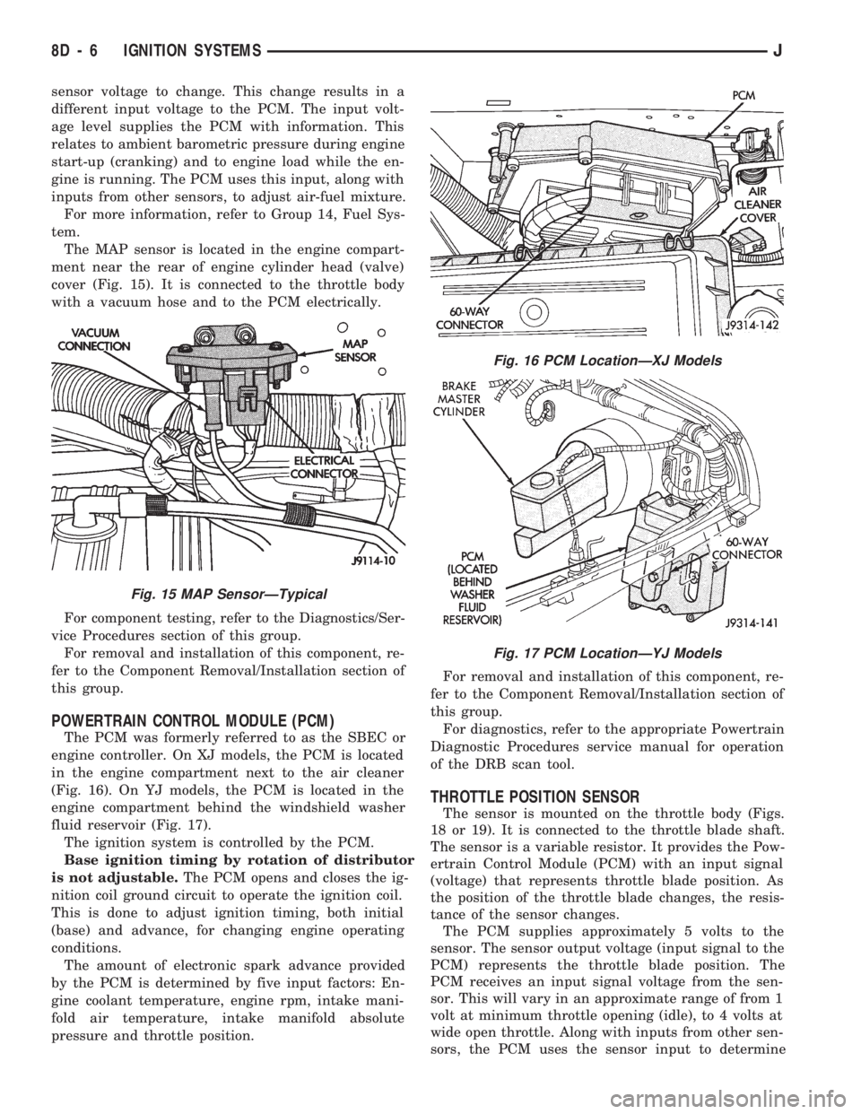
The MAP sensor is located in the engine compart-
ment near the rear of engine cylinder head (valve)
cover (Fig. 15). It is connected to the throttle body
with a vacuum hose and to the PCM electrically.
For component testing, refer to the Diagnostics/Ser-
vice Procedures section of this group.
For removal and installation of this component, re-
fer to the Component Removal/Installation section of
this group.
POWERTRAIN CONTROL MODULE (PCM)
The PCM was formerly referred to as the SBEC or
engine controller. On XJ models, the PCM is located
in the engine compartment next to the air cleaner
(Fig. 16). On YJ models, the PCM is located in the
engine compartment behind the windshield washer
fluid reservoir (Fig. 17).
The ignition system is controlled by the PCM.
Base ignition timing by rotation of distributor
is not adjustable.The PCM opens and closes the ig-
nition coil ground circuit to operate the ignition coil.
This is done to adjust ignition timing, both initial
(base) and advance, for changing engine operating
conditions.
The amount of electronic spark advance provided
by the PCM is determined by five input factors: En-
gine coolant temperature, engine rpm, intake mani-
fold air temperature, intake manifold absolute
pressure and throttle position.For removal and installation of this component, re-
fer to the Component Removal/Installation section of
this group.
For diagnostics, refer to the appropriate Powertrain
Diagnostic Procedures service manual for operation
of the DRB scan tool.
THROTTLE POSITION SENSOR
The sensor is mounted on the throttle body (Figs.
18 or 19). It is connected to the throttle blade shaft.
The sensor is a variable resistor. It provides the Pow-
ertrain Control Module (PCM) with an input signal
(voltage) that represents throttle blade position. As
the position of the throttle blade changes, the resis-
tance of the sensor changes.
The PCM supplies approximately 5 volts to the
sensor. The sensor output voltage (input signal to the
PCM) represents the throttle blade position. The
PCM receives an input signal voltage from the sen-
sor. This will vary in an approximate range of from 1
volt at minimum throttle opening (idle), to 4 volts at
wide open throttle. Along with inputs from other sen-
sors, the PCM uses the sensor input to determine
Fig. 15 MAP SensorÐTypical
Fig. 16 PCM LocationÐXJ Models
Fig. 17 PCM LocationÐYJ Models
8D - 6 IGNITION SYSTEMSJ
Page 335 of 1784
REMOVALÐALL ENGINES
(1) Near the rear of the intake manifold, discon-
nect the pigtail harness (on the sensor) from the
main electrical harness.
(2) Remove the nut holding sensor wire clip to fuel
rail mounting stud.
(3) Depending upon application, remove either the
sensor mounting bolt(s) or nuts.
(4) Remove the sensor.
(5) Remove clip from sensor wire harness.
INSTALLATIONÐALL EXCEPT YJ MODELS
WITH 4.0L ENGINE AND AUTOMATIC
TRANSMISSION
(1) Install the sensor flush against the opening in
the transmission housing.
(2) Install and tighten the two sensor mounting
bolts (or nuts) to 19 Nzm (14 ft. lbs.) torque.
CAUTION: On some models, two bolts used to se-
cure the sensor to the transmission. These bolts
are specially machined to correctly space the unit
to the flywheel. Do not attempt to install any other
bolts.
(3) Connect the electrical connector to the sensor.
(4) Install clip on sensor wire harness.
(5) Install clip over fuel rail mounting stud. Install
clip mounting nut.
INSTALLATIONÐYJ MODELS WITH 4.0L
ENGINE AND AUTOMATIC TRANSMISSION
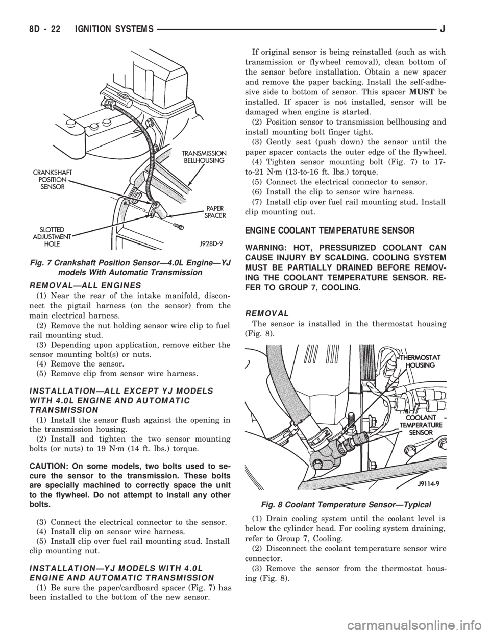
(1) Be sure the paper/cardboard spacer (Fig. 7) has
been installed to the bottom of the new sensor.If original sensor is being reinstalled (such as with
transmission or flywheel removal), clean bottom of
the sensor before installation. Obtain a new spacer
and remove the paper backing. Install the self-adhe-
sive side to bottom of sensor. This spacerMUSTbe
installed. If spacer is not installed, sensor will be
damaged when engine is started.
(2) Position sensor to transmission bellhousing and
install mounting bolt finger tight.
(3) Gently seat (push down) the sensor until the
paper spacer contacts the outer edge of the flywheel.
(4) Tighten sensor mounting bolt (Fig. 7) to 17-
to-21 Nzm (13-to-16 ft. lbs.) torque.
(5) Connect the electrical connector to sensor.
(6) Install the clip to sensor wire harness.
(7) Install clip over fuel rail mounting stud. Install
clip mounting nut.
ENGINE COOLANT TEMPERATURE SENSOR
WARNING: HOT, PRESSURIZED COOLANT CAN
CAUSE INJURY BY SCALDING. COOLING SYSTEM
MUST BE PARTIALLY DRAINED BEFORE REMOV-
ING THE COOLANT TEMPERATURE SENSOR. RE-
FER TO GROUP 7, COOLING.
REMOVAL
The sensor is installed in the thermostat housing
(Fig. 8).
(1) Drain cooling system until the coolant level is
below the cylinder head. For cooling system draining,
refer to Group 7, Cooling.
(2) Disconnect the coolant temperature sensor wire
connector.
(3) Remove the sensor from the thermostat hous-
ing (Fig. 8).
Fig. 7 Crankshaft Position SensorÐ4.0L EngineÐYJ
models With Automatic Transmission
Fig. 8 Coolant Temperature SensorÐTypical
8D - 22 IGNITION SYSTEMSJ
Page 349 of 1784
other side. When coolant temperature is too high the
switch closes providing a path to ground, and the indi-
cator bulb lights.
TACHOMETER
The tachometer displays the engine speed (RPM).
With the engine running, the tachometer receives an
engine speed signal from the Powertrain Control
Module pin 43 (values shown in Specifications chart).
SPEEDOMETER/ODOMETER SYSTEM
The speedometer/odometer system consists of an elec-
tric speedometer and pushbutton reset odometer
mounted in the cluster. The system also includes the
wire harness from the cluster to the vehicle speed sen-
sor at the transmission, and the adapter and pinion in
the transmission. A signal is sent from a transmission
mounted vehicle speed sensor to the speedometer/odom-
eter circuitry through the wiring harness. Refer to
Group 21 - Transmission for selecting the proper pinion,
and selecting and indexing the proper adapter.
FUEL GAUGE
The fuel gauge pointer position is controlled by a
magnetic field created by electrical current flow through
the coils within the gauge. A change in current flow will
change the magnetic field which changes the pointer po-
sition. The fuel level sender is a variable resistor that
changes electrical resistance with a change of the level
of fuel in the tank (values shown in Specifications
chart).
LOW FUEL WARNING LAMP
The low fuel warning lamp will light when the fuel
level falls below approximately 4 gallons. A low fuel
warning module controls when the lamp will light.
When the module senses 66.5 ohms or less from the
fuel level sender for 10 continuous seconds, the lamp
will light. The lamp will remain on until the module
senses 63.5 ohms or more from the fuel level sender
for 20 continuous seconds.
UPSHIFT INDICATOR LAMP
Vehicles equipped with manual transmissions have an
optional upshift indicator lamp. The lamp is controlled
by the Powertrain Control Module. The lamp lights to
indicate when the driver should shift to the next high-
est gear for best fuel economy. The Powertrain Control
Module will turn the lamp off after 3 to 5 seconds if the
upshift is not performed. The lamp will remain off until
the vehicle stops accelerating and is brought back to the
range of lamp operation or shifted into another gear.
The indicator lamp is normally illuminated when
the ignition switch is turned ON and is turned off
when the engine is started. The lamp will be lighted
during engine operation according to engine speed
and load.
BRAKE INDICATOR LAMP
The brake indicator lamp warns the driver that the
parking brake is applied or that hydraulic pressure in
the split brake system is unequal.
Voltage is supplied through the brake indicator
bulb to 3 switches. A path to ground for the current
is available if:
²The brake warning switch is closed (with unequal
brake system hydraulic pressures), or
²
The ignition switch is in the START position (to test
the bulb), or
²The park brake switch is closed (with the parking
brake applied).
ANTI-LOCK BRAKE SYSTEM (ABS) INDICATOR
LAMP
The anti-lock brake system (ABS) lamp lights to in-
dicate a system self-check is in process at vehicle
start-up. If light remains on after start-up or comes
on and stays on while driving, it may indicate that
the ABS system has detected a malfunction or has
become inoperative.
4WD INDICATOR LAMP
COMMAND-TRAC 4WD
The PART TIME lamp lights when the vehicle is en-
gaged in four-wheel drive mode. Voltage is supplied to
one side of the indicator bulb. A switch in the transfer
case area is connected to the other side of the indicator
bulb. When the switch is closed, a path to ground is pro-
vided and the indicator bulb lights.
SELECT-TRAC 4WD
The four-wheel drive icon or FULL TIME lamp
lights when the vehicle is engaged in full time four-
wheel drive mode. The PART TIME lamp lights when
the vehicle is in part time four-wheel drive mode.
Voltage is supplied to one side of the indicators.
Switches in the transfer case area are connected to
the other side of the indicator bulbs. When a switch
is closed, a path to ground is provided and the indi-
cator bulb lights.
MALFUNCTION INDICATOR LAMP (CHECK ENGINE)
The Malfunction Indicator Lamp (Check Engine)
lights each time the ignition switch is turned ON and
stays on for 3 seconds as a bulb test.
If the PCM receives an incorrect signal or no signal
from certain sensors or emission related systems the
lamp is turned on (pin 32 of PCM). This is a warning
that the PCM has recorded a system or sensor mal-
function. In some cases when a diagnostic trouble
code is declared the PCM will go into a limp-in mode
in an attempt to keep the system operating. It sig-
nals an immediate need for service.
The lamp also can be used to display diagnostic
trouble codes (DTC). Cycle the ignition switch ON,
OFF, ON, OFF, ON within 5 seconds. This will allow
any trouble codes stored in the PCM memory to be
displayed in a series of flashes representing digits.
8E - 2 XJ INSTRUMENT PANEL AND GAUGESJ
Page 643 of 1784
Wiring Diagram Name Sheet Number
Engine Block Heater.........................37
Wall Plug................................37
Engine Coolant Temperature Sending Unit.............24
Engine Coolant Temperature Sensor..............14,19
Engine Coolant Temperature Switch.................24
Engine Oil Pressure and Temperature System..........24
Engine Coolant Temperature Switch...............24
Engine Oil Pressure Sending Unit................24
Engine Oil Pressure Switch....................24
Engine Starter Motor..........................7,8
Engine Starter Relay.........................3,7,8
Engine Starter System (2.5L)......................7
Battery..................................7
Engine Starter Motor.........................7
Engine Starter Relay..........................7
Park/Neutral Position Switch....................7
Engine Starter System (4.OL).....................8
Battery..................................8
Engine Starter Motor.........................8
Engine Starter Relay..........................8
Fan Control Relay............................23
Fog Lamp Illumination.......................42,47
Fog Lamps..............................39,40
Fog Lamp Switch............................42
Front Axle Switch..........................26,27
Front Door Lock and Window Switch Functions.........87
Front End Lighting..........................39,40
High Beam Relay...........................40
Left Fog Lamp.............................39
Left Headlamp.............................39
Left Park/Turn Signal Lamp....................39
Left Side Marker Lamp.......................39
Park Lamp Relay...........................39
Right Fog Lamp............................40
Right Headlamp............................40
Right Park/Turn Signal Lamp...................40
Right Side Marker Lamp......................40
Front Washer Pump.........................63,64
Front Wiper Motor..........................63,64
Front Wipers/Washer (Intermittent).................64
Front Washer Pump.........................64
Front Wiper Motor..........................64
Wiper/Washer Switch........................64
Intermittent Wiper Module.....................64
Front Wiper/Washer (Standard)....................63
Front Washer Pump.........................63
Front Wiper Motor..........................63
Wiper/Washer Switch........................63
Fuel Injection Ignition System (2.5L)......11,12,13,14,15,16
Automatic Shut Down Relay....................12
Camshaft Position Sensor.....................11
Crankshaft Position Sensor.....................11
Data Link Connector.........................16
Distributor Ignition Coil.......................16
Engine Coolant Temperature Sensor...............14
Fuel Pump Relay...........................12
Heated Oxygen Sensor.......................13
Idle Air Control Motor........................15Wiring Diagram Name Sheet Number
Injectors.................................15
Intake Air Temperature Sensor..................14
MAP Sensor..............................14
Power Steering Pressure Switch.................15
Powertrain Control Module...........11,12,13,14,15,16
Throttle Position Sensor......................14
Vehicle Speed Sensor........................11
Fuel Injection Ignition System (4.OL)......17,18,19,20,21,22
Automatic Shut Down Relay....................17
Camshaft Position Sensor.....................20
Crankshaft Position Sensor.....................20
Data Link Connector.........................18
Distributor Ignition Coil.......................18
Engine Coolant Temperature Sensor...............19
Fuel Pump Relay...........................17
Heated Oxygen Sensor.......................21
Idle Air Control Motor........................22
Intake Air Temperature Sensor..................19
Injectors.................................22
MAP Sensor..............................19
Powertrain Control Module...........17,18,19,20,21,22
Throttle Position Sensor......................19
Vehicle Speed Sensor........................20
Fuel Injector(s)............................15,22
Fuel Pump Relay.........................3,12,17
Fuel Tank Level Gauge Sending Unit................90
Fuel Tank System..........................89,90
Ballast Resistor............................89
Fuel Tank Level Gauge Sending Unit..............90
Full Time Indicator Lamp.....................57,58
Fuse Application Chart.........................1,2
Fuse Panel..............................99,100
Fuses
F1 ....................................3,4
F2 ................................3,4,12,17
F3 ....................................3,4
F4 ....................................3,4
F5 ....................................3,4
F6 ....................................3,4
F7 ....................................3,4
F8 ....................................3,4
F9 ....................................3,4
F10 ...................................3,4
F11 ...................................3,4
F12 ...................................3,4
F13 ...................................3,4
F14 ...................................3,4
F15 ...................................3,4
F16 ...................................3,4
Fuse #1..............................2,10,65
Fuse #2.............................2,9,37,71
Fuse #4................................1,41
Fuse #5..........................2,63,64,68,70
Fuse #7..............................2,10,32
Fuse #8..............................2,45,66
Fuse #9...............................1,4,49
Fuse #11.............................1,43,83
Fuse #13.............................1,43,83
8W - 150 WIRING DIAGRAMSJ
Page 644 of 1784
Wiring Diagram Name Sheet Number
Fuse #15...............................1,41
Fuse #17...........................2,10,55,74
Fuse #18...............................1,66
Fuse #19.............................1,41,47
Gauges
Engine Coolant Temperature Gauge...........59,60,61
Engine Oil Pressure Gauge.................59,60,61
Fuel Gauge...........................59,60,61
G Sensor..................................30
Generator.................................5,6
Glove Box Lamp.............................49
Hazard Flasher............................35,46
Headlamp Delay Module........................43
Headlamp Dimmer Switch.......................41
Headlamp Switch...........................41,42
Fog Lamp Illumination........................42
Fog Lamp Switch...........................42
Headlamp Dimmer Switch.....................41
Headlamp Switch...........................41
Headlamps...............................39,40
Heat Mode Select Switch.......................68
Heated Oxygen Sensor.......................13,21
Heated Rear Window..........................66
Relay...................................66
Grid...................................66
Switch..................................66
Heated Rear Window Switch Lamp.................47
Heater A/C Panel Lamp........................47
Heater and A/C System......................69,70
A/C Mode Selector Switch.....................70
A/C Compressor Clutch.......................69
A/C Compressor Clutch Relay...................69
A/C Heater Blower Motor......................70
A/C Thermostat............................69
A/C Low Pressure Switch.....................69
Blower Resistor............................70
Blower Switch.............................70
Powertrain Control Module.....................69
Heat Mode Select Switch.......................68
Heater Blower Motor..........................68
Heater,Engine Block...........................37
Heater System..............................68
Blower Resistor............................68
Blower Switch.............................68
Heater Blower Motor.........................68
Heater Mode Select Switch....................68
Heavy Duty Cooling 4.OL.......................23
Fan Control Relay...........................23
Powertrain Control Module.....................23
Radiator Fan Motor.........................23
High Beam Indicator Lamp..................59,60,61
High Beam Relay............................40
Hi-Line Instrument Cluster.......................61
Horn Brush/Slip Ring..........................34
Horn Relay................................34
Horn Switch................................34
Horns....................................34
Hydraulic Actuation Unit, ABS....................33Wiring Diagram Name Sheet Number
Idle Air Control Motor.......................15,22
Ignition Key Warning Switch.....................74
Ignition Switch..............................2,9
Ignition System............................9,10
Injectors................................15,22
In Line Circuit Breaker..........................2
Instrument Cluster............................55
Powertrain Control Module.....................55
Washer Fluid Level Switch.....................55
Instrument Cluster (Hi-Line)......................61
Instrument Cluster (Lo-Line).....................60
Instrument Cluster (Standard)....................59
Instrument Cluster Connector..................55,108
Instrument Cluster Printed Circuit Board (W/ABS).......57
Instrument Cluster Printed Circuit Board (W/O ABS)......58
Instrument Cluster Indicators.....................56
Instrument Panel Ground.......................62
Instrument Panel Illumination...................47,48
Ashtray Lamp.............................48
Cigar Lighter Lamp..........................48
Fog Lamp Illumination........................47
Heater A/C Panel Lamp.......................47
Heater Rear Window Switch Lamp................47
Rear Wiper Wash Switch Lamp..................47
Transfer Case Lamp.........................48
Transmission Range Switch Lamp................48
Intake Air Temperature Sensor..................14,19
Intermittent Front Wipers/Washers.................64
Intermittent Wiper Module.......................64
Lamps
ABS Green Indicator Lamp.....................57
ABS Red Indicator Lamp......................57
Ashtray Lamp.............................48
Cargo Lamp..............................50
Center High Mounted Stop Lamps................98
Cigar Lighter Lamp..........................48
Dome Lamp..............................51
Dome/Reading Lamp.........................51
Fog Lamp Illumination........................47
4WD Indicator Lamp.....................26,57,58
Full Time Indicator Lamp....................57,58
Glove Box Lamp...........................49
Heated Rear Window Switch Lamp...............47
Heater A/C Panel Lamp.......................47
High Beam Indicator Lamp.................59,60,61
Indicator Lamp 4WD.......................57,58
Instrument Cluster Illumination Lamps.........59,60,61
Left Back-Up Lamp........................91,93
Left Courtesy Lamp.........................49
Left Fog Lamp.............................39
Left Headlamp.............................39
Left Park/Turn Signal Lamp....................39
Left Side Marker Lamp (Front)..................39
Left Side Marker Lamp (Rear)................91,93
Left Tail/Stop Lamp.......................91,93
Left Turn Indicator Lamp..................59,60,61
Left Turn Lamp (Amber)....................91,93
Left Vanity Lamp...........................51
JWIRING DIAGRAMS 8W - 151
Page 847 of 1784
If a cylinder is leaking combustion pressure into
the water jacket, the tester pointer will pulsate with
every combustion stroke of the cylinder.
CYLINDER COMBUSTION PRESSURE LEAKAGE
TEST
The combustion pressure leakage test provides an
accurate means for determining engine condition.
Combustion pressure leakage testing will detect:
²Exhaust and intake valve leaks (improper seat-
ing).
²Leaks between adjacent cylinders or into water
jacket.
²Any causes for combustion/compression pressure
loss.
WARNING: DO NOT REMOVE THE RADIATOR CAP
WITH THE SYSTEM HOT AND UNDER PRESSURE
BECAUSE SERIOUS BURNS FROM COOLANT CAN
OCCUR.
Check the coolant level and fill as required. DO
NOT install the radiator cap.
Start and operate the engine until it attains nor-
mal operating temperature, then turn the engine
OFF.Remove the spark plugs.
Remove the oil filler cap.
Remove the air cleaner.
Calibrate the tester according to the manufactur-
er's instructions. The shop air source for testing
should maintain 483 kPa (70 psi) minimum, 1 379
kPa (200 psi) maximum and 552 kPa (80 psi) recom-
mended.
Perform the test procedures on each cylinder ac-
cording to the tester manufacturer's instructions.
While testing, listen for pressurized air escaping
through the throttle body, tailpipe and oil filler cap
opening. Check for bubbles in the radiator coolant.
All gauge pressure indications should be equal,
with no more than 25% leakage.
FOR EXAMPLE:At 552 kPa (80 psi) input pres-
sure, a minimum of 414 kPa (60 psi) should be main-
tained in the cylinder.
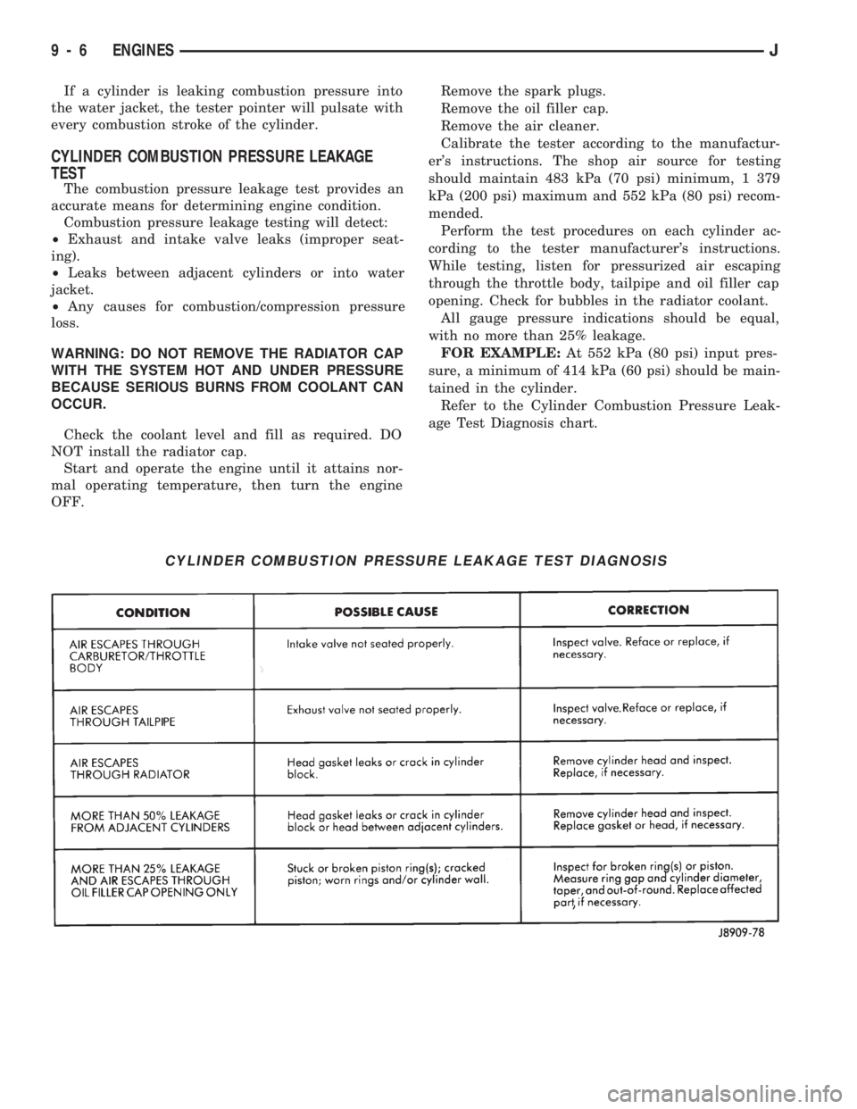
Refer to the Cylinder Combustion Pressure Leak-
age Test Diagnosis chart.
CYLINDER COMBUSTION PRESSURE LEAKAGE TEST DIAGNOSIS
9 - 6 ENGINESJ