1994 JEEP CHEROKEE oil dipstick
[x] Cancel search: oil dipstickPage 15 of 1784

²The center field contains theSAE viscosity
gradenotation for the engine oil.
²The lower, outer field contains either theEN-
ERGY CONSERVINGor theENERGY CON-
SERVING IInotation for the engine oil.
CAUTION: Non-detergent engine oil or straight-min-
eral oil must never be used to lubricate a JeepTen-
gine. These type of oils will not provide proper
engine lubrication and can result in engine damage.
LEVEL INDICATOR (DIPSTICK)
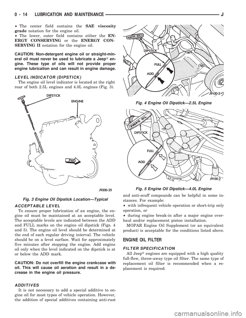
The engine oil level indicator is located at the right
rear of both 2.5L engines and 4.0L engines (Fig. 3).
ACCEPTABLE LEVEL
To ensure proper lubrication of an engine, the en-
gine oil must be maintained at an acceptable level.
The acceptable levels are indicated between the ADD
and FULL marks on the engine oil dipstick (Figs. 4
and 5). The engine oil level should be determined at
the end of each regular driving interval. The vehicle
should be on a level surface. Wait for approximately
five minutes after stopping the engine. Add engine
oil only when the level indicated on the dipstick is at
or below the ADD mark.
CAUTION: Do not overfill the engine crankcase with
oil. This will cause oil aeration and result in a de-
crease in the engine oil pressure.
ADDITIVES
It is not necessary to add a special additive to en-
gine oil for most types of vehicle operation. However,
the addition of special additives containing anti-rustand anti-scuff compounds can be helpful in some in-
stances. For example:
²with infrequent vehicle operation or short-trip only
operation, or
²during engine break-in after a major engine over-
haul and/or replacement piston installation.
MOPAR Engine Oil Supplement (or an equivalent
product) is acceptable for the conditions listed above.
ENGINE OIL FILTER
FILTER SPECIFICATION
All Jeeptengines are equipped with a high quality
full-flow, throw-away type oil filter. The same type of
replacement oil filter is recommended when a re-
placement is required.
Fig. 3 Engine Oil Dipstick LocationÐTypical
Fig. 4 Engine Oil DipstickÐ2.5L Engine
Fig. 5 Engine Oil DipstickÐ4.0L Engine
0 - 14 LUBRICATION AND MAINTENANCEJ
Page 16 of 1784

ENGINE OIL CHANGE AND FILTER REPLACEMENT
WARNING: CARE SHOULD BE TAKEN WHEN
CHANGING OIL. PROTECTIVE CLOTHING AND
GLOVES SHOULD BE WORN. EXPOSED SKIN
SHOULD BE WASHED WITH SOAP AND WATER TO
REMOVE ANY ENGINE OIL. DO NOT USE GASO-
LINE, THINNER, OR SOLVENTS TO REMOVE EN-
GINE OIL FROM SKIN.
REQUIRED MAINTENANCE
With normal driving conditions, engine oil and fil-
ter must be changed after each 12 000-km (7,500-
miles)/12-month interval. If the vehicle is involved
with a severe driving condition, after each 4 800-km
(3,000-miles)/3-month interval. A severe driving con-
dition includes:
²frequent short trip driving less than 24 km (15
miles);
²frequent driving in a dusty environment;
²trailer towing;
²extensive engine idling;
²sustained high-speed operation;
²desert operation;
²frequent starting and stopping;
²cold-climate operation;
²off-road driving; or
²commercial service.
OIL CHANGE AND FILTER REPLACEMENT
(1) Drain the engine oil from the crankcase. Wait
until after the engine has attained the normal oper-
ating temperature to ensure complete drainage of oil.
(2) Install the drain-hole plug with a replacement
gasket.
The oil filter should be replaced during every
engine oil change.
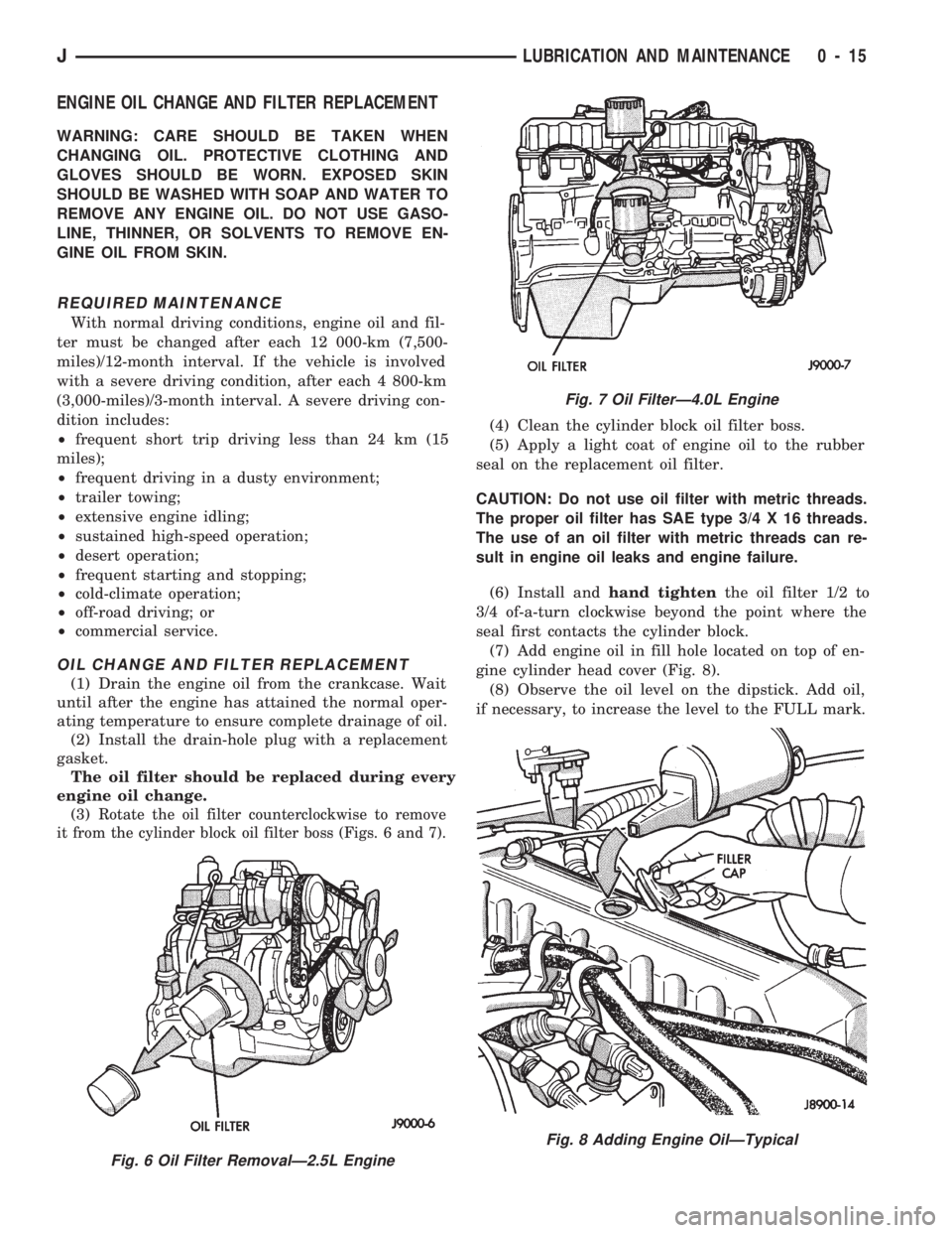
(3)
Rotate the oil filter counterclockwise to remove
it from the cylinder block oil filter boss (Figs. 6 and 7).
(4) Clean the cylinder block oil filter boss.
(5) Apply a light coat of engine oil to the rubber
seal on the replacement oil filter.
CAUTION: Do not use oil filter with metric threads.
The proper oil filter has SAE type 3/4 X 16 threads.
The use of an oil filter with metric threads can re-
sult in engine oil leaks and engine failure.
(6) Install andhand tightenthe oil filter 1/2 to
3/4 of-a-turn clockwise beyond the point where the
seal first contacts the cylinder block.
(7) Add engine oil in fill hole located on top of en-
gine cylinder head cover (Fig. 8).
(8) Observe the oil level on the dipstick. Add oil,
if necessary, to increase the level to the FULL mark.
Fig. 6 Oil Filter RemovalÐ2.5L Engine
Fig. 7 Oil FilterÐ4.0L Engine
Fig. 8 Adding Engine OilÐTypical
JLUBRICATION AND MAINTENANCE 0 - 15
Page 26 of 1784

DRAINING ATF/FILTER REMOVAL
Drain the automatic transmission fluid (ATF) im-
mediately after stopping the engine (before the ATF
cools).
(1) Raise and support the vehicle.
(2) Loosen the transmission pan bolts and drain
the original ATF into an appropriate container. Re-
move the pan bolts, the pan and the gasket.
Care should be exercised when disposing used
ATF after it has been drained from a vehicle
transmission.
(3) Remove the screws and the ATF filter (Fig. 8).
Discard the filter.
FILTER INSTALLATION/ATF RE-FILL
(1) Install a replacement ATF filter. Tighten the
screws with 4 NIm (35 in. lbs.) torque.
(2) Clean the pan thoroughly. Install a replace-
ment gasket on the pan. Install the pan with the at-
taching bolts:
²model AW-4 transmission Ð tighten the pan bolts
with 7 NIm (60 in. lbs.) torque; and
²model 998 transmission Ð tighten the pan bolts
with 17 NIm (150 in. lbs.) torque.
(3) Remove the support and lower the vehicle.
(4) Pour approximately 4.7 liters (5 quarts) of ATF
into the filler tube. Use MerconŸ ATF for AW-4 au-
tomatic transmissions. Use MOPAR ATF PLUS type
7176 or equivalent, for 998 automatic transmissions.
(5) Place a block in front of and at the rear of one
wheel/tire to prevent vehicle movement.
(6) Start the engine and allow it to idle a few min-
utes.
(7) Apply the brake pedal and engage the parking
brake. Move the transmission selector lever through
all positions, then place the selector lever in NEU-
TRAL position.(8) With the transmission at normal operating
temperature, observe the ATF level on the dipstick.
Add ATF (if necessary) to raise the level to the
FULL mark on the dipstick.Only 0.5 liter (1.0 pint)
will raise the level from the ADD mark to the
FULL mark when the ATF is at normal operat-
ing temperature.
(9) Inspect for fluid leaks and correct as necessary.
(10) Remove the wheel/tire blocks.
TRANSFER CASE
RECOMMENDED MAINTENANCE
The fluid (ATF) level in transfer cases should be
determined at the same time as the engine oil is
changed and the oil filter is replaced. Add ATF as
necessary.
In addition, transfer case ATF should be changed
after each 48 000-km (30,000-miles) interval of vehi-
cle operation has elapsed.
FLUID SPECIFICATIONS
If it is necessary to add fluid to a transfer case (or
when the fluid is changed), use MOPAR ATF PLUS
type 7176 or an equivalent MerconŸ/Dexron IIŸ
ATF.
FLUID LEVEL
The transfer case fill-hole plug is located at the
rear of the housing (Fig. 9).
Determine the transfer case fluid (ATF) level ac-
cording to the following procedure.
(1) Raise and support the vehicle.
(2) Remove the fill-hole plug from the transfer
case. The ATF level should be at the bottom edge of
the fill hole. The level can be slightly below the bot-
tom edge of the fill hole if the fluid is cold.
Fig. 9 Transfer CaseÐTypical
Fig. 8 ATF FilterÐTypical
JLUBRICATION AND MAINTENANCE 0 - 25
Page 32 of 1784

FRONT WHEEL BEARINGS
Only 2WD XJ vehicles are equipped with front
wheel bearings. XJ vehicles have semi-floating axle
shafts and axle shaft bearings that are lubricated via
differential lube oil.
RECOMMENDED MAINTENANCEÐ2WD XJ
VEHICLES
The front wheel bearings should be lubricated (re-
packed) at the same time as front brake pad/caliper
service is conducted.
LUBRICANT SPECIFICATION
Wheel bearings should be lubricated with a lubri-
cant that is identified as NLGI GC-LB lubricant.
INSPECTION/LUBRICATION
(1) Remove the wheel/tire and the disc brake cali-
per.Do not disconnect the caliper brake fluid
hose unless the caliper must also be removed for
maintenance. Support the caliper with a hanger
to prevent brake fluid hose damage.
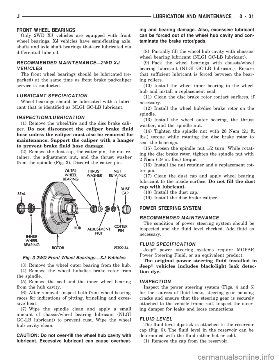
(2) Remove the dust cap, the cotter pin, the nut re-
tainer, the adjustment nut, and the thrust washer
from the spindle (Fig. 3). Discard the cotter pin.
(3) Remove the wheel outer bearing from the hub.
(4) Remove the wheel hub/disc brake rotor from
the spindle.
(5) Remove the seal and the inner wheel bearing
from the hub cavity.
(6) After removal, inspect both front wheel bearing
races for indications of pitting, brinelling and exces-
sive heat.
(7) Wipe the spindle clean and apply a small
amount of chassis/wheel bearing lubricant (NLGI
GC-LB lubricant) to prevent rust. Wipe the wheel
hub cavity clean.
CAUTION: Do not over-fill the wheel hub cavity with
lubricant. Excessive lubricant can cause overheat-ing and bearing damage. Also, excessive lubricant
can be forced out of the wheel hub cavity and con-
taminate the brake rotor/pads.
(8) Partially fill the wheel hub cavity with chassis/
wheel bearing lubricant (NLGI GC-LB lubricant).
(9) Pack the wheel bearings with chassis/wheel
bearing lubricant (NLGI GC-LB lubricant). Ensure
that sufficient lubricant is forced between the bear-
ing rollers.
(10) Install the wheel inner bearing in the wheel
hub and install a replacement seal.
(11) Clean the disc brake rotor contact surfaces, if
necessary.
(12) Install the wheel hub/disc brake rotor on the
spindle.
(13) Install the wheel outer bearing, the thrust
washer, and the spindle nut.
(14) Tighten the spindle nut with 28 NIm (21 ft.
lbs.) torque while rotating the disc brake rotor to
seat the bearings.
(15) Loosen the spindle nut 1/2 turn. While rotat-
ing the disc brake rotor, tighten the spindle nut with
2NIm (19 in. lbs.) torque.
(16) Install the nut retainer and a replacement cot-
ter pin.
(17) Clean the dust cap and apply wheel bearing
lubricant to the inside surface.Do not fill the dust
cap with lubricant.
(18) Install the dust cap.
(19) Install the disc brake caliper.
POWER STEERING SYSTEM
RECOMMENDED MAINTENANCE
The condition of power steering system should be
inspected and the fluid level checked. Add fluid as
necessary.
FLUID SPECIFICATION
Jeeptpower steering systems require MOPAR
Power Steering Fluid, or an equivalent product.
The original power steering fluid installed in
Jeeptvehicles includes black-light leak detec-
tion dye.
INSPECTION
Inspect the power steering system (Figs. 4 and 5)
for the sources of fluid leaks, steering gear housing
cracks and ensure that the steering gear is securely
attached to the vehicle frame rail. Inspect the steer-
ing damper for leaks and loose connections.
FLUID LEVEL
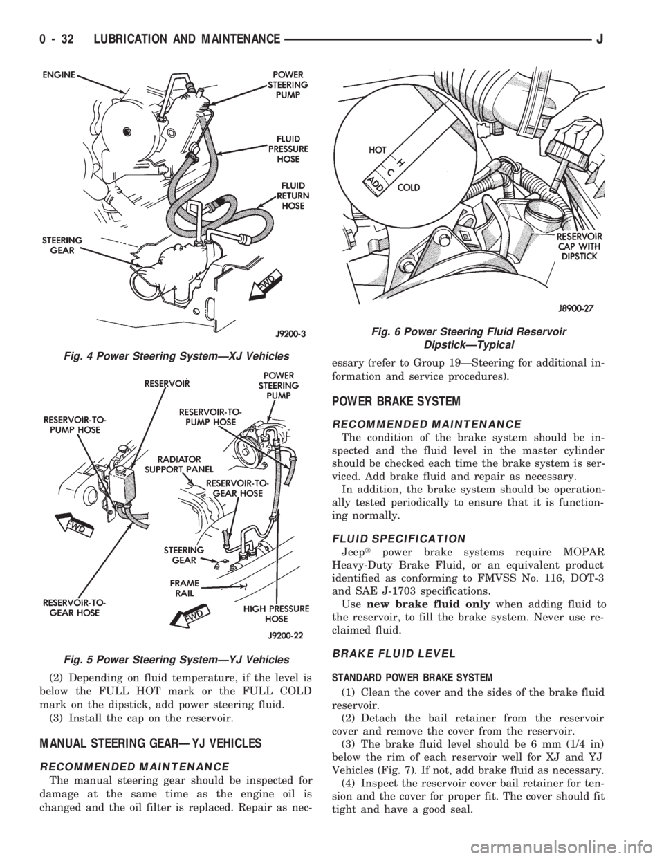
The fluid level dipstick is attached to the reservoir
cap (Fig. 6). The fluid level in the reservoir can be
determined with the fluid either hot or cold.
(1) Remove the cap from the reservoir.
Fig. 3 2WD Front Wheel BearingsÐXJ Vehicles
JLUBRICATION AND MAINTENANCE 0 - 31
Page 33 of 1784

(2) Depending on fluid temperature, if the level is
below the FULL HOT mark or the FULL COLD
mark on the dipstick, add power steering fluid.
(3) Install the cap on the reservoir.
MANUAL STEERING GEARÐYJ VEHICLES
RECOMMENDED MAINTENANCE
The manual steering gear should be inspected for
damage at the same time as the engine oil is
changed and the oil filter is replaced. Repair as nec-essary (refer to Group 19ÐSteering for additional in-
formation and service procedures).
POWER BRAKE SYSTEM
RECOMMENDED MAINTENANCE
The condition of the brake system should be in-
spected and the fluid level in the master cylinder
should be checked each time the brake system is ser-
viced. Add brake fluid and repair as necessary.
In addition, the brake system should be operation-
ally tested periodically to ensure that it is function-
ing normally.
FLUID SPECIFICATION
Jeeptpower brake systems require MOPAR
Heavy-Duty Brake Fluid, or an equivalent product
identified as conforming to FMVSS No. 116, DOT-3
and SAE J-1703 specifications.
Usenew brake fluid onlywhen adding fluid to
the reservoir, to fill the brake system. Never use re-
claimed fluid.
BRAKE FLUID LEVEL
STANDARD POWER BRAKE SYSTEM
(1) Clean the cover and the sides of the brake fluid
reservoir.
(2) Detach the bail retainer from the reservoir
cover and remove the cover from the reservoir.
(3) The brake fluid level should be 6 mm (1/4 in)
below the rim of each reservoir well for XJ and YJ
Vehicles (Fig. 7). If not, add brake fluid as necessary.
(4) Inspect the reservoir cover bail retainer for ten-
sion and the cover for proper fit. The cover should fit
tight and have a good seal.
Fig. 4 Power Steering SystemÐXJ Vehicles
Fig. 5 Power Steering SystemÐYJ Vehicles
Fig. 6 Power Steering Fluid Reservoir
DipstickÐTypical
0 - 32 LUBRICATION AND MAINTENANCEJ
Page 118 of 1784

(4) Inspect ignition coil connections. Verify that
coil secondary cable is firmly connected to coil (Figs.
5or6).(5) Verify that distributor cap is correctly attached
to distributor. Be sure that spark plug cables are
firmly connected to the distributor cap and the spark
plugs in their correct firing order. Be sure that coil
cable is firmly connected to distributor cap and coil.
Be sure that camshaft position sensor wire connector
is firmly connected to harness connector (Figs. 7 or
8). Inspect spark plug condition. Refer to Group 8D,
Ignition System. Connect vehicle to an oscilloscope
and inspect spark events for fouled or damaged spark
plugs or cables.
(6) Verify that generator output wire, generator
connector and ground wire are firmly connected to
the generator (Fig. 9).
(7) Inspect the system ground connections at the
cylinder block behind the engine oil dipstick tube
(Fig. 10).
Fig. 4 PDCÐXJ Models
Fig. 5 Ignition CoilÐ2.5L Engine
Fig. 6 Ignition CoilÐ4.0L Engine
Fig. 7 Distributor and WiringÐ2.5L Engine
Fig. 8 Distributor and WiringÐ4.0L Engine
JFUEL SYSTEM 14 - 33
Page 252 of 1784

Leakage Test. Do this if it is certain that coolant is
being lost and no leaks can be detected.
²Drops Slowly: Shows a small leak or seepage is oc-
curring. Examine all connections for seepage or
slight leakage with a flashlight. Inspect the radiator,
hoses, gasket edges and heater. Seal any small leak
holes with a Sealer Lubricant or equivalent. Repair
leak holes and reinspect the system with pressure
applied.
²Drops Quickly: Shows that a serious leakage is oc-
curring. Examine the system for serious external
leakage. If no leaks are visible, inspect for internal
leakage. Large radiator leak holes should be repaired
by a reputable radiator repair shop.
INTERNAL LEAKAGE INSPECTION
Remove the oil pan drain plug and drain a small
amount of engine oil. Coolant, being heavier will
drain first, or operate engine to churn oil, then ex-
amine dipstick for water globules. Inspect the trans-
mission dipstick for water globules. Inspect the
transmission fluid cooler for leakage. Operate the en-
gine without the pressure cap on the radiator until
thermostat opens.
Attach a Pressure Tester to the filler neck. If pres-
sure builds up quickly, a leak exists as result of a
faulty cylinder head gasket or crack in the engine.
Repair as necessary.
WARNING: DO NOT ALLOW PRESSURE TO EX-
CEED 124 KPA (18 PSI). TURN THE ENGINE OFF.
TO RELEASE THE PRESSURE, ROCK THE TESTER
FROM SIDE TO SIDE. WHEN REMOVING THE
TESTER, DO NOT TURN THE TESTER MORE THAN
1/2 TURN IF THE SYSTEM IS UNDER PRESSURE.
If there is no immediate pressure increase, pump
the Pressure Tester until the indicated pressure is
within the system range. Vibration of the gauge
pointer indicates compression or combustion leakage
into the cooling system.WARNING: DO NOT DISCONNECT THE SPARK
PLUG WIRES WHILE THE ENGINE IS OPERATING.
CAUTION: Do not operate the engine with a spark
plug shorted for more than a minute. The catalytic
converter may be damaged.
Isolate the compression leak by shorting each
spark plug to the cylinder block. The gauge pointer
should stop or decrease vibration when spark plug
for leaking cylinder is shorted. This happens because
of the absence of combustion pressure.
COMBUSTION LEAKAGE TEST (WITHOUT
PRESSURE TESTER)
DO NOT WASTE reusable coolant. If the solution
is clean, drain the coolant into a clean container for
reuse.
WARNING: DO NOT REMOVE THE CYLINDER
BLOCK DRAIN PLUGS OR LOOSEN THE RADIATOR
DRAINCOCK WITH THE SYSTEM HOT AND UNDER
PRESSURE. SERIOUS BURNS FROM COOLANT
CAN OCCUR.
Drain sufficient coolant to allow for thermostat re-
moval. Refer to Thermostat Replacement. Disconnect
the water pump drive belt.
Disconnect the upper radiator hose from the ther-
mostat housing. Remove the housing and thermostat.
Install the thermostat housing.
Add coolant to the radiator to bring the level to
within 6.3 mm (1/4 in) of the top of the thermostat
housing.
CAUTION: Avoid overheating. Do not operate the
engine for an excessive period of time. Open the
draincock immediately after the test to eliminate
boil over of coolant.
Start the engine and accelerate rapidly three times
(to approximately 3000 rpm) while observing the
coolant. If internal engine combustion gases are leak-
ing into the cooling system, bubbles will appear in
the coolant. If bubbles do not appear, there is no in-
ternal combustion gas leakage.
COOLANT RESERVE/OVERFLOW SYSTEM
The system works along with the radiator pressure
cap. This is done by using thermal expansion and
contraction of the coolant to keep the coolant free of
trapped air. It provides:
²A volume for coolant expansion and contraction.
²A convenient and safe method for checking/adjust-
ing coolant level at atmospheric pressure. This is
done without removing the radiator pressure cap.
²Some reserve coolant to cover minor leaks and
evaporation or boiling losses.
Fig. 20 Pressurizing SystemÐTypical
JCOOLING SYSTEM 7 - 19
Page 885 of 1784

(6) Apply Loctite 515, or equivalent on the rear
bearing cap (Fig. 6). The bead should be 3 mm (0.125
in) thick. DO NOT apply Loctite 515, or equivalent
to the lip of the seal.
(7) Install the rear main bearing cap. DO NOT
strike the cap more than twice for proper engage-
ment.
(8) Tighten the bolts of caps 1, 3, 4 and 5 to 54
Nzm (40 ft. lbs.) torque. Now tighten these bolts to 95
Nzm (70 ft. lbs.) torque. Finally, tighten these bolts
to 108 Nzm (80 ft. lbs.) torque.
(9) Push the crankshaft forward and backward.
Load the crankshaft front or rear and tighten cap
bolt No.2 to 54 Nzm (40 ft. lbs.) torque. Then tighten
to 95 Nzm (70 ft. lbs.) torque and finally tighten to
108 Nzm (80 ft. lbs.) torque.
(10) Rotate the crankshaft after tightening each
main bearing cap to ensure the crankshaft rotates
freely.
(11) Check crankshaft end play. Crankshaft end
play is controlled by the thrust bearing which is
flange and installed at the No.2 main bearing posi-
tion.
(a) Attach a magnetic base dial indicator to the
cylinder block at either the front or rear of the en-
gine.
(b) Position the dial indicator rod so that it is
parallel to the center line of the crankshaft.
(c) Pry the crankshaft forward, position the dial
indicator to zero.
(d) Pry the crankshaft forward and backward.
Note the dial indicator readings. End play is the
difference between the high and low measurements
(Fig. 7). Correct end play is 0.038-0.165 mm(0.0015-0.0065 inch). The desired specifications are
0.051-0.064 mm (0.002-0.0025 inch).
(e) If end play is not within specification, inspect
crankshaft thrust faces for wear. If no wear is ap-
parent, replace the thrust bearing and measure end
play. If end play is still not within specification, re-
place the crankshaft.
If the crankshaft was removed, install the crank-
shaft into the cylinder block (refer to Cylinder Block -
Assemble).
(12) Install the oil pan.
(13) Install the drain plug. Tighten the plug to 34
Nzm (25 ft. lbs.) torque.
(14) Lower the vehicle.
(15) Install the spark plugs. Tighten the plugs to
37 Nzm (27 ft. lbs.) torque.
(16) Fill the oil pan with engine oil to the full
mark on the dipstick level.
(17) Connect negative cable to battery.
REAR MAIN OIL SEALS
REMOVAL
(1) Remove the flywheel or converter drive plate.
Discard the old bolts.
(2) Pry out the seal from around the crankshaft
flange (Fig. 8).
INSTALLATION
(1) Coat the outer lip of the replacement rear main
bearing seal with engine oil.
(2) Carefully position the seal into place. Use rear
main Seal Installer Tool 6271 to install the seal flush
with the cylinder block.
CAUTION: The felt lip must be located inside the
flywheel mounting surface. If the lip is not posi-
tioned correctly the flywheel could tear the seal.
Fig. 6 Location of Loctite 515 (or equivalent)
Fig. 7 Crankshaft End Play Measurement
9 - 44 2.5L ENGINEJ