1994 JEEP CHEROKEE oil pressure
[x] Cancel search: oil pressurePage 3 of 1784
ROUTINE SERVICE
The following routine vehicle service is highly rec-
ommended on a monthly basis.
TIRESÐInspect the tires for unusual wear/damage
and determine if the inflation pressure is acceptable
for the vehicle load.
BATTERYÐInspect and clean the terminals.
Tighten the terminals, if necessary.
FLUIDSÐDetermine if the coolant, brake fluid,
power steering, automatic transmission, and clutch
fluid level are acceptable. Add fluid, if necessary.
LIGHTS/ELECTRICALÐTest all the electrically
operated systems in the vehicle for proper operation.
It is also recommended that the engine oil level
and the windshield washer fluid level be deter-
mined (and corrected) during each fuel fill-up.
FUEL REQUIREMENTS
All Jeeptengines require the use of unleaded gas-
oline. In addition, the fuel must have a minimum oc-
tane rating of 87.
CAUTION: UNLEADED FUEL ONLY must be used in
vehicles equipped with a catalyst emission control
system. All vehicles have reminders printed on the
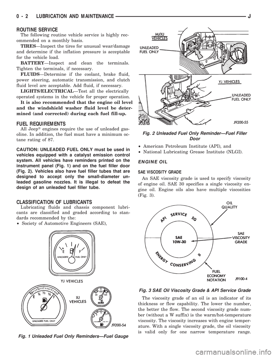
instrument panel (Fig. 1) and on the fuel filler door
(Fig. 2). Vehicles also have fuel filler tubes that are
designed to accept only the small-diameter un-
leaded gasoline nozzles. It is illegal to defeat the
design of an unleaded fuel filler tube.
CLASSIFICATION OF LUBRICANTS
Lubricating fluids and chassis component lubri-
cants are classified and graded according to stan-
dards recommended by the:
²Society of Automotive Engineers (SAE),²American Petroleum Institute (API), and
²National Lubricating Grease Institute (NLGI).
ENGINE OIL
SAE VISCOSITY GRADE
An SAE viscosity grade is used to specify viscosity
of engine oil. SAE 30 specifies a single viscosity en-
gine oil. Engine oils also have multiple viscosities
(Fig. 3).
The viscosity grade of an oil is an indicator of its
thickness or flow capability. The lower the number,
the better the flow. The second viscosity grade num-
ber (without a W suffix) is the warm/hot-temperature
viscosity. The viscosity increases with engine temper-
ature. With a single viscosity grade, the oil viscosity
is valid only for one narrow temperature range.
Fig. 1 Unleaded Fuel Only RemindersÐFuel Gauge
Fig. 2 Unleaded Fuel Only ReminderÐFuel Filler
Door
Fig. 3 SAE Oil Viscosity Grade & API Service Grade
0 - 2 LUBRICATION AND MAINTENANCEJ
Page 6 of 1784

MAINTENANCE SCHEDULES
INTRODUCTION
Chrysler Corporation has compiled recommended
lubrication and maintenance schedules and proce-
dures to help reduce premature wear or failure over
a broad range of operating conditions.
SEVERE SERVICE MAINTENANCE
If the vehicle is involved with a severe driving con-
dition, after each 4 800-km (3,000-miles)/3-month in-
terval. A severe driving condition includes:
²frequent short trip driving less than 24 km (15
miles);
²frequent driving in a dusty environment;
²trailer towing;
²extensive engine idling;
²sustained high-speed operation;
²desert operation;
²frequent starting and stopping;
²cold-climate operation;
²off-road driving; or
²commercial service.
MAINTENANCE SCHEDULES
AT EACH STOP FOR FUEL
²Check engine oil level, add as required.
²
Check windshield washer solvent and add if required.
ONCE A MONTH
²Check tire pressure and look for unusual wear or
damage.
²Inspect battery and clean and tighten terminals as
required.
²Check electrolyte level and add water as needed.
²Check fluid levels of coolant reservoir, power steer-
ing and transmission and add as needed.
²Check all lights and all other electrical items for
correct operation.
²Check rubber seals on each side of the radiator for
proper fit.
7,500 MILES (12 000 KM) OR AT 6 MONTHS
²Check engine coolant level, hoses and clamps.
²Change engine oil.
²Replace engine oil filter.
²Check exhaust system.
²Lubricate steering linkage (4x4 models).
²Lubricate propeller shaft universal joints.
²Rotate Tires.
15,000 MILES (24 000 KM) OR AT 12 MONTHS
²Check engine coolant level, hoses and clamps.
²Change engine oil.
²Replace engine oil filter.
²Check exhaust system.
²Lubricate steering linkage (4x4 models).
²Lubricate propeller shaft universal joints.²Check fluid level in battery.
²Rotate Tires.
22,500 MILES (36 000 KM) OR AT 18 MONTHS
²Check engine coolant level, hoses and clamps.
²Change engine oil.
²Replace engine oil filter.
²Check exhaust system.
²Lubricate steering linkage (4x4 models).
²Lubricate propeller shaft universal joints.
²Rotate Tires.
30,000 MILES (48 000 KM) OR AT 24 MONTHS
²Replace air cleaner filter.
²Replace spark plugs.
²Adjust drive belt.
²Check engine coolant level, hoses and clamps.
²Change engine oil.
²Replace engine oil filter.
²Check exhaust system.
²Lubricate steering linkage (4x4 models).
²Lubricate propeller shaft universal joints.
²Check fluid level in battery.
²Drain and refill automatic transmission.
²Drain and refill transfer case.
²Rotate Tires.
37,500 MILES (60 000 KM) OR AT 30 MONTHS
²Check engine coolant level, hoses and clamps.
²Change engine oil.
²Replace engine oil filter.
²Check exhaust system.
²Lubricate steering linkage (4x4 models).
²Lubricate propeller shaft universal joints.
²Drain and refill manual transmission.
²Rotate Tires.
45,000 MILES (72 500 KM) OR AT 36 MONTHS
²Check engine coolant level, hoses and clamps.
²Change engine oil.
²Replace engine oil filter.
²Check exhaust system.
²Lubricate steering linkage (4x4 models).
²Lubricate propeller shaft universal joints.
²Check fluid level in battery.
²Rotate Tires.
52,500 MILES (84 500 KM) OR AT 42 MONTHS
²Flush and replace engine coolant.
²Check engine coolant system hoses and clamps.
²Change engine oil.
²Replace engine oil filter.
²Check exhaust system.
²Lubricate steering linkage (4x4 models).
²Lubricate propeller shaft universal joints.
²Rotate Tires.
JLUBRICATION AND MAINTENANCE 0 - 5
Page 15 of 1784
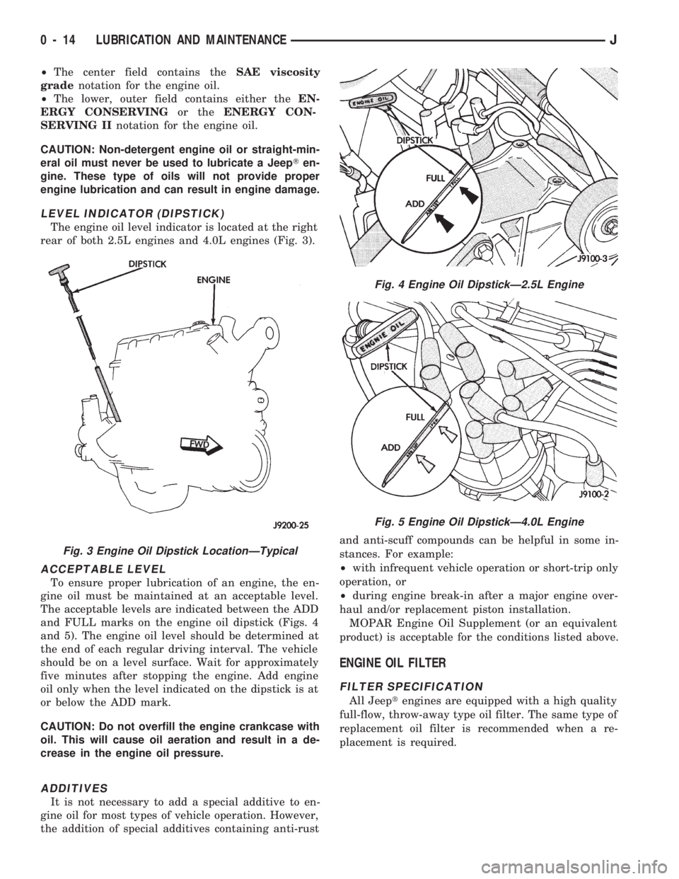
²The center field contains theSAE viscosity
gradenotation for the engine oil.
²The lower, outer field contains either theEN-
ERGY CONSERVINGor theENERGY CON-
SERVING IInotation for the engine oil.
CAUTION: Non-detergent engine oil or straight-min-
eral oil must never be used to lubricate a JeepTen-
gine. These type of oils will not provide proper
engine lubrication and can result in engine damage.
LEVEL INDICATOR (DIPSTICK)
The engine oil level indicator is located at the right
rear of both 2.5L engines and 4.0L engines (Fig. 3).
ACCEPTABLE LEVEL
To ensure proper lubrication of an engine, the en-
gine oil must be maintained at an acceptable level.
The acceptable levels are indicated between the ADD
and FULL marks on the engine oil dipstick (Figs. 4
and 5). The engine oil level should be determined at
the end of each regular driving interval. The vehicle
should be on a level surface. Wait for approximately
five minutes after stopping the engine. Add engine
oil only when the level indicated on the dipstick is at
or below the ADD mark.
CAUTION: Do not overfill the engine crankcase with
oil. This will cause oil aeration and result in a de-
crease in the engine oil pressure.
ADDITIVES
It is not necessary to add a special additive to en-
gine oil for most types of vehicle operation. However,
the addition of special additives containing anti-rustand anti-scuff compounds can be helpful in some in-
stances. For example:
²with infrequent vehicle operation or short-trip only
operation, or
²during engine break-in after a major engine over-
haul and/or replacement piston installation.
MOPAR Engine Oil Supplement (or an equivalent
product) is acceptable for the conditions listed above.
ENGINE OIL FILTER
FILTER SPECIFICATION
All Jeeptengines are equipped with a high quality
full-flow, throw-away type oil filter. The same type of
replacement oil filter is recommended when a re-
placement is required.
Fig. 3 Engine Oil Dipstick LocationÐTypical
Fig. 4 Engine Oil DipstickÐ2.5L Engine
Fig. 5 Engine Oil DipstickÐ4.0L Engine
0 - 14 LUBRICATION AND MAINTENANCEJ
Page 17 of 1784
CAUTION: Do not overfill the engine crankcase with
oil. This will cause oil aeration and result in a de-
crease in the engine oil pressure.
(9) Start the engine and observe the oil pressure
gauge or warning lamp. If the pressure does not in-
crease or the warning lamp does not go out, stop the
engine and determine the cause of the problem.
USED ENGINE OIL DISPOSAL
Care should be exercised when disposing used en-
gine oil after it has been drained from a vehicle en-
gine. Refer to the WARNING listed above.
COOLING SYSTEM
WARNING: USE EXTREME CAUTION WHEN RE-
MOVING THE RADIATOR CAP IF THE ENGINE IS
OPERATING. DO NOT PUT YOUR HANDS NEAR
THE DRIVE BELT(S), PULLEYS OR FAN BLADE. DO
NOT STAND IN A DIRECT LINE WITH THE FAN
BLADE.
RECOMMENDED MAINTENANCE
The engine coolant level should be determined at
least once a month and more often during periods of
hot weather. Add coolant as necessary.
COOLANT LEVEL
With the engine at normal operating temperature,
observe the coolant level in thecoolant recovery bot-
tle. The coolant level must be at least above the ADD
mark and preferably at the FULL mark. Add coolant
to the coolant recovery bottleonly, if necessary.
REQUIRED MAINTENANCE
Check coolant level, and inspect condition of cool-
ing system hoses and clamps after each 12 000-km
(7,500-miles).
Initially, coolant must be drained and cooling sys-
tem flushed and filled after the first 36 months of op-
eration. Thereafter, after each 24-months interval of
vehicle operation.
RECOMMENDED MAINTENANCE
The engine cooling system should be inspected for
proper operation and for component failure at least
every 12 months.
WARNING: IF THE ENGINE HAS BEEN RECENTLY
OPERATED, USE EXTREME CARE WHEN REMOV-
ING THE RADIATOR CAP TO AVOID SCALDING
WITH HOT, PRESSURIZED COOLANT.
For additional information, refer to Section 7, Cool-
ing System.COOLANT FREEZE PROTECTION
Jeeptcooling systems contain a 50/50 mixture of
anti-freeze and distilled water coolant. This is the
recommended coolant mixture for most ambient tem-
peratures. The factory-installed anti-freeze is formu-
lated to prevent corrosion on all cooling system metal
surfaces.
The degree of coolant freeze protection should be
tested every 12 months. If the coolant is contami-
nated orrustyin appearance, cooling system should
be drained and filled with a 50/50 mixture of fresh
coolant. For additional information, refer to Group
7ÐCooling System.
ENGINE AIR CLEANER FILTER ELEMENT
RECOMMENDED MAINTENANCE
Engine performance and fuel economy can be af-
fected by a restricted air cleaner filter. The filter
should be inspected on a regular basis for excessive
air restriction.
If the filter element is saturated with oil, replace
the filter element.
REQUIRED MAINTENANCE
Engine air cleaner filter must be replaced after
each 48 000-km (30,000-miles).
If a vehicle is frequently operated in dusty
areas, the air cleaner filter should be inspected
often.
FILTER ELEMENT SERVICE/REPLACEMENT
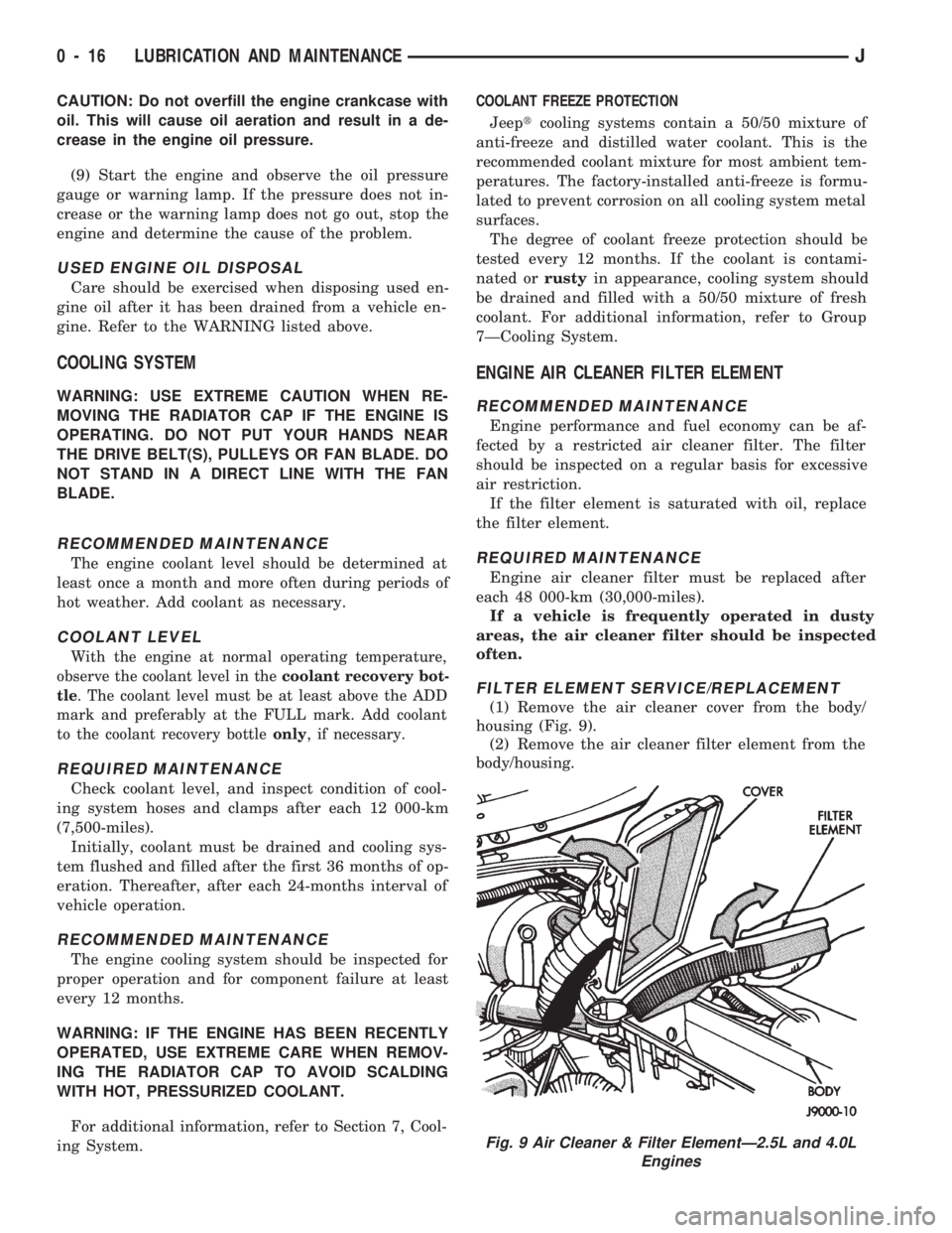
(1) Remove the air cleaner cover from the body/
housing (Fig. 9).
(2) Remove the air cleaner filter element from the
body/housing.
Fig. 9 Air Cleaner & Filter ElementÐ2.5L and 4.0L
Engines
0 - 16 LUBRICATION AND MAINTENANCEJ
Page 29 of 1784
CAUTION: It is very important that drive shafts be
lubricated at periodic intervals and that the speci-
fied type of lubricant be used. Failure to properly
lubricate could result in premature wear of drive
shaft components.
LUBRICATION FITTINGS
The drive shaft universal-joint couplers (U-joints)
and the front drive shaft slip yoke splines are
equipped with Zerk fittings. The (CV-joints) are lu-
bricated when assembled during manufacture and do
not require additional lubrication.
LUBRICANT SPECIFICATION
Drive shaft U-joint couplers and slip yoke splines
should be lubricated with a lubricant that is identi-
fied as NLGI GC-LB lubricant.
SLIP-YOKE SPLINE LUBRICATION
The method below will ensure complete lubrication
of the front drive shaft slip-yoke splines (Fig. 14).
(1) Clean the tips of the Zerk type fittings.
(2) Use a gun or another appropriate lubricant dis-
penser to force pressurized lubricant into the slip
yoke Zerk fittings.
(3) When the lubricant appears, cover the pressure
relief hole with a finger. Force pressurized lubricant
into fitting until it appears at slip-yoke seal.
RUBBER AND PLASTIC HOSES/TUBING
RECOMMENDED MAINTENANCE
The condition of underbody rubber hose and plastic
tubing should be inspected for failure at the same
time as oil is changed and oil filter is replaced.
HOSE/TUBING INSPECTION
Vehicle operating conditions determine the useable
life of underbody hoses and tubing. These conditions
include:²the extent and quality of vehicle maintenance,
²the geographic area of vehicle operation, and
²the length of exposure time to excess heat and
chemical contaminants.
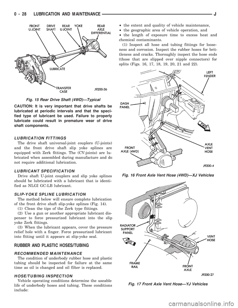
(1) Inspect all hose and tubing fittings for loose-
ness and corrosion. Inspect the rubber hoses for brit-
tleness and cracks. Thoroughly inspect the hose ends
(those that are slipped over nipple connectors) for
splits (Figs. 16, 17, 18, 19, 20, 21 and 22).
Fig. 16 Front Axle Vent Hose (4WD)ÐXJ Vehicles
Fig. 17 Front Axle Vent HoseÐYJ Vehicles
Fig. 15 Rear Drive Shaft (4WD)ÐTypical
0 - 28 LUBRICATION AND MAINTENANCEJ
Page 35 of 1784
(6) Inspect the disc brake caliper dust boot for cor-
rect installation, damage/tears and indications of
brake fluid leakage. Inspect the bushings and pins
for corrosion, tears and a binding condition.
(7) Pull the rear wheel cylinder dust boot back to
expose the wheel cylinder housing and inspect for
fluid leaks. Inspect the pistons and cylinder bores for
proper appearance.
(8) Inspect the brake differential warning valve
and housing for indications of leakage, kinked hoses
and loose fittings.
PARK BRAKE
(1) As applicable, engage the park brake lever or
pedal and then release it.
(2) If the park brake is functioning normally, test
it for smooth operation and vehicle-holding capabil-
ity.
(3) Inspect the park brake cables for kinks, fraying
and a binding condition.
(4) With the park brake released, the rear wheels
should rotate without restriction. Adjust the park
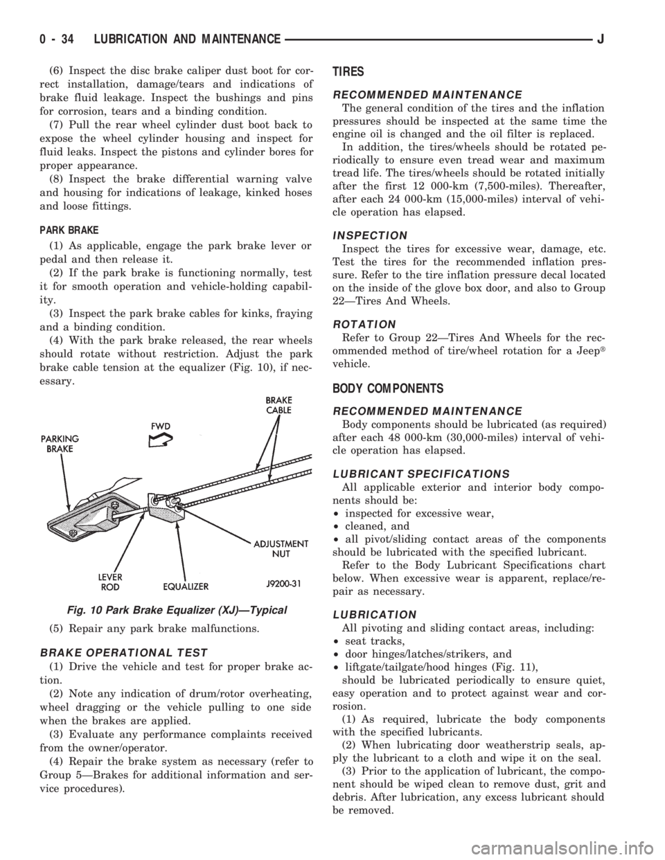
brake cable tension at the equalizer (Fig. 10), if nec-
essary.
(5) Repair any park brake malfunctions.
BRAKE OPERATIONAL TEST
(1) Drive the vehicle and test for proper brake ac-
tion.
(2) Note any indication of drum/rotor overheating,
wheel dragging or the vehicle pulling to one side
when the brakes are applied.
(3) Evaluate any performance complaints received
from the owner/operator.
(4) Repair the brake system as necessary (refer to
Group 5ÐBrakes for additional information and ser-
vice procedures).
TIRES
RECOMMENDED MAINTENANCE
The general condition of the tires and the inflation
pressures should be inspected at the same time the
engine oil is changed and the oil filter is replaced.
In addition, the tires/wheels should be rotated pe-
riodically to ensure even tread wear and maximum
tread life. The tires/wheels should be rotated initially
after the first 12 000-km (7,500-miles). Thereafter,
after each 24 000-km (15,000-miles) interval of vehi-
cle operation has elapsed.
INSPECTION
Inspect the tires for excessive wear, damage, etc.
Test the tires for the recommended inflation pres-
sure. Refer to the tire inflation pressure decal located
on the inside of the glove box door, and also to Group
22ÐTires And Wheels.
ROTATION
Refer to Group 22ÐTires And Wheels for the rec-
ommended method of tire/wheel rotation for a Jeept
vehicle.
BODY COMPONENTS
RECOMMENDED MAINTENANCE
Body components should be lubricated (as required)
after each 48 000-km (30,000-miles) interval of vehi-
cle operation has elapsed.
LUBRICANT SPECIFICATIONS
All applicable exterior and interior body compo-
nents should be:
²inspected for excessive wear,
²cleaned, and
²all pivot/sliding contact areas of the components
should be lubricated with the specified lubricant.
Refer to the Body Lubricant Specifications chart
below. When excessive wear is apparent, replace/re-
pair as necessary.
LUBRICATION
All pivoting and sliding contact areas, including:
²seat tracks,
²door hinges/latches/strikers, and
²liftgate/tailgate/hood hinges (Fig. 11),
should be lubricated periodically to ensure quiet,
easy operation and to protect against wear and cor-
rosion.
(1) As required, lubricate the body components
with the specified lubricants.
(2) When lubricating door weatherstrip seals, ap-
ply the lubricant to a cloth and wipe it on the seal.
(3) Prior to the application of lubricant, the compo-
nent should be wiped clean to remove dust, grit and
debris. After lubrication, any excess lubricant should
be removed.
Fig. 10 Park Brake Equalizer (XJ)ÐTypical
0 - 34 LUBRICATION AND MAINTENANCEJ
Page 57 of 1784
MODEL 30 AXLE AND TUBE AXLE (2WD)
INDEX
page page
Axle Bushing Replacement................. 32
Axle Shaft Ð Cardan U-Joint................ 25
Axle Specifications....................... 46
Backlash and Contact Pattern Analysis........ 44
Cleaning/Inspection....................... 35
Differential and Pinion Measurement.......... 38
Differential Assembly...................... 36
Differential Disassembly.................... 34
Differential Installation..................... 43
Differential Removal...................... 32
Differential Shim Pack Measurement and Adjustment.42
Drive Axle Assembly ReplacementÐXJ Vehicles . 21
Drive Axle Assembly ReplacementÐYJ Vehicles . 21Final Assembly.......................... 44
Hub Bearing and Axle Shaft................ 24
Information............................. 20
Inner Axle Shaft Oil Seal Replacement........ 33
Lubricant Change........................ 22
Lubricant Specifications.................... 20
Pinion Gear Assembly/Installation............ 40
Pinion Gear Depth Information.............. 37
Pinion Removal/Disassembly................ 34
Pinion Seal Replacement.................. 23
Steering Knuckle and Ball Studs............. 30
Vacuum Disconnect Axle Ð YJ Vehicles....... 26
INFORMATION
The housing for Model 30 front axles consists of an
iron center casting (differential housing) with axle
shaft tubes extending from either side. The tubes are
pressed into and welded to the differential housing to
form a one-piece axle housing.
The integral type housing, hypoid gear design has
the centerline of the pinion set above the centerline
of the ring gear.
The axle has a fitting for a vent hose used to re-
lieve internal pressure caused by lubricant vaporiza-
tion and internal expansion.
The axles are equipped with semi-floating axle
shafts, meaning that loads are supported by the hub
bearings. The axle shafts are retained by nuts at the
hub bearings. The hub bearings are bolted to the
steering knuckle at the outboard end of the axle tube
yoke. The hub bearings are serviced as an assembly.
The axles are equipped with ABS brake sensors.
The sensors are attached to the knuckle assemblies
and tone rings are pressed on the axle shaft.Use
care when removing axle shafts as NOT to dam-
age the tone wheel or the sensor.
The stamped steel cover provides a means for in-
spection and servicing the differential.
The Model 30 axle has the assembly part number
and gear ratio listed on a tag. The tag is attached to
the housing cover. Build date identification codes are
stamped on the axle shaft tube cover side.
The differential case is a one-piece design. The dif-
ferential pinion mate shaft is retained with a roll
pin. Differential bearing preload and ring gear back-
lash is adjusted by the use of shims (select thick-
ness). The shims are located between the differential
bearing cones and case. Pinion bearing preload is set
and maintained by the use of collapsible spacer.
PINION GEAR DEPTH MEASUREMENT WITH
PINION GAUGE SET 6774, Pinion Block 6733 and
Dial Indicator C-3339 is performed when;²Axle/differential housing is being replaced
²Original pinion depth shim pack is lost or mis-
placed
²Replacing the differential case
²Original differential bearing shim pack is lost or
misplaced
COMMAND-TRACÐYJ VEHICLES
The Command-Trac system is a vacuum disconnect
axle. The system has a two-piece axle shaft coupled
together by a shift collar. For two-wheel drive oper-
ation, the vacuum motor and shift fork disengages
the axle shaft splines. For four-wheel drive opera-
tion, the vacuum motor and shift fork engages the
splines.
SELEC-TRACÐXJ VEHICLES
The Selec-Trac system is a non-disconnect axle.
Shifting from two-wheel to four-wheel drive is at the
transfer case.
For XJ vehicles equipped withSelec-Tracand
ABS brake system, refer to Group 5ÐBrakes for ad-
ditional service information.
LUBRICANT SPECIFICATIONS
Multi-purpose, hypoid gear lubricant should be
used for Model 30 axles. The lubricant should have
MIL-L-2105C and API GL 5 quality specifications.
MOPARtHypoid Gear Lubricant conforms to both of
these specifications.
²The factory fill for the Model 30 axle is SAE 75W
gear lubricant.Do not use heavier weight lubri-
cant, this will cause axle engagement difficulties.
²The factory installed lubricant quantity for the
NON-DISCONNECT TYPE AXLE is 5061 fluid oz..
²The factory installed lubricant quantity for the
VACUUM-DISCONNECT TYPE AXLE is 5661 fluid
oz..
2 - 20 FRONT SUSPENSION AND AXLEJ
Page 62 of 1784
INSTALLATION
(1) Thoroughly clean the axle shaft (Fig. 6) and ap-
ply a thin film of Mopar Wheel Bearing Grease to
the shaft splines, seal contact surface, hub bore.
(2) Install the axle shaft into the housing and dif-
ferential side gears. Avoid damaging the axle shaft
oil seals in the differential.
(3) Install the hub bearing and brake dust shield
to the knuckle.
(4) Install the hub to knuckle bolts and tighten to
102 Nzm (75 ft. lbs.) torque.
(5) Install the hub washer and nut. Tighten the
hub nut to 237 Nzm (175 ft. lbs.) torque. Install the
nut retainer and a new cotter pin (Fig. 6).
(6) Install the brake components, refer to Group 5,
Brakes.
(7) Install the wheel and tire assembly.
(8) Remove support and lower the vehicle.
AXLE SHAFTÐ CARDAN U-JOINT
DISASSEMBLY
Single cardan U-joints are not serviceable. If defec-
tive, they must be replaced as a unit. If the bearings,
seals, spider or bearing caps are damaged or worn,
replace the complete U-joint.
CAUTION: Clamp only the forged portion of the
yoke in the vise. Also, to avoid distorting the yoke,
do not over tighten the vise jaws.
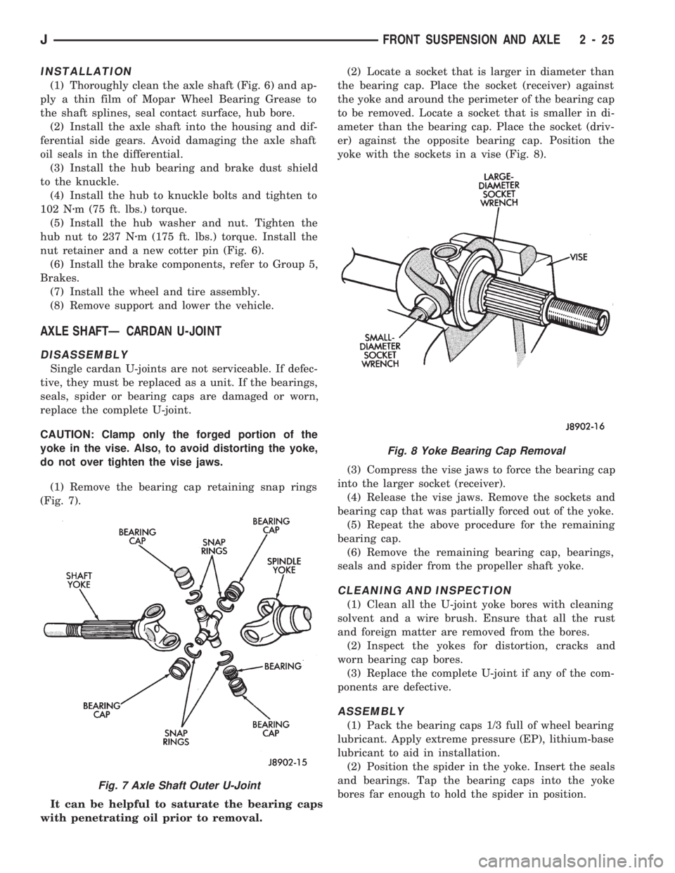
(1) Remove the bearing cap retaining snap rings
(Fig. 7).
It can be helpful to saturate the bearing caps
with penetrating oil prior to removal.(2) Locate a socket that is larger in diameter than
the bearing cap. Place the socket (receiver) against
the yoke and around the perimeter of the bearing cap
to be removed. Locate a socket that is smaller in di-
ameter than the bearing cap. Place the socket (driv-
er) against the opposite bearing cap. Position the
yoke with the sockets in a vise (Fig. 8).
(3) Compress the vise jaws to force the bearing cap
into the larger socket (receiver).
(4) Release the vise jaws. Remove the sockets and
bearing cap that was partially forced out of the yoke.
(5) Repeat the above procedure for the remaining
bearing cap.
(6) Remove the remaining bearing cap, bearings,
seals and spider from the propeller shaft yoke.
CLEANING AND INSPECTION
(1) Clean all the U-joint yoke bores with cleaning
solvent and a wire brush. Ensure that all the rust
and foreign matter are removed from the bores.
(2) Inspect the yokes for distortion, cracks and
worn bearing cap bores.
(3) Replace the complete U-joint if any of the com-
ponents are defective.
ASSEMBLY
(1) Pack the bearing caps 1/3 full of wheel bearing
lubricant. Apply extreme pressure (EP), lithium-base
lubricant to aid in installation.
(2) Position the spider in the yoke. Insert the seals
and bearings. Tap the bearing caps into the yoke
bores far enough to hold the spider in position.
Fig. 7 Axle Shaft Outer U-Joint
Fig. 8 Yoke Bearing Cap Removal
JFRONT SUSPENSION AND AXLE 2 - 25