1994 JEEP CHEROKEE battery replacement
[x] Cancel search: battery replacementPage 14 of 1784

ENGINE MAINTENANCE
INDEX
page page
Accessory Drive Belt...................... 20
Air-Conditioner Compressor/Hoses/Fittings...... 21
Battery................................ 18
Cooling System.......................... 16
Crankcase Ventilation System............... 17
Engine Air Cleaner Filter Element............ 16
Engine Break-In......................... 13
Engine Oil.............................. 13Engine Oil Change and Filter Replacement..... 15
Engine Oil Filter......................... 14
Engine Supports......................... 20
Exhaust System......................... 20
Fuel Usage StatementÐGas Engines......... 17
Ignition Cables, Distributor Cap and Rotor...... 18
Rubber and Plastic Ducts/Hoses/Tubing....... 19
Spark Plugs............................ 18
ENGINE BREAK-IN
After first starting a new engine, allow it to idle
and warm up for at least 15 seconds before shifting
the transmission into a drive gear.
Drive the vehicle at:
²varying speeds less than 80 km/h (50 mph) for the
first 160 km (100 miles), and
²speeds less than 88 km/h (55 mph) for the first 800
km (500 miles).
Avoid driving at full-throttle for extended periods
of time. Also, avoid fast acceleration and sudden
stops.
A special break-in engine oil is not required. The
original oil installed in a vehicle is a quality lubri-
cant. There is no requirement to have the oil
changed or the oil filter replaced until the first
scheduled maintenance interval.
The engine oil, coolant and all the other engine re-
lated fluid levels should be determined on a regular
basis.
ENGINE OIL
SPECIFICATIONS
API SERVICE GRADE
For maximum engine protection during all driving
conditions, install an engine oil that conforms to API
Service Grade. MOPAR Engine Oil conforms to all of
these API Service Grades.
SAE VISCOSITY
SAE designated multi-viscosity grade engine oil is
to protect engines. This type of engine oil can usually
be installed and remain in the engine until the next
scheduled oil change. Select the engine oil viscosity
according to the lowest ambient air temperature ex-
pected before the next scheduled oil change (Fig.1).
Low viscosity engine oil allows easier engine starting
during cold weather. SAE 5W-30 viscosity engine oil
is recommended when the ambient air temperatures
consistently decrease to below 10ÉF (-12ÉC).ENERGY CONSERVING OIL
In selecting the correct API grade and SAE grade,
anENERGY CONSERVINGtype engine oil is also
recommended.
CONTAINER IDENTIFICATION
Standard engine oil notations have been adopted
for selection of engine oil. The notations are located
on side of plastic bottles and on the top of engine oil
cans (Fig. 2).
²The top, outer field contains theAPI Service
Gradenotation for the engine oil.
Fig. 1 Temperature/Engine Oil Viscosity
Fig. 2 Engine Oil Container Standard Notations
JLUBRICATION AND MAINTENANCE 0 - 13
Page 200 of 1784
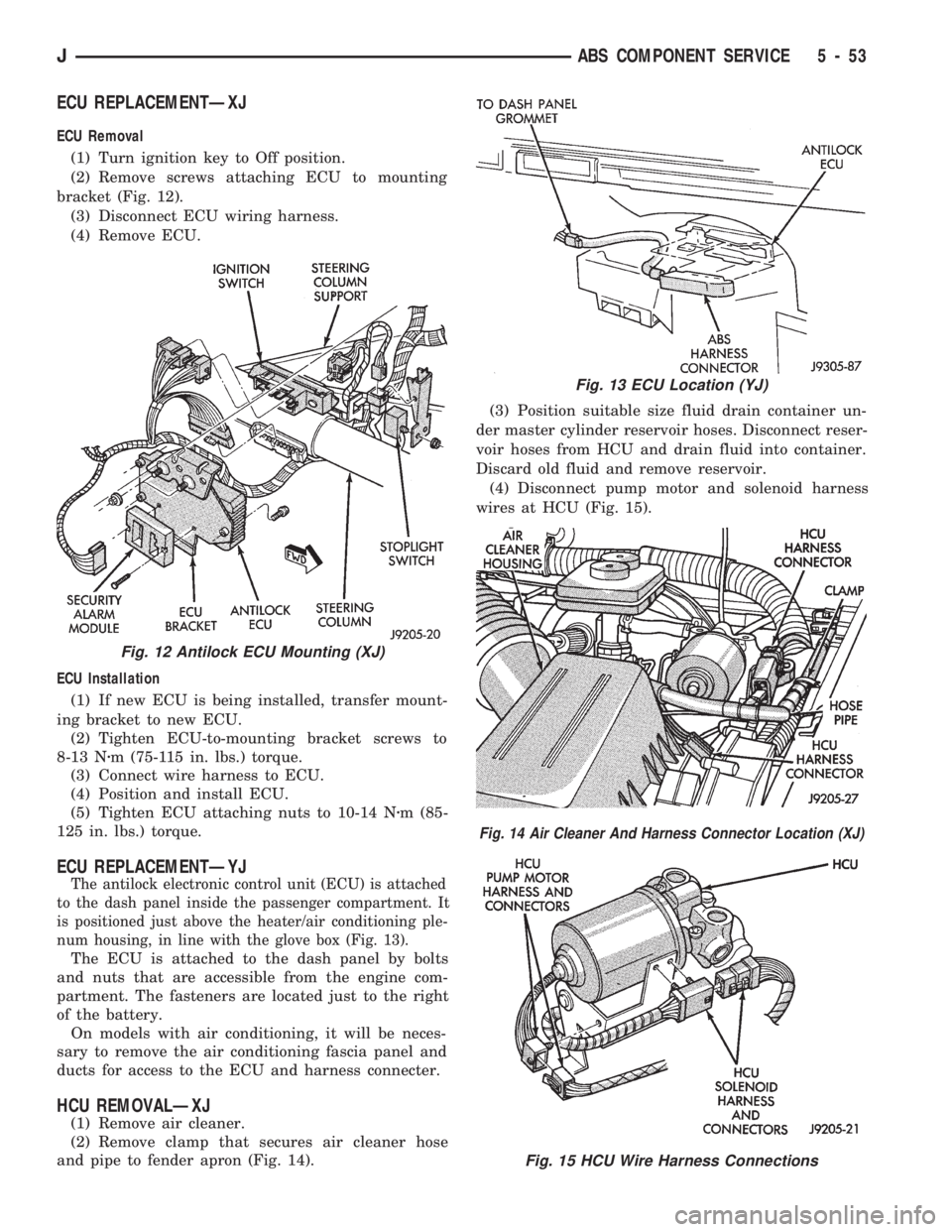
ECU REPLACEMENTÐXJ
ECU Removal
(1) Turn ignition key to Off position.
(2) Remove screws attaching ECU to mounting
bracket (Fig. 12).
(3) Disconnect ECU wiring harness.
(4) Remove ECU.
ECU Installation
(1) If new ECU is being installed, transfer mount-
ing bracket to new ECU.
(2) Tighten ECU-to-mounting bracket screws to
8-13 Nzm (75-115 in. lbs.) torque.
(3) Connect wire harness to ECU.
(4) Position and install ECU.
(5) Tighten ECU attaching nuts to 10-14 Nzm (85-
125 in. lbs.) torque.
ECU REPLACEMENTÐYJ
The antilock electronic control unit (ECU) is attached
to the dash panel inside the passenger compartment. It
is positioned just above the heater/air conditioning ple-
num housing, in line with the glove box (Fig. 13).
The ECU is attached to the dash panel by bolts
and nuts that are accessible from the engine com-
partment. The fasteners are located just to the right
of the battery.
On models with air conditioning, it will be neces-
sary to remove the air conditioning fascia panel and
ducts for access to the ECU and harness connecter.
HCU REMOVALÐXJ
(1) Remove air cleaner.
(2) Remove clamp that secures air cleaner hose
and pipe to fender apron (Fig. 14).(3) Position suitable size fluid drain container un-
der master cylinder reservoir hoses. Disconnect reser-
voir hoses from HCU and drain fluid into container.
Discard old fluid and remove reservoir.
(4) Disconnect pump motor and solenoid harness
wires at HCU (Fig. 15).
Fig. 12 Antilock ECU Mounting (XJ)
Fig. 13 ECU Location (YJ)
Fig. 14 Air Cleaner And Harness Connector Location (XJ)
Fig. 15 HCU Wire Harness Connections
JABS COMPONENT SERVICE 5 - 53
Page 255 of 1784
RADIATORS
GENERAL INFORMATION
All radiators are down flow types except XJ models
with 4.0L engines. Radiators in XJ models equipped
with the 4.0L six-cylinder engine, are the cross flow
type. Plastic tanks are used on all radiators.
CAUTION: Plastic tanks, while stronger than brass,
are subject to damage by impact, such as
wrenches.
If plastic tank has been damaged, plastic tank
and/or O-rings are available for service repair. Tank
replacement should be done by qualified personal
with proper equipment.
RADIATOR COOLANT FLOW CHECK
The following procedure will determine if coolant is
flowing through the cooling system.
If engine is cold, idle engine until normal operating
temperature is reached. Then feel the upper radiator
hose. If hose is hot, the thermostat is open and water
is circulating through cooling system.
RADIATOR REMOVAL/INSTALLATION
WARNING: DO NOT REMOVE THE CYLINDER
BLOCK DRAIN PLUGS, RADIATOR CAP, OR
LOOSEN THE RADIATOR DRAINCOCK WITH THE
SYSTEM HOT AND PRESSURIZED. SERIOUS
BURNS FROM THE COOLANT CAN OCCUR.
DO NOT WASTE reusable coolant. If solution is
clean, drain coolant into a clean container for reuse.
WARNING: CONSTANT TENSION HOSE CLAMPS
ARE USED ON MOST COOLING SYSTEM HOSES.
WHEN REMOVING OR INSTALLING, USE ONLY
TOOLS DESIGNED FOR SERVICING THIS TYPE OF
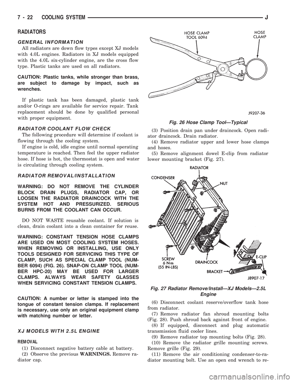
CLAMP, SUCH AS SPECIAL CLAMP TOOL (NUM-
BER 6094) (FIG. 26). SNAP-ON CLAMP TOOL (NUM-
BER HPC-20) MAY BE USED FOR LARGER
CLAMPS. ALWAYS WEAR SAFETY GLASSES
WHEN SERVICING CONSTANT TENSION CLAMPS.
CAUTION: A number or letter is stamped into the
tongue of constant tension clamps. If replacement
is necessary, use only an original equipment clamp
with matching number or letter.
XJ MODELS WITH 2.5L ENGINE
REMOVAL
(1) Disconnect negative battery cable at battery.
(2) Observe the previousWARNINGS.Remove ra-
diator cap.(3) Position drain pan under draincock. Open radi-
ator draincock. Drain radiator.
(4) Remove radiator upper and lower hose clamps
and hoses.
(5) Remove alignment dowel E-clip from radiator
lower mounting bracket (Fig. 27).
(6) Disconnect coolant reserve/overflow tank hose
from radiator.
(7) Remove radiator fan shroud mounting bolts
(Fig. 28). Push shroud back against front of engine.
(8) If equipped, disconnect and plug automatic
transmission fluid cooler lines.
(9) Remove radiator top mounting bolts (Fig. 28).
(10) Remove the radiator grille mounting screws.
Remove grille (Fig. 29).
(11) Remove the air conditioning condenser-to-ra-
diator mounting bolt. Use an open end wrench to re-
Fig. 26 Hose Clamp ToolÐTypical
Fig. 27 Radiator Remove/InstallÐXJ ModelsÐ2.5L
Engine
7 - 22 COOLING SYSTEMJ
Page 257 of 1784
WARNING: CONSTANT TENSION HOSE CLAMPS
ARE USED ON MOST COOLING SYSTEM HOSES.
WHEN REMOVING OR INSTALLING, USE ONLY
TOOLS DESIGNED FOR SERVICING THIS TYPE OF
CLAMP, SUCH AS SPECIAL CLAMP TOOL (NUM-
BER 6094) (FIG. 26). SNAP-ON CLAMP TOOL (NUM-
BER HPC-20) MAY BE USED FOR LARGER
CLAMPS. ALWAYS WEAR SAFETY GLASSES
WHEN SERVICING CONSTANT TENSION CLAMPS.
CAUTION: A number or letter is stamped into the
tongue of constant tension clamps. If replacement
is necessary, use only an original equipment clamp
with matching number or letter.
REMOVAL
(1) Disconnect negative battery cable at battery.
(2) Observe the previousWARNINGS.
(3) Remove pressure cap.
(4) For access to radiator draincock, remove radia-
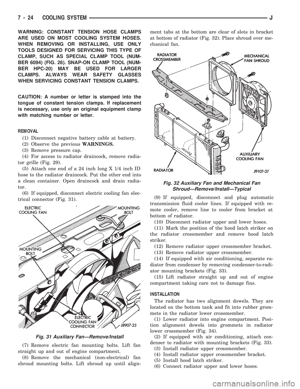
tor grille (Fig. 29).
(5) Attach one end of a 24 inch long X 1/4 inch ID
hose to the radiator draincock. Put the other end into
a clean container. Open draincock and drain radia-
tor.
(6) If equipped, disconnect electric cooling fan elec-
trical connector (Fig. 31).
(7) Remove electric fan mounting bolts. Lift fan
straight up and out of engine compartment.
(8) Remove the mechanical (non-electrical) fan
shroud mounting bolts. Lift shroud up until align-ment tabs at the bottom are clear of slots in bracket
at bottom of radiator (Fig. 32). Place shroud over me-
chanical fan.
(9) If equipped, disconnect and plug automatic
transmission fluid cooler lines. If equipped with re-
mote cooler, remove line to cooler from bracket at
bottom of radiator.
(10) Disconnect radiator upper and lower hoses.
(11) Mark the position of the hood latch striker on
the radiator crossmember and remove hood latch
striker.
(12) Remove radiator upper crossmember bracket.
(13) Remove radiator upper crossmember.
(14) If equipped with air conditioning, separate ra-
diator from condenser by removing condenser-to-radi-
ator mounting brackets (Fig. 33).
(15) Lift radiator straight up and out of engine
compartment taking care not to damage fins.
INSTALLATION
The radiator has two alignment dowels. They are
located on the bottom tank and fit into rubber grom-
mets in the radiator lower crossmember.
(1) Lower radiator into engine compartment. Posi-
tion alignment dowels into grommets in radiator
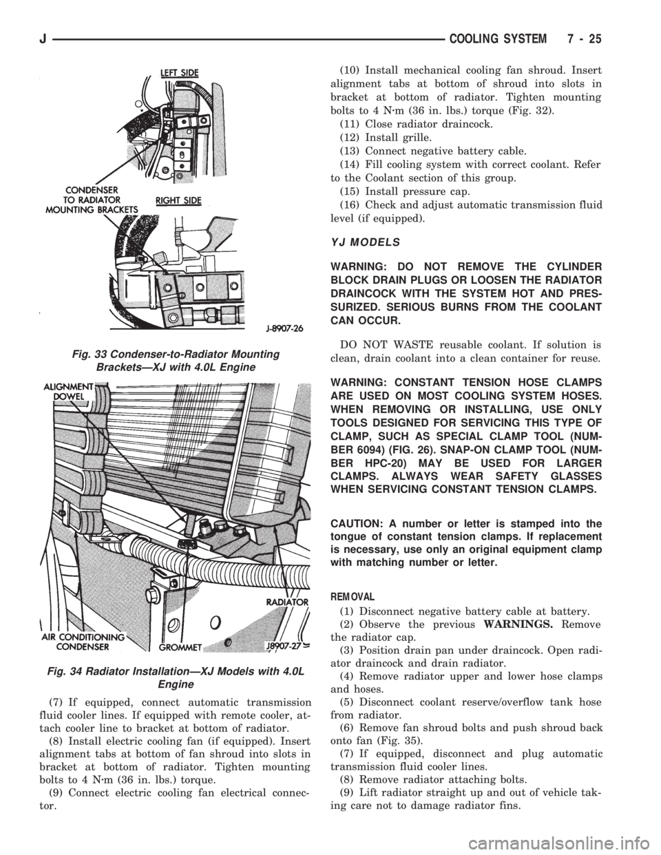
lower crossmember (Fig. 34).
(2) If equipped with air conditioning, attach con-
denser to radiator with mounting brackets (Fig. 33).
(3) Install radiator upper crossmember.
(4) Install radiator upper crossmember bracket.
(5) Install hood latch striker.
(6) Connect radiator upper and lower hoses.
Fig. 31 Auxiliary FanÐRemove/Install
Fig. 32 Auxiliary Fan and Mechanical Fan
ShroudÐRemove/InstallÐTypical
7 - 24 COOLING SYSTEMJ
Page 258 of 1784
(7) If equipped, connect automatic transmission
fluid cooler lines. If equipped with remote cooler, at-
tach cooler line to bracket at bottom of radiator.
(8) Install electric cooling fan (if equipped). Insert
alignment tabs at bottom of fan shroud into slots in
bracket at bottom of radiator. Tighten mounting
bolts to 4 Nzm (36 in. lbs.) torque.
(9) Connect electric cooling fan electrical connec-
tor.(10) Install mechanical cooling fan shroud. Insert
alignment tabs at bottom of shroud into slots in
bracket at bottom of radiator. Tighten mounting
bolts to 4 Nzm (36 in. lbs.) torque (Fig. 32).
(11) Close radiator draincock.
(12) Install grille.
(13) Connect negative battery cable.
(14) Fill cooling system with correct coolant. Refer
to the Coolant section of this group.
(15) Install pressure cap.
(16) Check and adjust automatic transmission fluid
level (if equipped).
YJ MODELS
WARNING: DO NOT REMOVE THE CYLINDER
BLOCK DRAIN PLUGS OR LOOSEN THE RADIATOR
DRAINCOCK WITH THE SYSTEM HOT AND PRES-
SURIZED. SERIOUS BURNS FROM THE COOLANT
CAN OCCUR.
DO NOT WASTE reusable coolant. If solution is
clean, drain coolant into a clean container for reuse.
WARNING: CONSTANT TENSION HOSE CLAMPS
ARE USED ON MOST COOLING SYSTEM HOSES.
WHEN REMOVING OR INSTALLING, USE ONLY
TOOLS DESIGNED FOR SERVICING THIS TYPE OF
CLAMP, SUCH AS SPECIAL CLAMP TOOL (NUM-
BER 6094) (FIG. 26). SNAP-ON CLAMP TOOL (NUM-
BER HPC-20) MAY BE USED FOR LARGER
CLAMPS. ALWAYS WEAR SAFETY GLASSES
WHEN SERVICING CONSTANT TENSION CLAMPS.
CAUTION: A number or letter is stamped into the
tongue of constant tension clamps. If replacement
is necessary, use only an original equipment clamp
with matching number or letter.
REMOVAL
(1) Disconnect negative battery cable at battery.
(2) Observe the previousWARNINGS.Remove
the radiator cap.
(3) Position drain pan under draincock. Open radi-
ator draincock and drain radiator.
(4) Remove radiator upper and lower hose clamps
and hoses.
(5) Disconnect coolant reserve/overflow tank hose
from radiator.
(6) Remove fan shroud bolts and push shroud back
onto fan (Fig. 35).
(7) If equipped, disconnect and plug automatic
transmission fluid cooler lines.
(8) Remove radiator attaching bolts.
(9) Lift radiator straight up and out of vehicle tak-
ing care not to damage radiator fins.
Fig. 33 Condenser-to-Radiator Mounting
BracketsÐXJ with 4.0L Engine
Fig. 34 Radiator InstallationÐXJ Models with 4.0L
Engine
JCOOLING SYSTEM 7 - 25
Page 259 of 1784
INSTALLATION
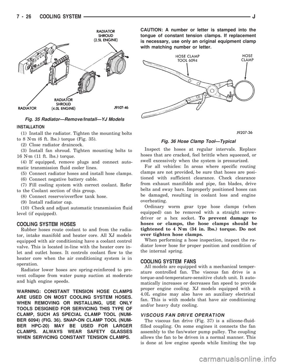
(1) Install the radiator. Tighten the mounting bolts
to8Nzm (6 ft. lbs.) torque (Fig. 35).
(2) Close radiator draincock.
(3) Install fan shroud. Tighten mounting bolts to
16 Nzm (11 ft. lbs.) torque.
(4) If equipped, remove plugs and connect auto-
matic transmission fluid cooler lines.
(5) Connect radiator hoses and install hose clamps.
(6) Connect negative battery cable.
(7) Fill cooling system with correct coolant. Refer
to the Coolant section of this group.
(8) Connect reserve/overflow tank hose.
(9) Install radiator cap.
(10) Check and adjust automatic transmission fluid
level (if equipped).
COOLING SYSTEM HOSES
Rubber hoses route coolant to and from the radia-
tor, intake manifold and heater core. All XJ models
equipped with air conditioning have a coolant control
valve. This is located in-line with the heater core in-
let and outlet hoses. It controls coolant flow to the
heater core when the air conditioning system is in
operation.
Radiator lower hoses are spring-reinforced to pre-
vent collapse from water pump suction at moderate
and high engine speeds.
WARNING: CONSTANT TENSION HOSE CLAMPS
ARE USED ON MOST COOLING SYSTEM HOSES.
WHEN REMOVING OR INSTALLING, USE ONLY
TOOLS DESIGNED FOR SERVICING THIS TYPE OF
CLAMP, SUCH AS SPECIAL CLAMP TOOL (NUM-
BER 6094) (FIG. 36). SNAP-ON CLAMP TOOL (NUM-
BER HPC-20) MAY BE USED FOR LARGER
CLAMPS. ALWAYS WEAR SAFETY GLASSES
WHEN SERVICING CONSTANT TENSION CLAMPS.CAUTION: A number or letter is stamped into the
tongue of constant tension clamps. If replacement
is necessary, use only an original equipment clamp
with matching number or letter.
Inspect the hoses at regular intervals. Replace
hoses that are cracked, feel brittle when squeezed, or
swell excessively when the system is pressurized.
For all vehicles: In areas where specific routing
clamps are not provided, be sure that hoses are posi-
tioned with sufficient clearance. Check clearance
from exhaust manifolds and pipe, fan blades, drive
belts and sway bars. Improperly positioned hoses can
be damaged, resulting in coolant loss and engine
overheating.
Ordinary worm gear type hose clamps (when
equipped) can be removed with a straight screw-
driver or a hex socket.To prevent damage to
hoses or clamps, the hose clamps should be
tightened to 4 Nzm (34 in. lbs.) torque. Do not
over tighten hose clamps.
When performing a hose inspection, inspect the ra-
diator lower hose for proper position and condition of
the internal spring.
COOLING SYSTEM FANS
All models are equipped with a mechanical temper-
ature controlled fan. The viscous fan drive is a
torque-and-temperature-sensitive clutch unit. It auto-
matically increases or decreases fan speed to provide
proper engine cooling. XJ models equipped with a
4.0L engine may also have an auxiliary electrical
fan. This is with models that have air conditioning
and/or heavy duty cooling.
VISCOUS FAN DRIVE OPERATION
The viscous fan drive (Fig. 37) is a silicone-fluid-
filled coupling. On some engines it connects the fan
assembly to the fan/water pump pulley. The coupling
allows the fan to be driven in a normal manner. This
is done at low engine speeds while limiting the top
Fig. 35 RadiatorÐRemove/InstallÐYJ Models
Fig. 36 Hose Clamp ToolÐTypical
7 - 26 COOLING SYSTEMJ
Page 294 of 1784
BATTERY/STARTER/GENERATOR SERVICE
CONTENTS
page page
BATTERY SERVICE PROCEDURES.......... 1
ENGINE STARTER MOTOR SERVICE
PROCEDURES......................... 4GENERATOR SERVICE PROCEDURES........ 7
SPECIFICATIONS....................... 10
BATTERY SERVICE PROCEDURES
GENERAL INFORMATION
This section covers battery removal and installa-
tion procedures only. For diagnostic procedures, refer
to Group 8A - Battery/Starting/Charging Systems Di-
agnostics.
BATTERY MAINTENANCE
(1) Inspect cable terminals for corrosion and dam-
age. Remove the corrosion using a wire brush, or
post and terminal cleaner, and a sodium bicarbonate/
water solution. Replace cables that have damaged or
deformed terminals.
Be sure filler caps or vents are installed when
washing battery to prevent solution from enter-
ing battery.
(2) Clean outside of battery case if the original
battery is to be installed. Clean top cover with di-
luted ammonia or a sodium bicarbonate/water solu-
tion to remove acid film. Flush with clean water.
Ensure that cleaning solution does not enter cells.
(3) Remove corrosion from the terminals with a
wire brush or post and terminal cleaner. Inspect the
case for cracks or other damage that would result in
leakage of electrolyte.
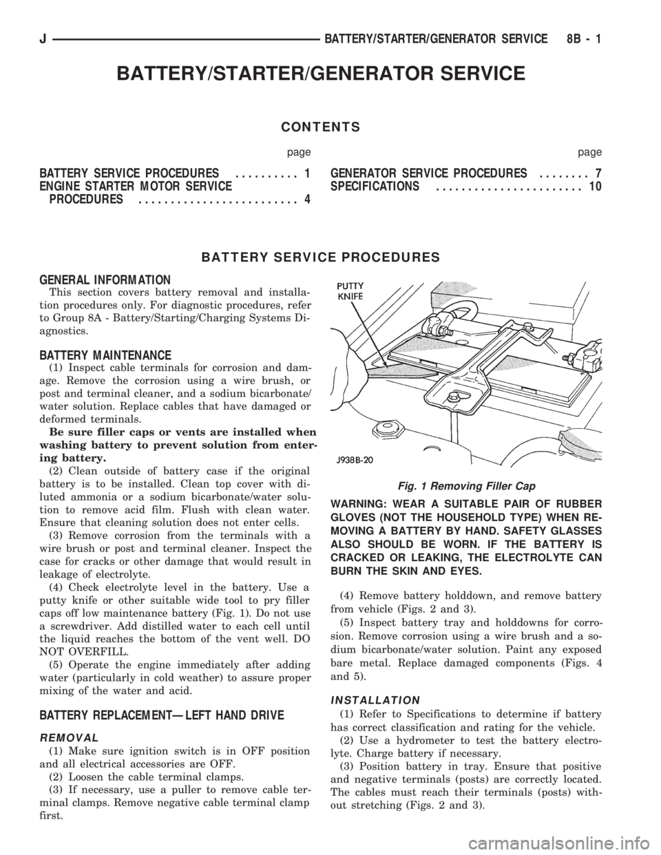
(4) Check electrolyte level in the battery. Use a
putty knife or other suitable wide tool to pry filler
caps off low maintenance battery (Fig. 1). Do not use
a screwdriver. Add distilled water to each cell until
the liquid reaches the bottom of the vent well. DO
NOT OVERFILL.
(5) Operate the engine immediately after adding
water (particularly in cold weather) to assure proper
mixing of the water and acid.
BATTERY REPLACEMENTÐLEFT HAND DRIVE
REMOVAL
(1) Make sure ignition switch is in OFF position
and all electrical accessories are OFF.
(2) Loosen the cable terminal clamps.
(3) If necessary, use a puller to remove cable ter-
minal clamps. Remove negative cable terminal clamp
first.WARNING: WEAR A SUITABLE PAIR OF RUBBER
GLOVES (NOT THE HOUSEHOLD TYPE) WHEN RE-
MOVING A BATTERY BY HAND. SAFETY GLASSES
ALSO SHOULD BE WORN. IF THE BATTERY IS
CRACKED OR LEAKING, THE ELECTROLYTE CAN
BURN THE SKIN AND EYES.
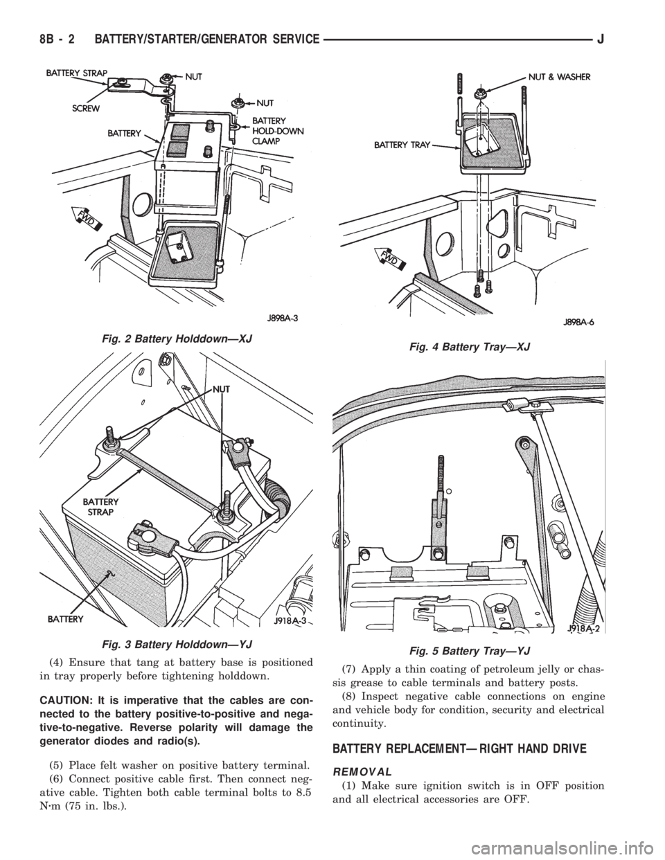
(4) Remove battery holddown, and remove battery
from vehicle (Figs. 2 and 3).
(5) Inspect battery tray and holddowns for corro-
sion. Remove corrosion using a wire brush and a so-
dium bicarbonate/water solution. Paint any exposed
bare metal. Replace damaged components (Figs. 4
and 5).
INSTALLATION
(1) Refer to Specifications to determine if battery
has correct classification and rating for the vehicle.
(2) Use a hydrometer to test the battery electro-
lyte. Charge battery if necessary.
(3) Position battery in tray. Ensure that positive
and negative terminals (posts) are correctly located.
The cables must reach their terminals (posts) with-
out stretching (Figs. 2 and 3).
Fig. 1 Removing Filler Cap
JBATTERY/STARTER/GENERATOR SERVICE 8B - 1
Page 295 of 1784
(4) Ensure that tang at battery base is positioned
in tray properly before tightening holddown.
CAUTION: It is imperative that the cables are con-
nected to the battery positive-to-positive and nega-
tive-to-negative. Reverse polarity will damage the
generator diodes and radio(s).
(5) Place felt washer on positive battery terminal.
(6) Connect positive cable first. Then connect neg-
ative cable. Tighten both cable terminal bolts to 8.5
Nzm (75 in. lbs.).(7) Apply a thin coating of petroleum jelly or chas-
sis grease to cable terminals and battery posts.
(8) Inspect negative cable connections on engine
and vehicle body for condition, security and electrical
continuity.
BATTERY REPLACEMENTÐRIGHT HAND DRIVE
REMOVAL
(1) Make sure ignition switch is in OFF position
and all electrical accessories are OFF.
Fig. 2 Battery HolddownÐXJ
Fig. 3 Battery HolddownÐYJ
Fig. 4 Battery TrayÐXJ
Fig. 5 Battery TrayÐYJ
8B - 2 BATTERY/STARTER/GENERATOR SERVICEJ