1994 JEEP CHEROKEE battery replacement
[x] Cancel search: battery replacementPage 297 of 1784

ENGINE STARTER MOTOR SERVICE PROCEDURES
INDEX
page page
2.5L Starter General Information.............. 4
2.5L Starter Motor Removal/Installation......... 5
4.0L Starter General Information.............. 6
4.0L Starter Motor Removal/Installation......... 6General Information........................ 4
Park/Neutral Position Switch................. 6
Starter Relay Replacement.................. 4
GENERAL INFORMATION
This section will cover the starting system compo-
nent service procedures only. For diagnostic proce-
dures, refer to Group 8A - Battery/Starting/Charging
Systems Diagnostics.
Starting system components: battery, starter mo-
tor, starter relay, starter solenoid, ignition switch,
connecting wires and battery cables. A park/neutral
position switch is used with automatic transmissions.
STARTER RELAY REPLACEMENT
The starter relay is located in the Power Distribu-
tion Center (Figs. 1 and 2). Refer to underside of
Power Distribution Center cover for relay location.
(1) Disconnect negative cable from battery.
(2) Replace relay.
(3) Connect negative cable to battery.
(4) Test relay operation.
2.5L STARTER GENERAL INFORMATION
The 2.5L engine starter motor incorporates several
features to create an efficient, lightweight unit.
A planetary gear system (intermediate transmis-
sion) between the electric motor and pinion shaftmakes it possible to reduce the dimensions of the
starter. This also makes it possible to obtain a higher
rotational speed to produce the same torque at the
pinion.
The permanent magnet field consists of six two-
component high strength magnets. The magnets are
aligned according to their polarity and are perma-
nently fixed in the starter frame.
The brush holder plate consists of a plastic base-
plate with four tubular brush holders.
This unit is highly sensitive to hammering, shocks
and external pressure.
CAUTION: The starter motor MUST NOT BE
CLAMPED in a vise by the starter frame. Doing so
may damage the magnets. It may be clamped by the
mounting flange ONLY.
CAUTION: Do not connect starter motor incorrectly
when tests are being performed. The magnets may
be damaged and rendered unserviceable.
²Ensure cleanliness when performing repairs.
Fig. 1 Power Distribution CenterÐXJ
Fig. 2 Power Distribution CenterÐYJ
8B - 4 BATTERY/STARTER/GENERATOR SERVICEJ
Page 300 of 1784
GENERATOR SERVICE PROCEDURES
GENERAL
The generator is belt-driven by the engine. All en-
gines use serpentine drive. This section will cover
generator removal and installation. The generator is
not serviceable. Information covering on-vehicle test-
ing can be found in Group 8A - Battery/Starting/
Charging Systems Diagnostics.
GENERATOR REPLACEMENTÐLEFT HAND DRIVE
WARNING: FAILURE TO DISCONNECT NEGATIVE
CABLE FROM BATTERY BEFORE DISCONNECTING
RED (OUTPUT) WIRE CONNECTOR FROM GENER-
ATOR CAN RESULT IN INJURY.
ALL YJ AND XJ WITH 2.5L ENGINE
Belt tension is adjusted at the power steering pump
(or idler pulley if not equipped with power steering).
To replace generator:
(1) Disconnect negative cable from battery.
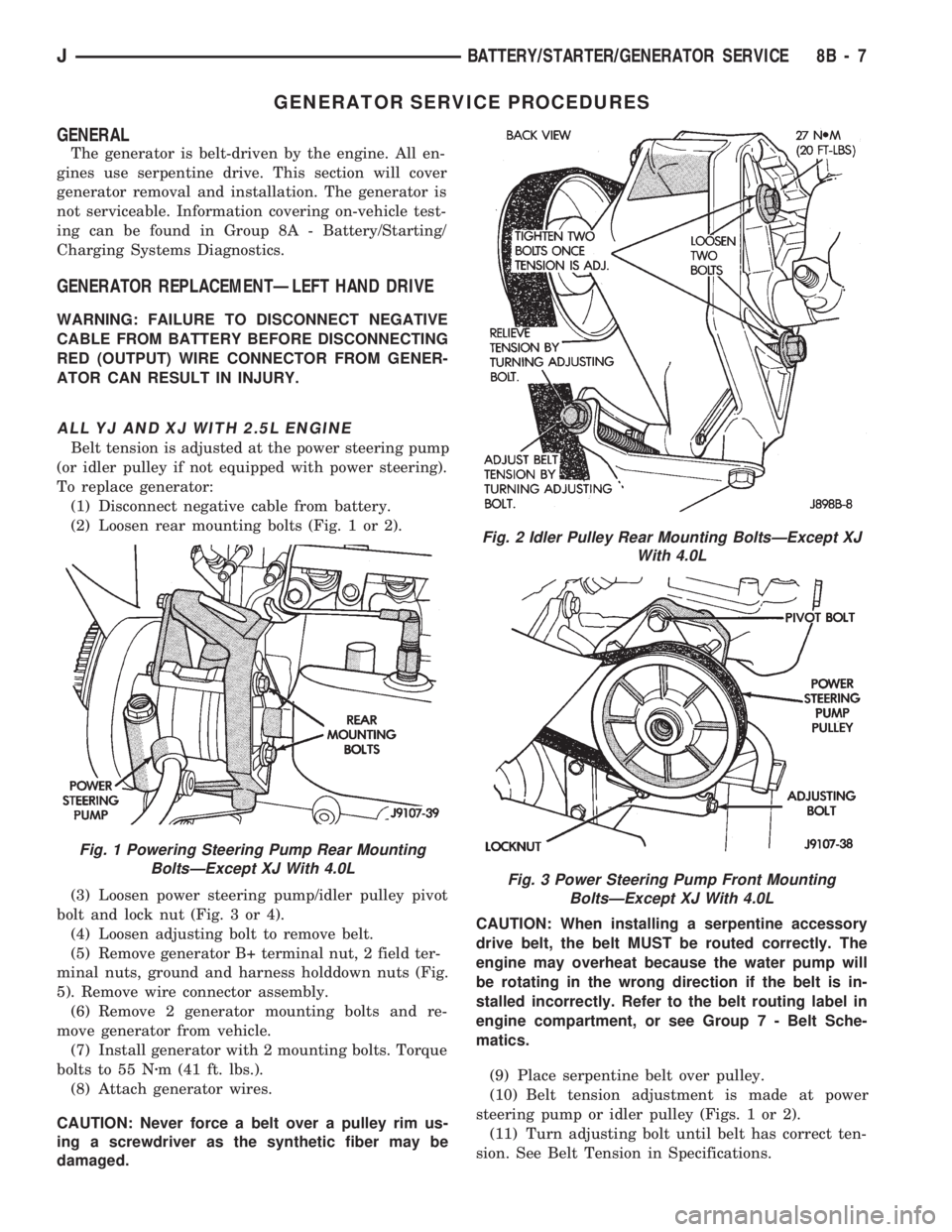
(2) Loosen rear mounting bolts (Fig. 1 or 2).
(3) Loosen power steering pump/idler pulley pivot
bolt and lock nut (Fig. 3 or 4).
(4) Loosen adjusting bolt to remove belt.
(5) Remove generator B+ terminal nut, 2 field ter-
minal nuts, ground and harness holddown nuts (Fig.
5). Remove wire connector assembly.
(6) Remove 2 generator mounting bolts and re-
move generator from vehicle.
(7) Install generator with 2 mounting bolts. Torque
bolts to 55 Nzm (41 ft. lbs.).
(8) Attach generator wires.
CAUTION: Never force a belt over a pulley rim us-
ing a screwdriver as the synthetic fiber may be
damaged.CAUTION: When installing a serpentine accessory
drive belt, the belt MUST be routed correctly. The
engine may overheat because the water pump will
be rotating in the wrong direction if the belt is in-
stalled incorrectly. Refer to the belt routing label in
engine compartment, or see Group 7 - Belt Sche-
matics.
(9) Place serpentine belt over pulley.
(10) Belt tension adjustment is made at power
steering pump or idler pulley (Figs. 1 or 2).
(11) Turn adjusting bolt until belt has correct ten-
sion. See Belt Tension in Specifications.
Fig. 1 Powering Steering Pump Rear Mounting
BoltsÐExcept XJ With 4.0L
Fig. 2 Idler Pulley Rear Mounting BoltsÐExcept XJ
With 4.0L
Fig. 3 Power Steering Pump Front Mounting
BoltsÐExcept XJ With 4.0L
JBATTERY/STARTER/GENERATOR SERVICE 8B - 7
Page 302 of 1784
CAUTION: Never force a belt over a pulley rim us-
ing a screwdriver as the synthetic fiber may be
damaged.
CAUTION: When installing a serpentine accessory
drive belt, the belt MUST be routed correctly. The
engine may overheat because the water pump will
be rotating in the wrong direction if the belt is in-
stalled incorrectly. Refer to the belt routing label in
engine compartment, or see Group 7 - Belt Sche-
matics.
(10) Place serpentine belt over pulley.
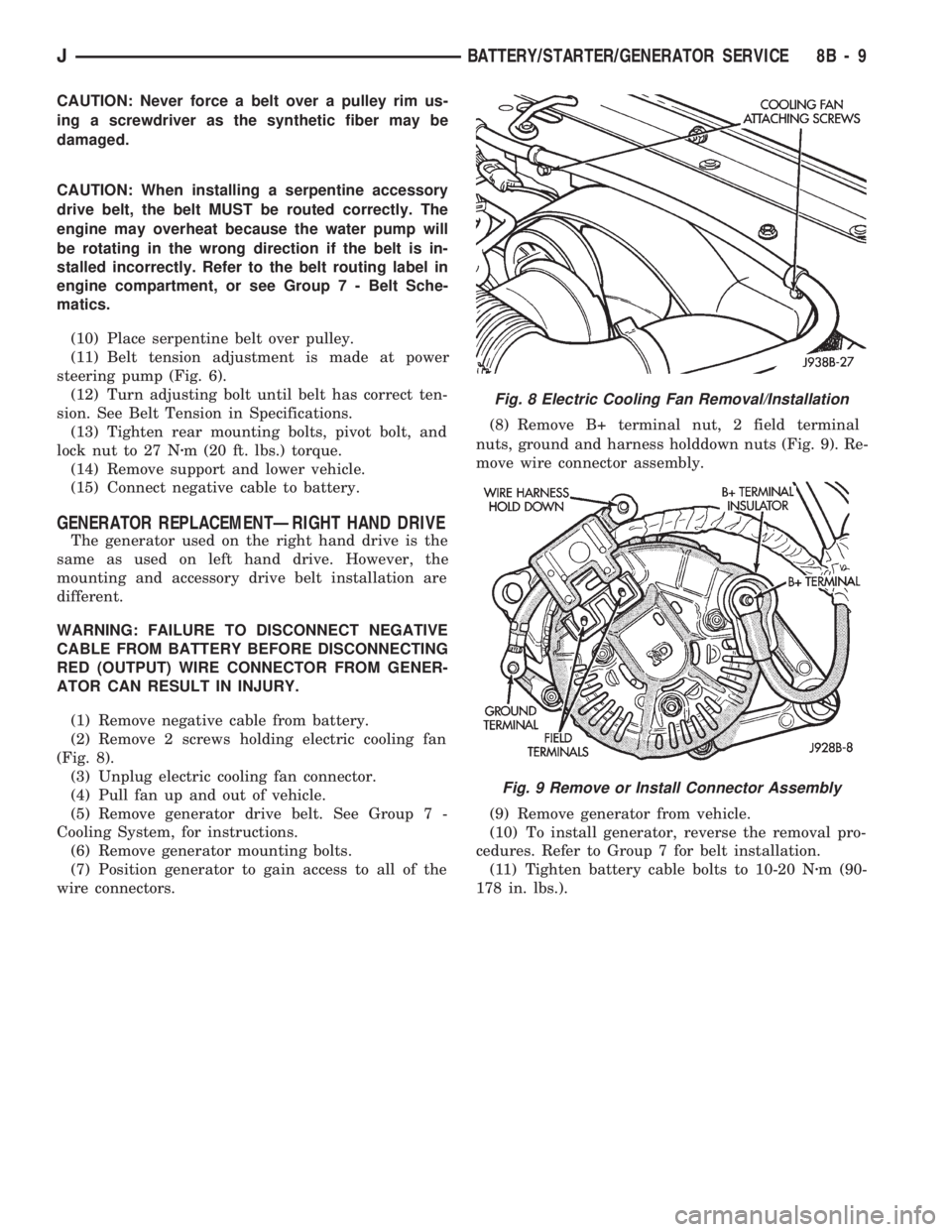
(11) Belt tension adjustment is made at power
steering pump (Fig. 6).
(12) Turn adjusting bolt until belt has correct ten-
sion. See Belt Tension in Specifications.
(13) Tighten rear mounting bolts, pivot bolt, and
lock nut to 27 Nzm (20 ft. lbs.) torque.
(14) Remove support and lower vehicle.
(15) Connect negative cable to battery.
GENERATOR REPLACEMENTÐRIGHT HAND DRIVE
The generator used on the right hand drive is the
same as used on left hand drive. However, the
mounting and accessory drive belt installation are
different.
WARNING: FAILURE TO DISCONNECT NEGATIVE
CABLE FROM BATTERY BEFORE DISCONNECTING
RED (OUTPUT) WIRE CONNECTOR FROM GENER-
ATOR CAN RESULT IN INJURY.
(1) Remove negative cable from battery.
(2) Remove 2 screws holding electric cooling fan
(Fig. 8).
(3) Unplug electric cooling fan connector.
(4) Pull fan up and out of vehicle.
(5) Remove generator drive belt. See Group 7 -
Cooling System, for instructions.
(6) Remove generator mounting bolts.
(7) Position generator to gain access to all of the
wire connectors.(8) Remove B+ terminal nut, 2 field terminal
nuts, ground and harness holddown nuts (Fig. 9). Re-
move wire connector assembly.
(9) Remove generator from vehicle.
(10) To install generator, reverse the removal pro-
cedures. Refer to Group 7 for belt installation.
(11) Tighten battery cable bolts to 10-20 Nzm (90-
178 in. lbs.).
Fig. 8 Electric Cooling Fan Removal/Installation
Fig. 9 Remove or Install Connector Assembly
JBATTERY/STARTER/GENERATOR SERVICE 8B - 9
Page 338 of 1784
The camshaft position sensor is located in the dis-
tributor on all engines (Fig. 9).
Refer to figure 9 for an exploded view of the dis-
tributor.
(1) Disconnect the negative battery cable at bat-
tery.
(2) On XJ models equipped with A/C, remove the
electrical cooling fan and shroud assembly from the
radiator. This will provide room to turn the engine
with a socket and ratchet using the vibration damper
bolt.
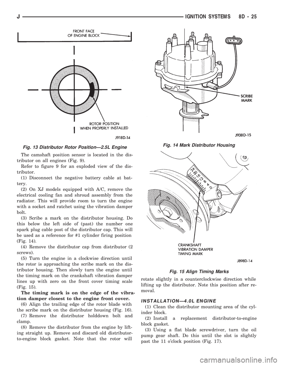
(3) Scribe a mark on the distributor housing. Do
this below the left side of (past) the number one
spark plug cable post of the distributor cap. This will
be used as a reference for #1 cylinder firing position
(Fig. 14).
(4) Remove the distributor cap from distributor (2
screws).
(5) Turn the engine in a clockwise direction until
the rotor is approaching the scribe mark on the dis-
tributor housing. Then slowly turn the engine until
the timing mark on the crankshaft vibration damper
lines up with zero on the front cover timing scale
(Fig. 15).
The timing mark is on the edge of the vibra-
tion damper closest to the engine front cover.
(6) Align the trailing edge of the rotor blade with
the scribe mark on the distributor housing (Fig. 16).
(7) Remove the distributor holddown bolt and
clamp.
(8) Remove the distributor from the engine by lift-
ing straight up. Remove and discard old distributor-
to-engine block gasket. Note that the rotor willrotate slightly in a counterclockwise direction while
lifting up the distributor. Note this position after re-
moval.
INSTALLATIONÐ4.0L ENGINE
(1) Clean the distributor mounting area of the cyl-
inder block.
(2) Install a replacement distributor-to-engine
block gasket.
(3) Using a flat blade screwdriver, turn the oil
pump gear shaft. Do this until the slot is slightly
past the 11 o'clock position (Fig. 17).
Fig. 13 Distributor Rotor PositionÐ2.5L EngineFig. 14 Mark Distributor Housing
Fig. 15 Align Timing Marks
JIGNITION SYSTEMS 8D - 25
Page 352 of 1784
INSTRUMENT CLUSTER SERVICE PROCEDURES
INDEX
page page
Gauge ReplacementÐInstrument Cluster Removed.. 5
Gear Selector Indicator ReplacementÐInstrument
Cluster Removed........................ 6
Instrument Cluster Replacement.............. 5
Instrument Panel Replacement (Fig. 9)......... 8
Printed Circuit ReplacementÐInstrumentCluster Removed........................ 6
Speedometer ReplacementÐInstrument
Cluster Removed........................ 5
Tachometer ReplacementÐInstrument
Cluster Removed........................ 5
INSTRUMENT CLUSTER REPLACEMENT
(1) Disconnect negative cable from battery.
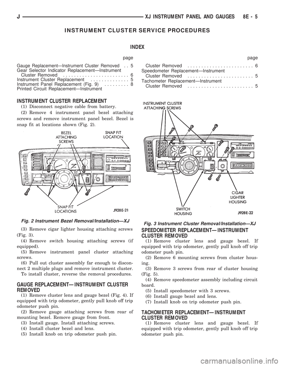
(2) Remove 4 instrument panel bezel attaching
screws and remove instrument panel bezel. Bezel is
snap fit at locations shown (Fig. 2).
(3) Remove cigar lighter housing attaching screws
(Fig. 3).
(4) Remove switch housing attaching screws (if
equipped).
(5) Remove instrument panel cluster attaching
screws.
(6) Pull out cluster assembly far enough to discon-
nect 2 multiple plugs and remove instrument cluster.
To install cluster, reverse the removal procedures.
GAUGE REPLACEMENTÐINSTRUMENT CLUSTER
REMOVED
(1) Remove cluster lens and gauge bezel (Fig. 4). If
equipped with trip odometer, gently pull knob off trip
odometer push pin.
(2) Remove gauge attaching screws from rear of
mounting bezel. Remove gauge from front.
(3) Install gauge. Install attaching screws.
(4) Install cluster bezel and lens.
(5) Install knob on trip odometer push pin.
SPEEDOMETER REPLACEMENTÐINSTRUMENT
CLUSTER REMOVED
(1) Remove cluster lens and gauge bezel. If
equipped with trip odometer, gently pull knob off trip
odometer push pin.
(2) Remove 6 mounting screws from cluster hous-
ing.
(3) Remove 3 screws from rear of cluster housing
(Fig. 5).
(4) Remove speedometer assembly including circuit
board.
(5) Install speedometer with 3 screws.
(6) Install gauge bezel and lens.
(7) Install knob on trip odometer push pin.
TACHOMETER REPLACEMENTÐINSTRUMENT
CLUSTER REMOVED
(1) Remove cluster lens and gauge bezel. If
equipped with trip odometer, gently pull knob off trip
odometer push pin.
Fig. 2 Instrument Bezel Removal/InstallationÐXJFig. 3 Instrument Cluster Removal/InstallationÐXJ
JXJ INSTRUMENT PANEL AND GAUGES 8E - 5
Page 355 of 1784

INSTRUMENT PANEL REPLACEMENT (Fig. 9)
(1) Disconnect negative cable from battery.
(2) Remove:
²Parking brake release handle
²lower heat/AC duct below steering column
²ash receiver²lower instrument panel (Fig. 10)
²cluster bezel
²cluster assembly
²clock (if equipped)
²radio and heater control panel
²instrument panel switches
²headlamp switch
Fig. 8 Gear Selector Indicator
Fig. 9 Instrument Panel Exploded View
Fig. 10 Lower Instrument Panel Removal/Installation
8E - 8 XJ INSTRUMENT PANEL AND GAUGESJ
Page 364 of 1784

INSTRUMENT CLUSTER SERVICE PROCEDURES
INDEX
page page
Headlamp Switch/Illumination Rheostat........ 21
Indicator Bezel Replacement................ 17
Instrument Cluster Bulb Replacement......... 19
Instrument Cluster Replacement............. 17Printed Circuit Replacement................ 19
Rear Defogger/Fog Lamp/Rear Wiper Switches . . 21
Speedometer Replacement................. 17
Tachometer Replacement.................. 17
INSTRUMENT CLUSTER REPLACEMENT
(1) Remove 6 shroud screws (Fig. 1).
(2) Slide shroud toward steering wheel.
(3) Remove 3 screws holding right side switch
panel (Fig. 2).
(4) Remove 3 screws holding left side switch bezel.(5) Remove 2 screws holding cluster in place.
(6) Lift up top of cluster. Roll cluster out between
steering column and instrument panel far enough to
reach connector located behind tachometer.
(7) Disconnect cluster connector and remove clus-
ter (Fig. 3).
(8) To install cluster, reverse the removal proce-
dures.
TACHOMETER REPLACEMENT
(1) Disconnect negative cable from battery.
(2) Remove instrumentation shroud (Fig. 1). Refer
to Instrument Cluster Replacement.
(3) Remove cluster as described in Instrument
Cluster replacement.
(4) Remove 3 screws and tachometer lens (Fig. 4).
(5) Gently pry up clip to release lens from bezel
(Fig. 5).
(6) Remove 3 screws from rear of housing (Fig. 6).
Remove tachometer.
(7) Install tachometer with 3 screws.
(8) Snap lens into place.
(9) Install lens with 3 screws.
(10) To install the cluster, reverse the removal pro-
cedures.
SPEEDOMETER REPLACEMENT
(1) Disconnect negative cable from battery.
(2) Remove instrument shroud (Fig. 1). Refer to In-
strument Cluster Replacement.
(3) Remove cluster as described in Instrument
Cluster Replacement.
(4) Remove 3 screws and speedometer lens (Fig. 7).
(5) Gently pry up clip to release lens from bezel
(Fig. 5).
(6) Remove 3 screws from rear of housing (Fig. 8).
Remove speedometer.
(7) Install speedometer with 3 screws.
(8) Snap lens into place.
(9) Install lens with 3 screws.
(10) To install the cluster, reverse the removal pro-
cedures.
INDICATOR BEZEL REPLACEMENT
(1) Disconnect negative cable from battery.
(2) Remove instrumentation shroud (Fig. 1).
(3) Remove 3 screws and tachometer lens (Fig. 4).
Fig. 2 Cluster Removal
Fig. 1 Instrument Shroud Removal/Installation
JYJ INSTRUMENT PANEL AND GAUGES 8E - 17
Page 366 of 1784
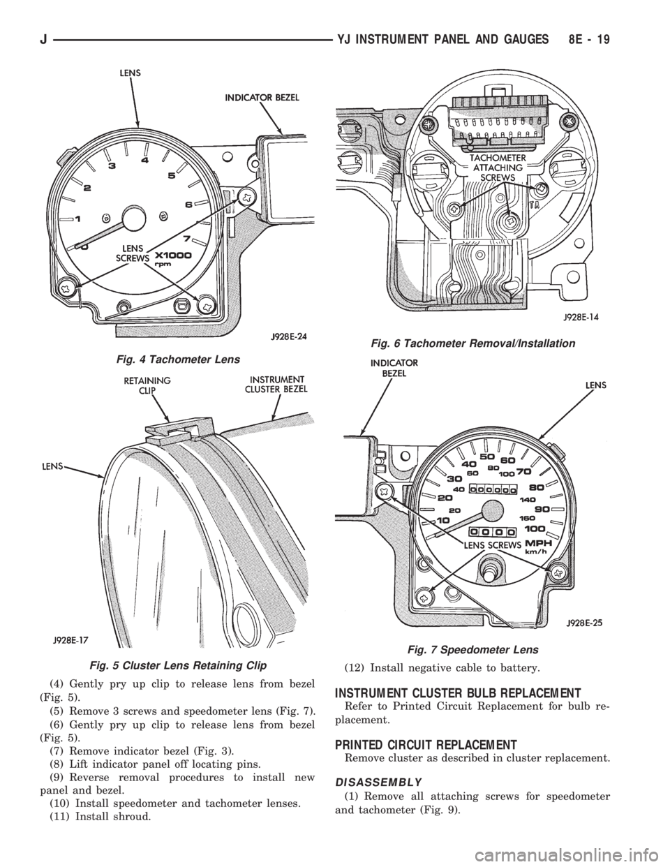
(4) Gently pry up clip to release lens from bezel
(Fig. 5).
(5) Remove 3 screws and speedometer lens (Fig. 7).
(6) Gently pry up clip to release lens from bezel
(Fig. 5).
(7) Remove indicator bezel (Fig. 3).
(8) Lift indicator panel off locating pins.
(9) Reverse removal procedures to install new
panel and bezel.
(10) Install speedometer and tachometer lenses.
(11) Install shroud.(12) Install negative cable to battery.INSTRUMENT CLUSTER BULB REPLACEMENT
Refer to Printed Circuit Replacement for bulb re-
placement.
PRINTED CIRCUIT REPLACEMENT
Remove cluster as described in cluster replacement.
DISASSEMBLY
(1) Remove all attaching screws for speedometer
and tachometer (Fig. 9).
Fig. 4 Tachometer Lens
Fig. 5 Cluster Lens Retaining Clip
Fig. 6 Tachometer Removal/Installation
Fig. 7 Speedometer Lens
JYJ INSTRUMENT PANEL AND GAUGES 8E - 19