1994 JEEP CHEROKEE battery replacement
[x] Cancel search: battery replacementPage 408 of 1784
WINDSHIELD WIPERS
CONTENTS
page page
WIPER CONTROL SWITCH REPLACEMENT . . 15
WIPER SWITCH TESTING................ 19XJ .................................... 1
YJ .................................... 8
XJ
INDEX
page page
Diagnosing Rear Wiper..................... 6
Diagnosing Rear Wiper Washer.............. 6
Diagnosing Windshield Washer (Intermittent)..... 5
Diagnosing Windshield Washer (Non-Intermittent) . 4
Diagnosing Windshield Wipers............... 11
Front Wipers/Washers...................... 1
Intermittent Wiper Module................... 5
Liftgate Wiper............................ 5Liftgate Wiper Switch Replacement............ 6
Rear Wiper/Washer Switch Testing............ 7
Torque Specifications XJ.................... 7
Washer Pump Replacement................. 6
Washer Pump ReplacementÐLeft Hand Drive.... 2
Washer Pump ReplacementÐRight Hand Drive . . 3
Windshield Wiper Motor.................... 2
FRONT WIPERS/WASHERS
GENERAL
Two-speed electric windshield wipers and electric
washers are standard equipment. An optional inter-
mittent wiper system provides a pause between wipe
cycles for use during conditions of very light precipi-
tation.
The windshield wipers can be operated with the
windshield wiper switch only when the ignition
switch is in the ON or ACCESSORY position. A cir-
cuit breaker located in the fuse block protects the cir-
cuitry of the wiper system.
WIPERS
The standard windshield wiper circuit contains
three components; wiper/washer switch, motor, and
front washer pump. Both standard and intermittent
circuits are the same, except that the intermittent
circuit requires a module and delay resistance in the
wiper switch. Both circuits receive battery feed from,
and are protected by a 5.5 amp circuit breaker.
In the standard wiper circuit, the switch connects
the motor directly to battery feed for low and high
speed operation. In the intermittent circuit, the
switch supplies battery feed to the intermittent wiper
module, which then supplies the motor. In the delay
position, the module is connected with the variable
resistor in the wiper switch. The value of the resis-tance is used by the module to charge a capacitor,
which triggers the amount of delay between wipes.
The wiper motor has an arrangement of brushes
providing the two wiper speeds. When the wipers are
turned off, the park switch maintains current to the
motor until the wipers reach the park position on the
windshield.
The park arm in the motor assembly is connected
to the park switch and is driven by the motor. When
the wiper switch is turned off, current flows through
the contact and the module to the motor until the
wipers reach the park position.
CAUTION: The wiper arms and blades must not be
moved manually from side to side or damage may
result.
WASHERS
With the washer switch ON, current flows through
the washer pump to ground. The front washer pump
runs as long as the driver holds the switch ON. On
standard wipers, the washer switch automatically
moves the wiper switch to LO when the washer is
turned on. On intermittent wipers, the wiper module
runs the wiper motor on LO. Turning the switch to
OFF stops the wipers.
If the washer knob is depressed while the wiper
switch is in the OFF position, the wiper control will
operate for approximately 3 wipes and automatically
turn OFF.
JWINDSHIELD WIPERS 8K - 1
Page 410 of 1784
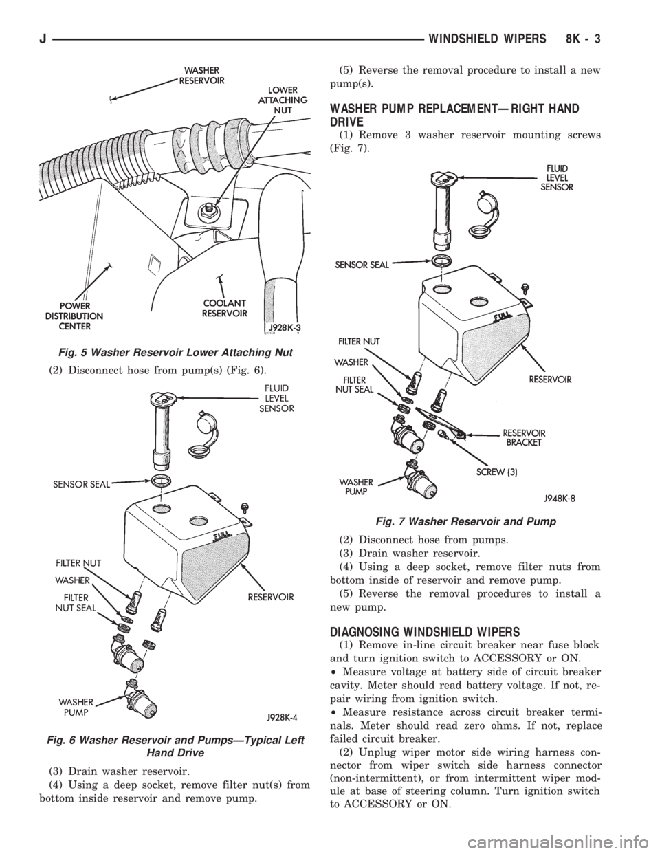
(2) Disconnect hose from pump(s) (Fig. 6).
(3) Drain washer reservoir.
(4) Using a deep socket, remove filter nut(s) from
bottom inside reservoir and remove pump.(5) Reverse the removal procedure to install a new
pump(s).
WASHER PUMP REPLACEMENTÐRIGHT HAND
DRIVE
(1) Remove 3 washer reservoir mounting screws
(Fig. 7).
(2) Disconnect hose from pumps.
(3) Drain washer reservoir.
(4) Using a deep socket, remove filter nuts from
bottom inside of reservoir and remove pump.
(5) Reverse the removal procedures to install a
new pump.
DIAGNOSING WINDSHIELD WIPERS
(1) Remove in-line circuit breaker near fuse block
and turn ignition switch to ACCESSORY or ON.
²Measure voltage at battery side of circuit breaker
cavity. Meter should read battery voltage. If not, re-
pair wiring from ignition switch.
²Measure resistance across circuit breaker termi-
nals. Meter should read zero ohms. If not, replace
failed circuit breaker.
(2) Unplug wiper motor side wiring harness con-
nector from wiper switch side harness connector
(non-intermittent), or from intermittent wiper mod-
ule at base of steering column. Turn ignition switch
to ACCESSORY or ON.
Fig. 5 Washer Reservoir Lower Attaching Nut
Fig. 6 Washer Reservoir and PumpsÐTypical Left
Hand Drive
Fig. 7 Washer Reservoir and Pump
JWINDSHIELD WIPERS 8K - 3
Page 413 of 1784
(2) Install the mounting screws.
(3) Connect the wiring harness.
(4) Install the pivot pin, seal, bezel and attaching
nut (Fig. 2). Torque nut to 4 Nzm (32 in. lbs.).
(5) Connect interior washer hose.
Lubricate the bezel nipples with a small amount
of water and then install the washer hoses.
(6) Install the liftgate trim panel.
(7) Install the wiper arm assembly and connect the
external washer hose to the bezel.
(8) Slide the clip along the hose until it is over
hose mount.
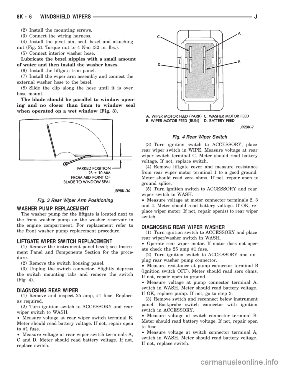
The blade should be parallel to window open-
ing and no closer than 5mm to window seal
when operated on a wet window (Fig. 3).
WASHER PUMP REPLACEMENT
The washer pump for the liftgate is located next to
the front washer pump on the washer reservoir in
the engine compartment. For replacement refer to
the front washer pump replacement procedure.
LIFTGATE WIPER SWITCH REPLACEMENT
(1) Remove the instrument panel bezel; see Instru-
ment Panel and Components Section for the proce-
dure.
(2) Remove the switch housing panel.
(3) Unplug the switch connector. Slightly depress
the switch mounting tabs and remove the switch
(Fig. 4).
DIAGNOSING REAR WIPER
(1) Remove and inspect 25 amp, #1 fuse. Replace
as required.
(2) Turn ignition switch to ACCESSORY and rear
wiper switch to WASH.
²Measure voltage at rear wiper switch terminal B.
Meter should read battery voltage. If not, repair open
to #1 fuse.
²Measure voltage at rear wiper switch terminals A,
C and D. Meter should read battery voltage. If not,
replace switch.(3) Turn ignition switch to ACCESSORY, place
rear wiper switch in WIPE. Measure voltage at rear
wiper switch terminal C. Meter should read battery
voltage. If not, replace switch.
(4) Remove liftgate cover and measure resistance
from rear wiper motor terminal 1 to a good ground.
Meter should read zero ohms. If not, repair open to
ground splice.
(5) Turn ignition switch to ACCESSORY and rear
wiper switch to WASH.
²Measure voltage at motor connector terminals 2, 3
and 4. Meter should read battery voltage. If OK, re-
place wiper motor. If not, repair open(s) to rear wiper
switch.
DIAGNOSING REAR WIPER WASHER
(1) Turn ignition switch to ACCESSORY and place
rear wiper/washer switch in WASH.
²Operate rear wiper motor. If motor does not oper-
ate check the 25 amp #1 fuse.
(2) Turn ignition switch to ACCESSORY and un-
plug rear washer pump connector.
²Measure resistance at pump connector terminal B
(ignition switch OFF). Meter should read zero ohms.
If not, repair open to ground.
²Measure voltage at pump connector terminal A,
switch in WASH. Meter should read battery voltage.
If OK, replace pump. If not, go to step 3.
(3) Remove switch and reconnect below instrument
panel. Backprobe switch connector with ignition
switch in ACCESSORY.
²Measure voltage at switch connector terminal B.
Meter should read battery voltage. If not, repair open
to fuse.
²Measure voltage at switch connector terminal A,
switch in WASH. Meter should read battery voltage.
If not, replace switch.
Fig. 3 Rear Wiper Arm Positioning
Fig. 4 Rear Wiper Switch
8K - 6 WINDSHIELD WIPERSJ
Page 415 of 1784
YJ
INDEX
page page
Diagnosing Windshield Wipers............... 11
Diagnosing Intermittent Windshield Washer..... 12
Diagnosing Non-Intermittent Windshield Washer . 12
Diagnosing Rear Wiper/Washer.............. 14
Front Wiper Arm and Pivot Assembly Replacement . 9
Front Wiper Arm Replacement............... 8
Front Wiper Blade Replacement.............. 8
Front Wiper Motor........................ 10Front Wipers/Washers General Information...... 8
Rear Washer Pump Replacement............ 13
Rear Wiper Arm Replacement............... 12
Rear Wiper Motor Replacement.............. 13
Rear Wiper Switch Replacement............. 13
Rear Wiper/Washer Switch Testing........... 14
Washer Nozzle Replacement................ 13
Washer Pump Replacement................ 11
FRONT WIPERS/WASHERS GENERAL
INFORMATION
The non-intermittent windshield wiper circuit con-
tains three components; control switch, motor and
washer pump. The intermittent circuit contains the
same components and a wiper module that provides
the delay function. Both circuits receive battery feed
from and are protected by a 5.3 amp circuit breaker.
In the non-intermittent wiper circuit, the switch
connects the motor directly to ignition feed for low
and high speed operation. In the intermittent circuit,
the switch supplies ignition feed to the delay module,
which then supplies the motor. In the delay position,
the module is connected with the variable resistor in
the wiper switch. The value of the resistance is used
by the solid state module to charge a capacitor,
which triggers the amount of delay between wipes.
The wiper motor has an arrangement of brushes
providing the two wiper speeds. When the wipers are
turned off, the park switch maintains current to the
motor until the wipers reach the park position on the
windshield.
The washer pump receives ignition feed either di-
rectly from the wiper switch or from the intermittent
module. In either case the electric motor will drive
the washer pump.
The wiper motor is mounted on the lower left cor-
ner of the windshield.
FRONT WIPER BLADE REPLACEMENT
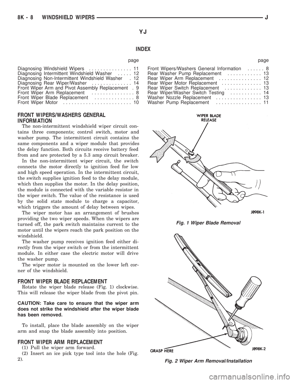
Rotate the wiper blade release (Fig. 1) clockwise.
This will release the wiper blade from the pivot pin.
CAUTION: Take care to ensure that the wiper arm
does not strike the windshield after the wiper blade
has been removed.
To install, place the blade assembly on the wiper
arm and snap the blade assembly into position.
FRONT WIPER ARM REPLACEMENT
(1) Pull the wiper arm forward.
(2) Insert an ice pick type tool into the hole (Fig.
2).
Fig. 1 Wiper Blade Removal
Fig. 2 Wiper Arm Removal/Installation
8K - 8 WINDSHIELD WIPERSJ
Page 418 of 1784
(2) Remove the windshield holddown bolts in the
lower corners of the instrument panel.
(3) Remove wiper motor mounting screws (Fig. 4).
(4) Remove wiper motor harness retaining clip lo-
cated on bottom of windshield.
(5) Disconnect the wiper linkage drive arm (Fig. 5)
(6) Grasp the motor and pull the motor and drive
arm out of the access hole (Fig. 6).
(7) Pry the drive arm off the motor pivot. DO NOT
remove the pivot attaching nut (Fig. 7).
(8) Remove 2 screws holding intermittent wipe
module bracket to bottom of instrument panel.
(9) Reach up behind instrument panel and discon-
nect wiper motor harness.
(10) Remove wiper motor.
INSTALLATION
(1) Install wire harness through hole in top of in-
strument panel.
(2) Connect wiper motor connector behind instru-
ment panel.
(3) Install intermittent wipe module bracket to
bottom of instrument panel.
(4) Turn wipers on to allow motor to cycle to park
position.
(5) Install wiper linkage drive arm onto motor
(Fig. 8).
(6) Install motor and drive arm in the windshield
frame.
(7) Connect wiper linkage drive arm to pivot shaft
(Fig. 9).
(8) Install motor mounting screws. Tighten screws
to 10.5 Nzm (96 in. lbs.).
(9) Install wire harness retaining clip on bottom of
windshield.
Be sure wire harness is not pinched or cut when
windshield frame is rotated to upright position.
(10) Raise windshield to upright position and in-
stall left and right windshield holddown bolts.
(11) Install the necessary top components on wind-
shield frame.
WASHER PUMP REPLACEMENT
(1) Remove 3 washer reservoir mounting screws
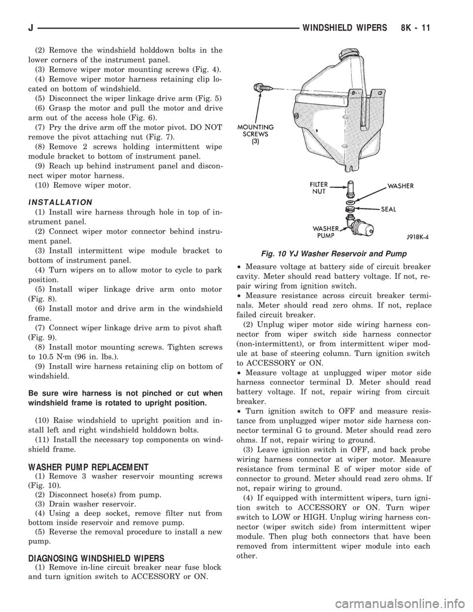
(Fig. 10).
(2) Disconnect hose(s) from pump.
(3) Drain washer reservoir.
(4) Using a deep socket, remove filter nut from
bottom inside reservoir and remove pump.
(5) Reverse the removal procedure to install a new
pump.
DIAGNOSING WINDSHIELD WIPERS
(1) Remove in-line circuit breaker near fuse block
and turn ignition switch to ACCESSORY or ON.²Measure voltage at battery side of circuit breaker
cavity. Meter should read battery voltage. If not, re-
pair wiring from ignition switch.
²Measure resistance across circuit breaker termi-
nals. Meter should read zero ohms. If not, replace
failed circuit breaker.
(2) Unplug wiper motor side wiring harness con-
nector from wiper switch side harness connector
(non-intermittent), or from intermittent wiper mod-
ule at base of steering column. Turn ignition switch
to ACCESSORY or ON.
²Measure voltage at unplugged wiper motor side
harness connector terminal D. Meter should read
battery voltage. If not, repair wiring from circuit
breaker.
²Turn ignition switch to OFF and measure resis-
tance from unplugged wiper motor side harness con-
nector terminal G to ground. Meter should read zero
ohms. If not, repair wiring to ground.
(3) Leave ignition switch in OFF, and back probe
wiring harness connector at wiper motor. Measure
resistance from terminal E of wiper motor side of
connector to ground. Meter should read zero ohms. If
not, repair wiring to ground.
(4) If equipped with intermittent wipers, turn igni-
tion switch to ACCESSORY or ON. Turn wiper
switch to LOW or HIGH. Unplug wiring harness con-
nector (wiper switch side) from intermittent wiper
module. Then plug both connectors that have been
removed from intermittent wiper module into each
other.
Fig. 10 YJ Washer Reservoir and Pump
JWINDSHIELD WIPERS 8K - 11
Page 419 of 1784
CAUTION: DO NOT move the wiper switch to DE-
LAY with the intermittent wiper module removed
from the circuit. If the switch is moved to the DE-
LAY position during the next step, the switch will
be damaged.
²Test wiper operation in LOW and HIGH speed
modes, and test washer operation. If these modes
were inoperative, but are OK now, replace failed in-
termittent wiper module.
(4) To test the wiper/washer switch, see Wiper
Switch Testing. Turn ignition switch to OFF. Posi-
tion the wiper switch as indicated, and back probe
switch side of wiper switch connector. If switch tests
OK, go to step 5. If not, replace switch and go to step
6.
(5) To further test the wiper/washer switch, turn
ignition switch to ACCESSORY or ON. Position the
wiper switch as indicated in the tests below, and
back probe switch side of wiper switch connector.
²Measure voltage at terminal E with wiper switch
in LOW, MIST and with washer switch depressed.
Meter should read battery voltage. If not, replace
switch.
²Measure voltage at connector terminal C with
wiper switch in HIGH. Meter should read battery
voltage. If not, replace switch.
²With wiper switch in LOW or HIGH, measure
voltage at connector terminal F, then move wiper
switch to OFF. Meter shold read battery voltage un-
til wipers park and then zero volts. If OK, go to step
6. If not, check wiring to wiper motor, then go to step
6.
(6) To test the wiper motor, turn the ignition
switch to ACCESSORY or ON. Position the wiper
switch and back probe the motor connector as indi-
cated.
²Wiper switch in any position, measure voltage at
terminal B. Meter should read battery voltage. If not,
repair wiring from circuit breaker.
²Wiper switch in LOW, measure voltage at termi-
nal A. Meter should read battery voltage. If OK, but
wipers do not operate, replace failed wiper motor. If
not, repair wiring from switch or intermittent wiper
module connector.
²Wiper switch in HIGH, measure voltage at termi-
nal H. Meter should read battery voltage. If OK, but
wipers do not operate, replace failed wiper motor. If
not, repair wiring from switch or intermittent wiper
module connector.
²Wiper switch in LOW or HIGH, voltmeter con-
nected to terminal D. Turn wiper switch to OFF and
observe meter. Meter should read battery voltage
when switch goes to OFF, then zero volts after wip-
ers park. If battery voltage is present, but wipers fail
to park; or, if no battery voltage present, replace
failed wiper motor.DIAGNOSING NON-INTERMITTENT WINDSHIELD
WASHER
Refer to Group 8W - Wiring Diagrams.
(1) Measure resistance from washer pump connec-
tor terminal B to a clean chassis ground. Meter
should read zero ohms. If not, repair open between
terminal B and ground.
(2) Turn ignition switch to ON and press washer
switch.
²Measure voltage at switch connector terminal B.
Meter should read battery voltage. If not, replace
wiper/washer switch.
²Measure voltage at washer pump connector termi-
nal A. Meter should read battery voltage. If OK, re-
place pump. If not, repair open between switch
connector and pump connector.
DIAGNOSING INTERMITTENT WINDSHIELD
WASHER
Refer to Group 8W - Wiring Diagrams.
(1) Measure resistance from washer pump connec-
tor terminal B to a clean chassis ground. Meter
should read zero ohms. If not, repair open between
terminal B and ground.
(2) Turn ignition switch to ON and rotate washer
switch tab forward.
²Measure voltage at wiper/washer switch connector
terminal B located at intermittent wipe module.
Meter should read battery voltage. If not, replace
wiper switch.
²Measure voltage at intermittent wipe module con-
nector terminal B (to washer pump). Meter should
read battery voltage. If not, replace intermittent
wipe module.
²Measure voltage at washer pump connector termi-
nal A. Meter should read battery voltage. If OK, re-
place pump. If not, repair open from intermittent
wipe module connector terminal B.
REAR WIPER ARM REPLACEMENT
(1) Install wiper arm remover, Snap On A192 or
equivalent, on wiper arm (Fig. 11). Lift arm and then
remove from pivot shaft.
CAUTION: Do not use a screwdriver or other prying
tool to remove an arm. This may distort it in a way
that will allow it to come off the pivot shaft in the
future, despite how carefully it is installed. NEVER
push or bend the spring clip in the base of the arm
in an attempt to release the arm. This clip is self re-
leasing.
(2) To install, reverse the removal procedure.
(3) Wet the window and check the park position by
operating the wiper motor several times.
8K - 12 WINDSHIELD WIPERSJ
Page 422 of 1784
WIPER CONTROL SWITCH REPLACEMENT
(1) Disconnect negative cable from battery.
(2) Remove horn button with a push and turn mo-
tion.
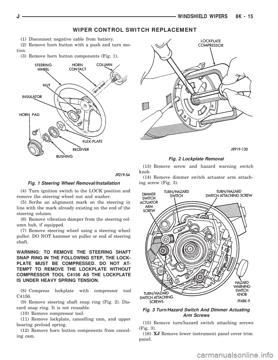
(3) Remove horn button components (Fig. 1).
(4) Turn ignition switch to the LOCK position and
remove the steering wheel nut and washer.
(5) Scribe an alignment mark on the steering in
line with the mark already existing on the end of the
steering column.
(6) Remove vibration damper from the steering col-
umn hub, if equipped.
(7) Remove steering wheel using a steering wheel
puller. DO NOT hammer on puller or end of steering
shaft.
WARNING: TO REMOVE THE STEERING SHAFT
SNAP RING IN THE FOLLOWING STEP, THE LOCK-
PLATE MUST BE COMPRESSED. DO NOT AT-
TEMPT TO REMOVE THE LOCKPLATE WITHOUT
COMPRESSOR TOOL C4156 AS THE LOCKPLATE
IS UNDER HEAVY SPRING TENSION.
(8) Compress lockplate with compressor tool
C4156.
(9) Remove steering shaft snap ring (Fig. 2). Dis-
card snap ring. It is not reusable.
(10) Remove compressor tool.
(11) Remove lockplate, cancelling cam, and upper
bearing preload spring.
(12) Remove horn button components from cancel-
ing cam.(13) Remove screw and hazard warning switch
knob.
(14) Remove dimmer switch actuator arm attach-
ing screw (Fig. 3).
(15) Remove turn/hazard switch attaching screws
(Fig. 3).
(16)XJRemove lower instrument panel cover trim
panel.
Fig. 1 Steering Wheel Removal/Installation
Fig. 2 Lockplate Removal
Fig. 3 Turn/Hazard Switch And Dimmer Actuating
Arm Screws
JWINDSHIELD WIPERS 8K - 15
Page 428 of 1784
LAMPS
CONTENTS
page page
EXTERIOR LAMPS....................... 1
INTERIOR LAMPS...................... 19SPECIFICATIONS....................... 23
EXTERIOR LAMPS
INDEX
page page
Back-up/Rear Turn Signal/Tail Lamp Bulb
Replacement........................... 9
Center High Mounted Stop Lamp (CHMSL)ÐXJ . 10
Center High Mounted Stop Lamp (CHMSL)ÐYJ . 11
Daytime Running Lights (Canada Only)........ 16
DRL Module Replacement.................. 16
Fog Lamp Beam Adjustment................ 12
Fog Lamp Bulb/Element Replacement......... 13
Fog Lamp Replacement................... 15
Fog Lamp Service Information............... 12
Fog Lamp Switch Replacement.............. 14
Fog Lamp Trouble Diagnosis................ 12
Front Park/Turn Signal Lamp Bulb Replacement . . 8
Headlamp Beam Adjustment................. 3
Headlamp Bulb Replacement................ 3
Headlamp Delay Function Trouble DiagnosisÐXJ
Vehicles.............................. 16Headlamp Delay Module ReplacementÐXJ
Vehicles.............................. 16
Headlamp Dimmer Switch Replacement........ 6
Headlamp Switch Replacement............... 4
Headlamp Trouble DiagnosisÐXJ Vehicles...... 1
Headlamp Trouble DiagnosisÐYJ Vehicles...... 2
License Plate Lamp....................... 10
Sentinel Headlamp Delay ModuleÐXJ Vehicles . . 15
Service Information........................ 1
Side Marker Lamp Bulb Replacement.......... 7
Switch Tests............................. 2
Underhood Lamp Bulb Replacement.......... 18
Underhood Lamp Replacement.............. 18
Underhood Lamp Service Information......... 17
SERVICE INFORMATION
Exterior lamp circuits are comprised of the head-
lamp circuit, fog lamp circuit, and tail/side marker/
park lamp circuit. Battery voltage is controlled by
both the headlamp ON/OFF switch and headlamp
dimmer switch.
The dimmer switch functions as a fog lamp switch.
Voltage is applied to the fog lamp switch only when
the dimmer switch is in the low beam position.
HEADLAMP TROUBLE DIAGNOSISÐXJ VEHICLES
LOW AND HIGH BEAM INOPERATIVE BOTH
HEADLAMPS
(1) Place the headlamp switch in the ON position.
(2) Test the 40 amp fuse for continuity. If bad, re-
place fuse.
(3) Insert the test probe into terminal 5 of the
front lamp wire harness connector. Measure the re-
sistance from terminal 5 to body ground. The ohm-
meter should indicate zero ohms. If not OK, repair
the open circuit in the harness to body ground.(4) Disconnect the front lamp wire connector. Mea-
sure resistance between connector terminals 5 and 2.
Next measure between terminal 5 and 7. The ohm-
meter should indicate zero ohms for both measure-
ments. If not OK, replace the headlamp bulbs.
(5) Measure the voltage between the dimmer
switch wire connector terminal 2 and body ground.
The voltmeter should indicate battery voltage. If not
OK, continue with the next step.
The dimmer switch is integral with the turn
signal and is located on the steering column.
The dimmer switch switches the headlamp beam
when the turn signal lever is pulled rearward.
(6) Disconnect the dimmer switch wire connector
and place the headlamp switch in the OFF position.
Measure the resistance from terminal 2 to vehicle
body ground. The ohmmeter should indicate infinite
resistance. If OK, replace the headlamp switch and
continue with the next step. If not OK, repair the
short circuit in the wire harness that leads to termi-
nal 2.
JLAMPS 8L - 1