1994 JEEP CHEROKEE Engine mounts
[x] Cancel search: Engine mountsPage 19 of 1784

In areas of the country where carbon monoxide lev-
els are high, gasolines are being treated with oxy-
genated materials such as MTBE, ETBE and
ethanol.
Chrysler Corporation supports these efforts toward
cleaner air and recommends the use of these gaso-
lines as they become available.
IGNITION CABLES, DISTRIBUTOR CAP AND
ROTOR
REQUIRED IGNITION SYSTEM MAINTENANCE
The ignition cables, distributor cap and rotor must
be replaced after each 96 000-km (60,000-miles). Re-
fer to Group 8DÐIgnition Systems for additional in-
formation.
IGNITION TIMING
The ignition timing for 2.5L and 4.0L engines is
not adjustable. Refer to the specifications listed on
the engine Emission Control Information Label. Re-
fer to Group 25ÐEmission Control Systems for addi-
tional information.
SPARK PLUGS
REQUIRED MAINTENANCE
The spark plugs must be replaced after each 48
000-km (30,000-miles). Refer to the Spark Plugs
chart below and to Group 8DÐIgnition Systems for
additional information.
BATTERY
RECOMMENDED MAINTENANCE
The battery electrolyte level should be checked and
the cable clamps should be inspected for corrosion.
This should be done when the oil is changed and the
oil filter is replaced.
The battery cables should be inspected for abnor-
mal clamp and battery terminal post corrosion. Ser-
vice the terminals and cable clamps as necessary.In addition, the general condition of the battery
should be determined before the start of cold and hot
weather seasons. If the battery condition is marginal
or worse, it should be replaced.
Care should be taken when disposing a bat-
tery after removal from a vehicle. Lead-acid bat-
teries are highly poisonous and, when
indiscriminately disposed, could create a prob-
lem for the environment. Contact the applicable
local city or county government agency to deter-
mine where automobile (lead-acid) batteries can
be properly disposed in the local area.
INSPECTION/SERVICE
WARNING: WEAR SAFETY GLASSES, RUBBER
GLOVES AND PROTECTIVE CLOTHING WHEN HAN-
DLING/SERVICING A BATTERY. THE BATTERY
ELECTROLYTE CONTAINS SULFURIC ACID AND
WILL CAUSE HARM IF IT CONTACTS SKIN, EYES
OR CLOTHING. IT WILL ALSO DAMAGE PAINTED
(AS WELL AS UN-PAINTED) SURFACES OF A VEHI-
CLE. IF SULFURIC ACID CONTACTS ANY OF
THESE, FLUSH IMMEDIATELY WITH LARGE
AMOUNTS OF WATER. IF SULFURIC ACID CON-
TACTS SKIN OR EYES, GET IMMEDIATE MEDICAL
ATTENTION. DO NOT SMOKE IN THE VICINITY OF
A BATTERY. KEEP OPEN FLAMES AND SPARKS
AWAY FROM BATTERY FILLER CAPS BECAUSE
EXPLOSIVE GAS IS ALWAYS PRESENT.
(1) Disconnect the battery negative cable and then
the positive cable.
(2) Clean the battery cable clamps and terminal
posts with a wire brush and a battery terminal
cleaner.
(3) Pry the battery cell filler caps upward to re-
move them and inspect each filler well (low-mainte-
nance batteries only, not applicable to maintenance-
free batteries). It could possibly be necessary to
loosen the battery holddown clamp to remove the
caps. Maintain the electrolyte level above the battery
plates and at the bottom of the filler well ring. Add
distilled water or low-mineral content drinking wa-
ter, if necessary. In freezing weather (below 0ÉC/
32ÉF), add the water just before driving to ensure
that it mixes thoroughly with the electrolyte. This
will prevent it from freezing.
(4) Remove the battery holddown strap and clean
the battery case/battery tray.Clean with bicarbonate
of soda (baking soda) and water. Rinse and dry the
battery case/tray thoroughly after cleaning.
(5) Position the battery in the tray and install the
holddown strap.Do not over-tighten the nuts.
(6) Connect the battery positive cable and then the
negative cable to the battery.
SPARK PLUGS
0 - 18 LUBRICATION AND MAINTENANCEJ
Page 24 of 1784
Under normal driving conditions, manual trans-
mission lube oil should be changed after each 60
000-km (37,500 miles). With severe driving condi-
tions, after each 29 000-km (18,000 miles).
LUBRICANT SPECIFICATION
When it becomes necessary to add to or change the
lube oil in a Jeeptmanual transmission, use SAE
75W-90, API Quality Grade GL-5 gear lubricant.
LUBRICANT LEVEL
The fill-hole plug for all manual transmissions is
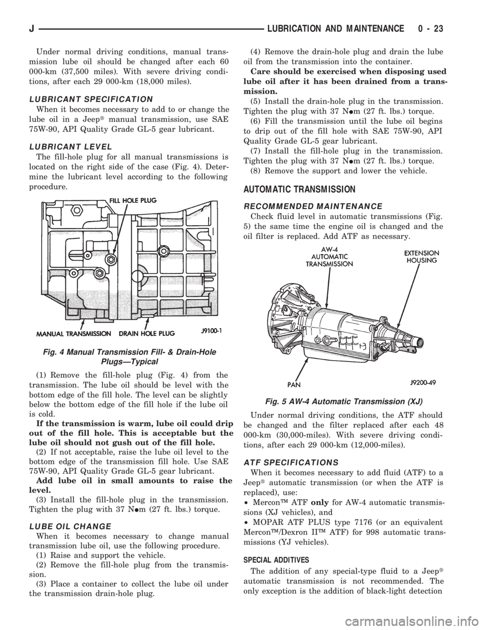
located on the right side of the case (Fig. 4). Deter-
mine the lubricant level according to the following
procedure.
(1) Remove the fill-hole plug (Fig. 4) from the
transmission. The lube oil should be level with the
bottom edge of the fill hole. The level can be slightly
below the bottom edge of the fill hole if the lube oil
is cold.
If the transmission is warm, lube oil could drip
out of the fill hole. This is acceptable but the
lube oil should not gush out of the fill hole.
(2) If not acceptable, raise the lube oil level to the
bottom edge of the transmission fill hole. Use SAE
75W-90, API Quality Grade GL-5 gear lubricant.
Add lube oil in small amounts to raise the
level.
(3) Install the fill-hole plug in the transmission.
Tighten the plug with 37 NIm (27 ft. lbs.) torque.
LUBE OIL CHANGE
When it becomes necessary to change manual
transmission lube oil, use the following procedure.
(1) Raise and support the vehicle.
(2) Remove the fill-hole plug from the transmis-
sion.
(3) Place a container to collect the lube oil under
the transmission drain-hole plug.(4) Remove the drain-hole plug and drain the lube
oil from the transmission into the container.
Care should be exercised when disposing used
lube oil after it has been drained from a trans-
mission.
(5) Install the drain-hole plug in the transmission.
Tighten the plug with 37 NIm (27 ft. lbs.) torque.
(6) Fill the transmission until the lube oil begins
to drip out of the fill hole with SAE 75W-90, API
Quality Grade GL-5 gear lubricant.
(7) Install the fill-hole plug in the transmission.
Tighten the plug with 37 NIm (27 ft. lbs.) torque.
(8) Remove the support and lower the vehicle.
AUTOMATIC TRANSMISSION
RECOMMENDED MAINTENANCE
Check fluid level in automatic transmissions (Fig.
5) the same time the engine oil is changed and the
oil filter is replaced. Add ATF as necessary.
Under normal driving conditions, the ATF should
be changed and the filter replaced after each 48
000-km (30,000-miles). With severe driving condi-
tions, after each 29 000-km (12,000-miles).
ATF SPECIFICATIONS
When it becomes necessary to add fluid (ATF) to a
Jeeptautomatic transmission (or when the ATF is
replaced), use:
²MerconŸ ATFonlyfor AW-4 automatic transmis-
sions (XJ vehicles), and
²MOPAR ATF PLUS type 7176 (or an equivalent
MerconŸ/Dexron IIŸ ATF) for 998 automatic trans-
missions (YJ vehicles).
SPECIAL ADDITIVES
The addition of any special-type fluid to a Jeept
automatic transmission is not recommended. The
only exception is the addition of black-light detection
Fig. 5 AW-4 Automatic Transmission (XJ)
Fig. 4 Manual Transmission Fill- & Drain-Hole
PlugsÐTypical
JLUBRICATION AND MAINTENANCE 0 - 23
Page 27 of 1784
If the transfer case ATF is warm, it is accept-
able for the fluid to drip out of the fill hole. If
the fluid gushes out of the fill hole, the level is
too high.
(3) If the level is low, raise it to the bottom edge of
the fill hole with MOPAR ATF PLUS type 7176 or
an equivalent MerconŸ/Dexron IIŸ ATF.
(4) Install the fill-hole plug. Tighten the plug with
47 NIm (35 ft. lbs.) torque.
(5) Remove the support and lower the vehicle.
FLUID CHANGE
When it becomes necessary to change the ATF in a
Jeepttransfer case, use the following procedure.
(1) Raise and support the vehicle.
(2) Remove the fill-hole plug from the transfer
case.
(3) Place an appropriate container under the trans-
fer case drain-hole plug.
(4) Remove the drain-hole plug and drain the ATF
from the transfer case into the container.
Care should be exercised when disposing used
ATF after it has been drained from a transfer
case.
CAUTION: Do not over-tighten the drain and fill-hole
plugs. Over-tightening can strip the hole threads
and/or crack the aluminum housing.
(5) Install the drain-hole plug in the transfer case.
Tighten the plug with 47 NIm (35 ft. lbs.) torque.
(6) Fill the transfer case to the bottom edge of the
fill hole with MOPAR ATF PLUS type 7176 (or an
equivalent MerconŸ/Dexron IIŸ ATF).
(7) Install the fill-hole plug in the transfer case.
Tighten the plug with 47 NIm (35 ft. lbs.) torque.
(8) Remove the support and lower the vehicle.
FRONT AND REAR AXLES
RECOMMENDED MAINTENANCE
The lubricant level in axle differential housings
should be determined at the same time as the engine
oil is changed and the oil filter is replaced. Add lu-
bricant as necessary.
In addition, with normal driving conditions, the
axle lubricant should be changed after each 48
000-km (30,000-miles). With severe driving condi-
tions, after each 29 000-km (12,000-miles).
LUBRICANT SPECIFICATIONS
For normal vehicle operation, use SAE 75W-90,
API Quality Grade GL-5 gear lubricant in all Jeept
front (4WD only) and rear axles. Vehicles equipped
with a Trac-Loc rear axle also require a friction mod-
ifier additive with the gear lubricant.
When involved in trailer towing applications
use SAE 80W-140, API Quality Grade GL-5 gearlubricant in the rear axle. XJ Vehicles equipped
with a class III trailer hitch require SAE
75W-140 synthetic gear lubricant in the rear
axle.
LUBRICANT LEVEL
Determine the axle differential housing lubricant
level according to the following procedure.
(1) Raise and support the vehicle.
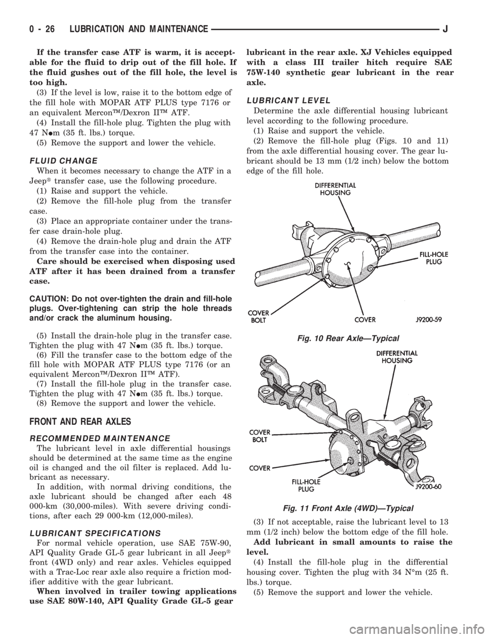
(2) Remove the fill-hole plug (Figs. 10 and 11)
from the axle differential housing cover. The gear lu-
bricant should be 13 mm (1/2 inch) below the bottom
edge of the fill hole.
(3) If not acceptable, raise the lubricant level to 13
mm (1/2 inch) below the bottom edge of the fill hole.
Add lubricant in small amounts to raise the
level.
(4) Install the fill-hole plug in the differential
housing cover. Tighten the plug with 34 NÉm (25 ft.
lbs.) torque.
(5) Remove the support and lower the vehicle.
Fig. 10 Rear AxleÐTypical
Fig. 11 Front Axle (4WD)ÐTypical
0 - 26 LUBRICATION AND MAINTENANCEJ
Page 54 of 1784
level. Where axle bearing damage is slight, the noise
is usually not noticeable at speeds above 30 mph.
LOW SPEED KNOCK
Low speed knock is generally caused by a worn
U-joint or by worn side-gear thrust washers. A worn
pinion gear shaft bore will also cause low speed
knock.
VIBRATION
Vibration at the rear of the vehicle is usually
caused by a:
²Damaged drive shaft
²Missing drive shaft balance weight
²Worn, out-of-balance wheels
²Loose wheel lug nuts
²Worn U-joint
²Loose spring U-bolts
²Loose/broken springs
²Damaged axle shaft bearings
²Loose pinion gear nut
²Excessive pinion yoke run out
²Bent axle shaft
Check for loose or damaged front-end components
or engine/transmission mounts. These componentscan contribute to what appears to be a rear-end vi-
bration. Do not overlook engine accessories, brackets
and drive belts.
All driveline components should be examined be-
fore starting any repair.
Refer to Group 22ÐTires And Wheels for addi-
tional information involving vibration diagnosis.
DRIVELINE SNAP
A snap or clunk noise when the vehicle is shifted
into gear (or the clutch engaged), can be caused by:
²High engine idle speed
²Loose engine/transmission/transfer case mounts
²Worn U-joints
²Loose spring mounts
²Loose pinion gear nut and yoke
²Excessive ring gear backlash
²Excessive differential side gear-to-case clearance
The source of a snap or a clunk noise can be deter-
mined with the assistance of a helper. Raise the ve-
hicle on a hoist with the wheels free to rotate.
Instruct the helper to shift the transmission into
gear. Listen for the noise, a mechanics stethoscope is
helpful in isolating the source of a noise.
JFRONT SUSPENSION AND AXLE 2 - 17
Page 102 of 1784
MULTI-PORT FUEL INJECTION (MFI)ÐCOMPONENT DESCRIPTION/SYSTEM
OPERATION
INDEX
page page
Air Conditioning (A/C) Clutch RelayÐPCM Output.24
Air Conditioning (A/C) ControlsÐPCM Input.... 19
Auto Shut Down (ASD) RelayÐPCM Output.... 24
Automatic Shut Down (ASD) SenseÐPCM Input . 19
Battery VoltageÐPCM Input................ 19
Brake SwitchÐPCM Input.................. 20
Camshaft Position SensorÐPCM Input........ 20
Crankshaft Position SensorÐPCM Input....... 20
Data Link ConnectorÐPCM Input............ 20
Data Link ConnectorÐPCM Output........... 24
EMR LampÐPCM Output.................. 24
Engine Coolant Temperature SensorÐPCM Input . 21
Extended Idle SwitchÐPCM Input............ 21
Fuel InjectorsÐPCM Output................ 25
Fuel Pressure Regulator................... 30
Fuel Pump RelayÐPCM Output............. 25
Fuel Rail............................... 30
General Information....................... 17
Generator FieldÐPCM Output............... 25
Generator LampÐPCM Output.............. 25
Idle Air Control (IAC) MotorÐPCM Output...... 25
Ignition Circuit SenseÐPCM Input............ 21
Ignition CoilÐPCM Output.................. 26Intake Air Temperature SensorÐPCM Input.... 20
Malfunction Indicator LampÐPCM Output...... 26
Manifold Absolute Pressure (MAP) SensorÐ
PCM Input............................ 21
Open Loop/Closed Loop Modes of Operation . . . 27
Overdrive/Override Switch.................. 22
Oxygen (O2S) SensorÐPCM Input........... 22
Park/Neutral SwitchÐPCM Input............. 22
Power Ground........................... 22
Power Steering Pressure SwitchÐPCM Input . . . 22
Powertrain Control Module (PCM)............ 18
Radiator Fan RelayÐPCM Output............ 26
SCI ReceiveÐPCM Input.................. 22
SCI TransmitÐPCM Output................. 26
Sensor ReturnÐPCM Input................. 23
Shift IndicatorÐPCM Output................ 26
Speed ControlÐPCM Input................. 23
Speed ControlÐPCM Output................ 27
TachometerÐPCM Output.................. 27
Throttle Body............................ 29
Throttle Position Sensor (TPS)ÐPCM Input..... 23
Torque Converter Clutch RelayÐPCM Output . . . 27
Vehicle Speed SensorÐPCM Input........... 23
GENERAL INFORMATION
All 2.5L 4 cylinder and 4.0L 6 cylinder engines are
equipped with sequential Multi-Port Fuel Injection
(MFI). The MFI system provides precise air/fuel ra-
tios for all driving conditions.
The Powertrain Control Module (PCM) operates
the fuel system. The PCM was formerly referred to
as the SBEC or engine controller. The PCM is a pre-
programmed, dual microprocessor digital computer.
It regulates ignition timing, air-fuel ratio, emission
control devices, charging system, speed control, air
conditioning compressor clutch engagement and idle
speed. The PCM can adapt its programming to meet
changing operating conditions.
Powertrain Control Module (PCM) Inputsrep-
resent the instantaneous engine operating conditions.
Air-fuel mixture and ignition timing calibrations for
various driving and atmospheric conditions are pre-
programmed into the PCM. The PCM monitors and
analyzes various inputs. It then computes engine fuel
and ignition timing requirements based on these in-
puts. Fuel delivery control and ignition timing will
then be adjusted accordingly.
Other inputs to the PCM are provided by the brake
light switch, air conditioning select switch and the
speed control switches. All inputs to the PCM are
converted into signals.
Electrically operated fuel injectors spray fuel in
precise metered amounts into the intake port directlyabove the intake valve. The injectors are fired in a
specific sequence by the PCM. The PCM maintains
an air/fuel ratio of 14.7 to 1 by constantly adjusting
injector pulse width. Injector pulse width is the
length of time that the injector opens and sprays fuel
into the chamber. The PCM adjusts injector pulse
width by opening and closing the ground path to the
injector.
Manifold absolute pressure (air density) and engine
rpm (speed) are the primary inputs that determine
fuel injector pulse width. The PCM also monitors
other inputs when adjusting air-fuel ratio.
Inputs That Effect Fuel Injector Pulse Width
²Exhaust gas oxygen content
²Engine coolant temperature
²Manifold absolute pressure (MAP)
²Engine speed
²Throttle position
²Battery voltage
²Air conditioning selection
²Transmission gear selection (automatic transmis-
sions only)
²Speed control
The powertrain control module (PCM) adjusts igni-
tion timing by controlling ignition coil operation. The
ignition coil receives battery voltage when the igni-
tion key is in the run or starter position. The PCM
provides a ground for the ignition coil. The coil dis-
JFUEL SYSTEM 14 - 17
Page 850 of 1784
2.5L ENGINE SERVICE PROCEDURES
INDEX
page page
Camshaft............................... 29
Camshaft Pin Replacement................. 31
Crankshaft Main Bearings.................. 40
Cylinder Block........................... 45
Engine AssemblyÐXJ Vehicles.............. 14
Engine AssemblyÐYJ Vehicles.............. 16
Engine Cylinder Head..................... 19
Engine Cylinder Head Cover................ 18
Engine Damper.......................... 13
Engine MountÐRear...................... 12
Engine MountsÐFront..................... 10
General Information........................ 9
Hydraulic Tappets........................ 24Oil Pan ................................ 32
Oil Pump............................... 33
Pistons and Connecting Rods............... 34
Rear Main Oil Seals...................... 44
Rocker Arms............................ 19
Specifications........................... 47
Timing Case Cover....................... 27
Timing Case Cover Oil Seal Replacement...... 26
Timing Chain and Sprockets................ 28
Valve Springs and Oil Seals................ 21
Valve Timing............................ 26
Valves and Valve Springs.................. 22
Vibration Damper........................ 26
GENERAL INFORMATION
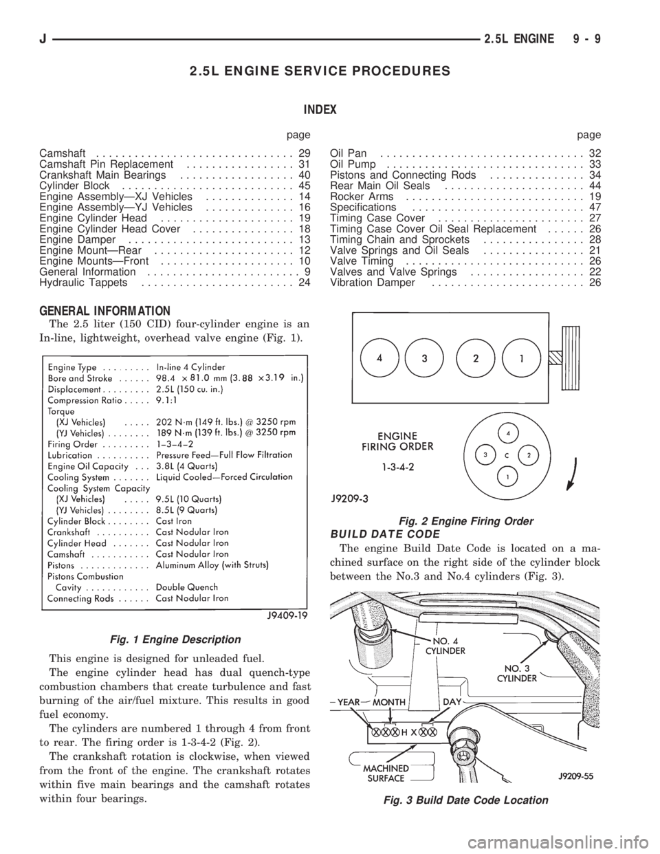
The 2.5 liter (150 CID) four-cylinder engine is an
In-line, lightweight, overhead valve engine (Fig. 1).
This engine is designed for unleaded fuel.
The engine cylinder head has dual quench-type
combustion chambers that create turbulence and fast
burning of the air/fuel mixture. This results in good
fuel economy.
The cylinders are numbered 1 through 4 from front
to rear. The firing order is 1-3-4-2 (Fig. 2).
The crankshaft rotation is clockwise, when viewed
from the front of the engine. The crankshaft rotates
within five main bearings and the camshaft rotates
within four bearings.
BUILD DATE CODE
The engine Build Date Code is located on a ma-
chined surface on the right side of the cylinder block
between the No.3 and No.4 cylinders (Fig. 3).
Fig. 1 Engine Description
Fig. 2 Engine Firing Order
Fig. 3 Build Date Code Location
J2.5L ENGINE 9 - 9
Page 851 of 1784

The digits of the code identify:
(1) 1st DigitÐThe year (4 = 1994).
(2) 2nd & 3rd DigitsÐThe month (01 - 12).
(3) 4th & 5th DigitsÐThe engine type/fuel system/
compression ratio (HX = A 2.5 liter (150 CID) 9.1:1
compression ratio engine with a multi-point fuel in-
jection system).
(4) 6th & 7th DigitsÐThe day of engine build (01 -
31).
FOR EXAMPLE:Code * 401HX23 * identifies a
2.5 liter (150 CID) engine with a multi-point fuel in-
jection system, 9.1:1 compression ratio and built on
January 23, 1994.
OVERSIZE AND UNDERSIZE COMPONENT
CODES
Some engines may be built with oversize or under-
size components such as:
²Oversize cylinder bores.
²Oversize camshaft bearing bores.
²Undersize crankshaft main bearing journals.
²Undersize connecting rod journals.
These engines are identified by a letter code (Fig.
4) stamped on the oil filter boss near the distributor
(Fig. 5).
ENGINE MOUNTSÐFRONT
The front mounts support the engine at each side.
These supports are made of resilient rubber.
REMOVALÐXJ VEHICLES
(1) Disconnect negative cable from battery.
(2) Raise the vehicle.
(3) Support the engine.
(4) Remove through bolt nut (Fig. 6). DO NOT re-
move the through bolt.
(5) Remove the retaining bolts/nuts from the sup-
port cushions (Fig. 6).
(6) Remove the through bolt.
(7) Remove the support cushions.
INSTALLATIONÐXJ VEHICLES
(1) If the engine support bracket was removed, po-
sition the LEFT bracket (Fig. 6) and the RIGHT
bracket with generator brace (Fig. 7) onto the cylin-
der block. Install the bolts and stud nuts.
(a) RIGHT SIDE (Fig. 7)ÐTighten the bolts to
61 Nzm (45 ft. lbs.) torque. Tighten the stud nuts to
46 Nzm (34 ft. lbs.) torque.
(b) LEFT SIDE (Fig. 6)ÐTighten the bolts to 61
Nzm (45 ft. lbs.) torque.
(2) If the support cushion brackets were removed,
position the brackets onto the lower front sill (Figs. 6
and 8). Install the bolts and stud nuts. Tighten the
bolts to 54 Nzm (40 ft. lbs.) torque and the stud nuts
to 41 Nzm (30 ft. lbs.) torque.
(3) Place the support cushions onto the support
cushion brackets (Fig. 6). Tighten the right support
cushion nuts to 65 Nzm (48 ft. lbs.) torque. Tighten
the left support cushion bolt/nut to 41 Nzm (30 ft.
lbs.) torque.
Fig. 4 Oversize and Undersize Component Codes
Fig. 5 Oversize and Undersize Component Code
Location
9 - 10 2.5L ENGINEJ
Page 852 of 1784
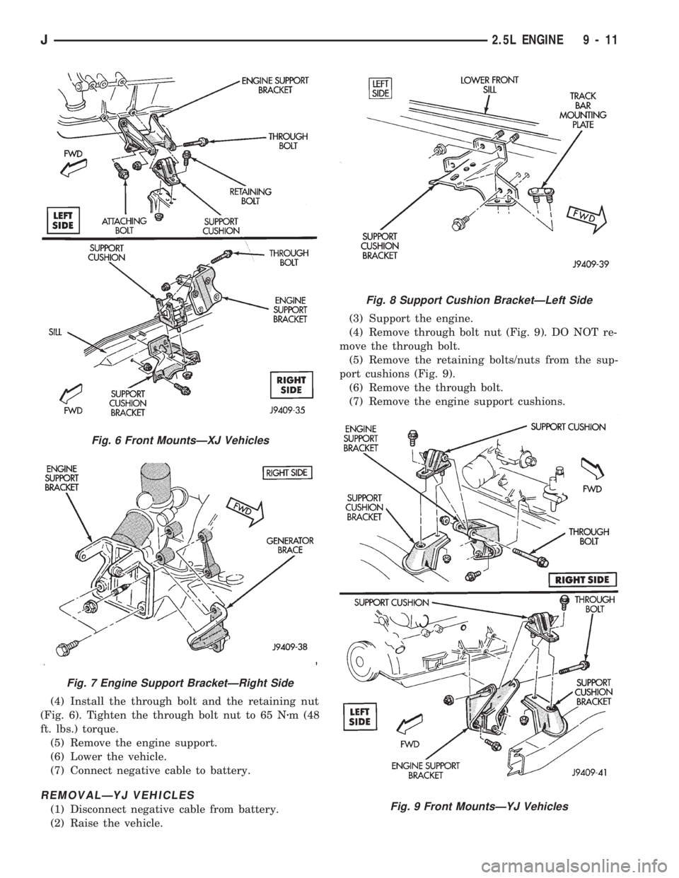
(4) Install the through bolt and the retaining nut
(Fig. 6). Tighten the through bolt nut to 65 Nzm (48
ft. lbs.) torque.
(5) Remove the engine support.
(6) Lower the vehicle.
(7) Connect negative cable to battery.
REMOVALÐYJ VEHICLES
(1) Disconnect negative cable from battery.
(2) Raise the vehicle.(3) Support the engine.
(4) Remove through bolt nut (Fig. 9). DO NOT re-
move the through bolt.
(5) Remove the retaining bolts/nuts from the sup-
port cushions (Fig. 9).
(6) Remove the through bolt.
(7) Remove the engine support cushions.
Fig. 6 Front MountsÐXJ Vehicles
Fig. 7 Engine Support BracketÐRight Side
Fig. 8 Support Cushion BracketÐLeft Side
Fig. 9 Front MountsÐYJ Vehicles
J2.5L ENGINE 9 - 11