1994 JEEP CHEROKEE traction control
[x] Cancel search: traction controlPage 157 of 1784

when the cover is off. The second involves adding to,
or filling the cylinder reservoirs with a non-recom-
mended fluid.
Brake fluid contaminated with only dirt, or debris
usually retains a normal appearance. In some cases,
the foreign material will remain suspended in the
fluid and be visible. The fluid and foreign material
can be removed from the reservoir with a suction
gun but only if the brakes have not been applied. If
the brakes are applied after contamination, system
flushing will be required. The master cylinder may
also have to be disassembled, cleaned and the piston
seals replaced. Foreign material lodged in the reser-
voir compensator/return ports can cause brake drag
by restricting fluid return after brake application.
Brake fluid contaminated by a non-recommended
fluid will usually be discolored, milky, oily looking,
or foamy. In some cases, it may even appear as if the
fluid contains sludge.However, remember that
brake fluid will darken in time and occasionally
be cloudy in appearance. These are normal con-
ditions and should not be mistaken for contami-
nation.
If some type of oil has been added to the system,
the fluid will separate into distinct layers. To verify
this, drain off a sample with a clean suction gun.
Then pour the sample into a glass container and ob-
serve fluid action. If the fluid separates into distinct
layers, it is definitely contaminated.
The only real correction for contamination by non-
recommended fluid is to flush the entire hydraulic
system and replace all the seals.
BRAKE NOISE
Squeak/Squeal
Brake squeak or squeal may be due to linings that
are wet or contaminated with brake fluid, grease, or
oil. Glazed linings and rotors with hard spots can
also contribute to squeak. Dirt and foreign material
embedded in the brake lining will also cause squeak/
squeal.
A very loud squeak or squeal is frequently a sign
of severely worn brake lining. If the lining has worn
through to the brakeshoes in spots, metal-to-metal
contact occurs. If the condition is allowed to continue,
rotors can become so scored that replacement is nec-
essary.
Thump/Clunk
Thumping or clunk noises during braking are fre-
quentlynotcaused by brake components. In many
cases, such noises are caused by loose or damaged
steering, suspension, or engine components. How-
ever, calipers that bind on the slide surfaces can gen-
erate a thump or clunk noise. In addition, worn out,
improperly adjusted, or improperly assembled rear
brakeshoes can also produce a thump noise.Chatter/Shudder
Brake chatter, or shudder is usually caused by
loose or worn components, or glazed/burnt lining. Ro-
tors with hard spots can also contribute to chatter.
Additional causes of chatter are out of tolerance ro-
tors, brake lining not securely attached to the shoes,
loose wheel bearings and contaminated brake lining.
BRAKELINING CONTAMINATION
Brakelining contamination is usually a product of
leaking calipers or wheel cylinders, driving through
deep water puddles, or lining that has become cov-
ered with grease and grit during repair.
WHEEL AND TIRE PROBLEMS
Some conditions attributed to brake components
may actually be caused by a wheel or tire problem.
A damaged wheel can cause shudder, vibration and
pull. A worn or damaged tire can also cause pull.
Severely worn tires with very little tread left can
produce a condition similar to grab as the tire loses
and recovers traction.
Flat-spotted tires can cause vibration and wheel
tramp and generate shudder during brake operation.
A tire with internal damage such as a severe
bruise or ply separation can cause pull and vibration.
DIAGNOSING PARKING BRAKE PROBLEMS
Adjustment Mechanism
Parking brake adjustment is controlled by a
cable tensioner mechanism. This applies to 1991
through 1994 YJ models and 1992 and later XJ
models. The cable tensioner, once adjusted at
the factory, will not need further adjustment un-
der normal circumstances. There are only two
instances when adjustment is required. The first
is when a new tensioner, or cables have been in-
stalled. And the second, is when the tensioner
and cables are disconnected for access to other
brake components.
Parking Brake problem Causes
In most cases, the actual cause of an improperly
functioning parking brake (too loose/too tight/wont
hold), can be traced to a drum brake component.
The leading cause of improper parking brake
operation, is excessive clearance between the
brakeshoes and the drum surface. Excessive
clearance is a result of: lining and/or drum wear;
oversize drums; or inoperative shoe adjuster
components.
Excessive parking brake lever travel (sometimes
described as a loose lever or too loose condition), is
the result of worn brakeshoes/drums, improper
brakeshoe adjustment, or mis-assembled brake parts.
A ``too loose'' condition can also be caused by inop-
erative brakeshoe adjusters. If the adjusters are mis-
5 - 10 BRAKESJ
Page 171 of 1784

DISC BRAKES
INDEX
page page
Caliper Assembly........................ 29
Caliper Cleaning and Inspection............. 28
Caliper Disassembly...................... 27
Caliper Installation........................ 30
Caliper Operation and Wear Compensation..... 24
Caliper Removal......................... 27
Disc Brake Rotor Refinishing................ 32
Disc Brake Rotor Runout................... 31Disc Brake Rotor Thickness................ 31
Disc Brake Rotor Thickness Variation......... 31
Disc Brakeshoe Installation................. 26
Disc Brakeshoe Removal.................. 25
General Information....................... 24
Rotor Installation......................... 30
Rotor Removal.......................... 30
Wheel Nut Tightening..................... 32
GENERAL INFORMATION
1994 Jeep XJ/YJ models are equipped with single
piston, floating-type disc brake calipers. Ventilated,
cast rotors are used for all applications.
The disc brake calipers are supported in mounting
arms that are an integral part of the steering
knuckle. The calipers slide on mounting bolts that
also attach the calipers to the steering knuckle.
CALIPER OPERATION AND WEAR COMPENSATION
Caliper Operation
The significant feature of single piston caliper op-
eration is that the calipers are free to slide laterally
on the mounting bolts. It is the freedom of lateral
movement that allows continous compensation for
lining wear.
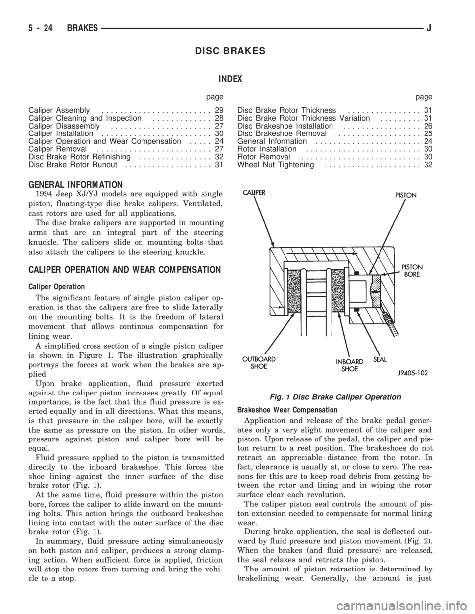
A simplified cross section of a single piston caliper
is shown in Figure 1. The illustration graphically
portrays the forces at work when the brakes are ap-
plied.
Upon brake application, fluid pressure exerted
against the caliper piston increases greatly. Of equal
importance, is the fact that this fluid pressure is ex-
erted equally and in all directions. What this means,
is that pressure in the caliper bore, will be exactly
the same as pressure on the piston. In other words,
pressure against piston and caliper bore will be
equal.
Fluid pressure applied to the piston is transmitted
directly to the inboard brakeshoe. This forces the
shoe lining against the inner surface of the disc
brake rotor (Fig. 1).
At the same time, fluid pressure within the piston
bore, forces the caliper to slide inward on the mount-
ing bolts. This action brings the outboard brakeshoe
lining into contact with the outer surface of the disc
brake rotor (Fig. 1).
In summary, fluid pressure acting simultaneously
on both piston and caliper, produces a strong clamp-
ing action. When sufficient force is applied, friction
will stop the rotors from turning and bring the vehi-
cle to a stop.Brakeshoe Wear Compensation
Application and release of the brake pedal gener-
ates only a very slight movement of the caliper and
piston. Upon release of the pedal, the caliper and pis-
ton return to a rest position. The brakeshoes do not
retract an appreciable distance from the rotor. In
fact, clearance is usually at, or close to zero. The rea-
sons for this are to keep road debris from getting be-
tween the rotor and lining and in wiping the rotor
surface clear each revolution.
The caliper piston seal controls the amount of pis-
ton extension needed to compensate for normal lining
wear.
During brake application, the seal is deflected out-
ward by fluid pressure and piston movement (Fig. 2).
When the brakes (and fluid pressure) are released,
the seal relaxes and retracts the piston.
The amount of piston retraction is determined by
brakelining wear. Generally, the amount is just
Fig. 1 Disc Brake Caliper Operation
5 - 24 BRAKESJ
Page 1404 of 1784

NP242 TRANSFER CASE
INDEX
page page
Cleaning and Inspection.................. 305
General Information...................... 293
Shift Linkage Adjustment.................. 296
Speedometer Service.................... 296
Transfer Case Assembly.................. 306
Transfer Case Disassembly and Overhaul..... 297Transfer Case Fill Level.................. 294
Transfer Case Identification................ 293
Transfer Case Installation................. 296
Transfer Case Lubricant.................. 294
Transfer Case Removal................... 296
GENERAL INFORMATION
The NP242 is a both a full and part time transfer
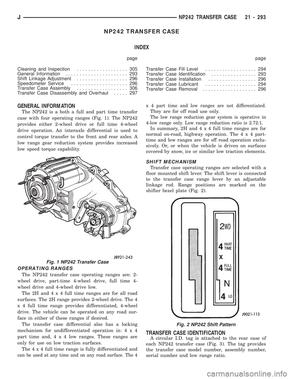
case with four operating ranges (Fig. 1). The NP242
provides either 2-wheel drive or full time 4-wheel
drive operation. An interaxle differential is used to
control torque transfer to the front and rear axles. A
low range gear reduction system provides increased
low speed torque capability.
OPERATING RANGES
The NP242 transfer case operating ranges are: 2-
wheel drive, part-time 4-wheel drive, full time 4-
wheel drive and 4-wheel drive low.
The2Hand4x4full time ranges are for all road
surfaces. The 2H range provides 2-wheel drive. The 4
x 4 full time range provides differentiated, 4-wheel
drive. The vehicle can be operated on any road sur-
face in either of these ranges if desired.
The transfer case differential also has a locking
mechanism for undifferentiated operation in:4x4
part time and,4x4lowranges. These ranges are
only for use on low traction surfaces.
The4x4full time range is fully differentiated and
can be used at any time and on any road surface. The 4x 4 part time and low ranges are not differentiated.
They are for off road use only.
The low range reduction gear system is operative in
4-low range only. Low range reduction ratio is 2.72:1.
In summary, 2H and4x4full time ranges are for
normal on-road, highway operation. The4x4part-
time and low ranges are for off road operation exclu-
sively. Or, or when the vehicle is driven on surfaces
covered by snow, ice or similar low traction elements.
SHIFT MECHANISM
Transfer case operating ranges are selected with a
floor mounted shift lever. The shift lever is connected
to the transfer case range lever by an adjustable
linkage rod. Range positions are marked on the
shifter bezel plate (Fig. 2).
TRANSFER CASE IDENTIFICATION
A circular I.D. tag is attached to the rear case of
each NP242 transfer case (Fig. 3). The tag provides
the transfer case model number, assembly number,
serial number and low range ratio.
Fig. 1 NP242 Transfer Case
Fig. 2 NP242 Shift Pattern
JNP242 TRANSFER CASE 21 - 293