1994 JEEP CHEROKEE driver seat adjustment
[x] Cancel search: driver seat adjustmentPage 306 of 1784

OVERHEAD CONSOLE
CONTENTS
page page
COMPASS REPAIR PROCEDURES.......... 4
CONSOLE REPAIR PROCEDURES........... 6
DESCRIPTION........................... 1DIAGNOSTIC PROCEDURES............... 1
THERMOMETER AND SENSOR SYSTEM REPAIR
PROCEDURES......................... 6
DESCRIPTION
The overhead console includes:
²a compass/temperature display
²reading and courtesy lights for the front and rear
seats
²the receiver for the keyless entry system
²storage compartment for remote garage door
opener
²storage compartment for sunglasses.
COMPASS
The compass will display the direction the vehicle
is pointed, using the eight major compass headings
(Examples: North is ``N'', Northeast is ``NE''). It does
not display the headings in actual degrees. The dis-
play is turned on/off using the TEMP/COMP button
on the left of the display.
The compass is a self calibrating unit that should
not require recalibration. The only calibration that
may prove necessary is to drive the vehicle in 3 com-
plete circles, on level ground, in not less than 48 sec-
onds. This will ``reorient'' the unit to its vehicle. The
unit also will compensate for magnetism the vehicle
may acquire during its life. Care should be used to
avoid putting anything magnetic on the roof of the
vehicle.
The unit can compensate for some magnetic fields
in the body. The use of magnetic attachments like
antenna mounts or repair order ``hats'' placed di-
rectly on the roof can exceed the compensation abil-
ity of the unit. Magnetic bit drivers used on the
fasteners to hold the assembly to the roof header can
also affect operation. If the vehicle roof should be-
come magnetized, then the degaussing and calibra-
tion procedures may be required to restore proper
operation.
If the compass functions but accuracy is suspect, it
may be necessary to perform a variation adjustment.
This procedure allows the unit to accommodate vari-
ations in the earth's magnetic field strength based on
geographic location.
If the compass has blanked out and only CAL
appears, degaussing may be necessary to re-
move residual magnetic fields.
THERMOMETER
The ambient temperature display can be changed
from Fahrenheit to Celsius using the U.S./METRIC
button on the right of the display. The temperature
reported is not an instant reading of conditions but
an average temperature. It may take the unit several
minutes to react to a major change such as driving
out of a heated garage into winter temperatures.
When the ignition switch is turned OFF, the last
displayed temperature reading stays in memory.
When the ignition switch is turned ON again the
thermometer will display the memory temperature
for one minute; then update the display to the actual
temperature within five minutes.
READING AND COURTESY LAMPS
All reading and courtesy lamps in the overhead
console are activated by the door courtesy circuit.
When all four doors and the liftgate are closed the
lamps can be activated by depressing the correspond-
ing lens. When any door or the liftgate is open, the
switches are disabled. They will not turn the lamps
off.
MAP AND COURTESY LAMPS
These lamps offer several unique features. Both the
map and courtesy lamps can be turned on with the
integral ``Soft Touch'' switch. Pushing this switch en-
ergizes an electrical circuit, which in turn directs
power to the light. The map lamps are unaffected by
the door switches, while the courtesy lamps are
turned on with the opening of any door. When any
door is open, the ``Soft Touch'' switches are disabled,
you cannot turn the lights off with these switches.
DIAGNOSTIC PROCEDURES
Follow the appropriate diagnostic flow chart:
²Chart 1 describes the procedures for compass and
display problems.
²Chart 2 describes the procedures for illumination
lamp problems.
²Chart 3 describes the procedures for outside tem-
perature measuring problems.
JOVERHEAD CONSOLE 8C - 1
Page 1064 of 1784
CAUTION: Do not turn stub shaft any farther than
necessary. The recirculating balls will drop out of
the rack piston circuit and fall inside the rack pis-
ton chamber.
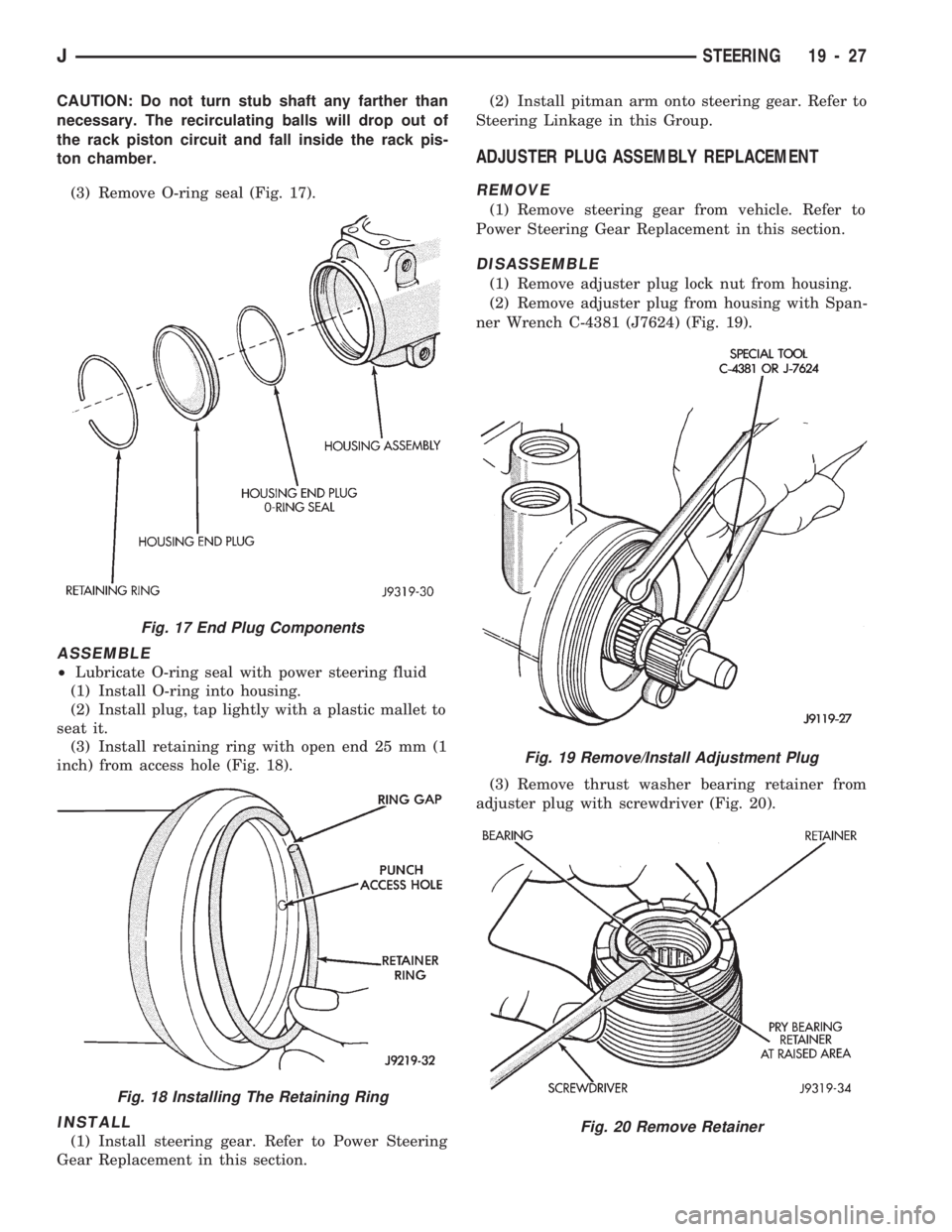
(3) Remove O-ring seal (Fig. 17).
ASSEMBLE
²Lubricate O-ring seal with power steering fluid
(1) Install O-ring into housing.
(2) Install plug, tap lightly with a plastic mallet to
seat it.
(3) Install retaining ring with open end 25 mm (1
inch) from access hole (Fig. 18).
INSTALL
(1) Install steering gear. Refer to Power Steering
Gear Replacement in this section.(2) Install pitman arm onto steering gear. Refer to
Steering Linkage in this Group.
ADJUSTER PLUG ASSEMBLY REPLACEMENT
REMOVE
(1) Remove steering gear from vehicle. Refer to
Power Steering Gear Replacement in this section.
DISASSEMBLE
(1) Remove adjuster plug lock nut from housing.
(2) Remove adjuster plug from housing with Span-
ner Wrench C-4381 (J7624) (Fig. 19).
(3) Remove thrust washer bearing retainer from
adjuster plug with screwdriver (Fig. 20).
Fig. 17 End Plug Components
Fig. 18 Installing The Retaining Ring
Fig. 19 Remove/Install Adjustment Plug
Fig. 20 Remove Retainer
JSTEERING 19 - 27
Page 1069 of 1784
turning the stub shaft COUNTERCLOCKWISE.
²The rack piston will be forced onto the tool and
hold the rack piston balls in place.
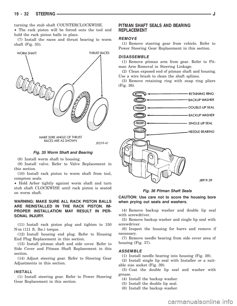
(7) Install the races and thrust bearing to worm
shaft (Fig. 35).
(8) Install worm shaft to housing.
(9) Install valve. Refer to Valve Replacement in
this section.
(10) Install rack piston to worm shaft from tool,
compress seals.
²Hold Arbor tightly against worm shaft and turn
stub shaft CLOCKWISE until rack piston is seated
on worm shaft.
WARNING: MAKE SURE ALL RACK PISTON BALLS
ARE REINSTALLED IN THE RACK PISTON. IM-
PROPER INSTALLATION MAY RESULT IN PER-
SONAL INJURY.
(11) Install rack piston plug and tighten to 150
Nzm (111 ft. lbs.) torque.
(12) Install housing end plug. Refer to Housing
End Plug Replacement in this section.
(13) Install pitman shaft and side cover. Refer to
Side Cover and Pitman Shaft Replacement in this
section.
(14) Adjust steering gear. Refer to Steering Gear
Adjustments in this section.
INSTALL
(1) Install steering gear. Refer to Power Steering
Gear Replacement in this section.
PITMAN SHAFT SEALS AND BEARING
REPLACEMENT
REMOVE
(1) Remove steering gear from vehicle. Refer to
Power Steering Gear Replacement in this section.
DISASSEMBLE
(1) Remove pitman arm from gear. Refer to Pit-
man Arm Removal in Steering Linkage.
(2) Clean exposed end of pitman shaft and housing.
Use a wire brush to clean the shaft splines.
(3) Remove retaining ring with snap ring pliers
(Fig. 36).
CAUTION: Use care not to score the housing bore
when prying out seals and washers.
(4) Remove backup washer and double lip seal
with screwdriver.
(5) Remove backup washer and single lip seal with
screwdriver.
(6) Inspect the housing for burrs and remove if
necessary.
(7) Remove needle bearing from side cover area of
housing (Fig. 37).
ASSEMBLE
(1) Install needle bearing into housing (Fig. 38).
(2) Install single lip seal with Installer or a suit-
able size socket (Fig. 39).
(3) Coat the double lip seal and washer with
grease.
(4) Install the backup washer.
(5) Install the double lip seal.
(6) Install the backup washer.
Fig. 36 Pitman Shaft Seals
Fig. 35 Worm Shaft and Bearing
19 - 32 STEERINGJ
Page 1280 of 1784
PRESSURE TEST ANALYSIS
If pressures in D and Reverse are higher than
specified, check for the following:
²throttle cable loose, worn, binding or out of adjust-
ment
²throttle valve, downshift plug, throttle cam, or pri-
mary regulator valve are sticking, worn or damaged
If pressures in D and Reverse are lower than spec-
ified, check for following:
²throttle cable loose, worn, binding or out of adjust-
ment
²throttle valve, downshift plug, throttle cam stick-
ing, worn or damaged
²primary regulator valve sticking, worn, or dam-
aged
²oil pump gears or housing worn or damaged
²overdrive clutch worn or damaged
If pressures are low in D range only, check for fol-
lowing:
²forward clutch worn or damaged
²fluid leakage in D range circuit (component seal
and O-rings)
If pressures are low in Reverse only, check for fol-
lowing:
²shift cable and manual valve out of adjustment
²fluid leakage in reverse circuit (component seal
and O-rings)
²direct clutch worn or damaged
²first/reverse brake worn or damaged
TORQUE CONVERTER STALL TEST
Stall testing checks the holding ability of the trans-
mission clutches and brakes and of the torque con-
verter stator overrunning clutch.
(1) Be sure transmission fluid is at normal operat-
ing temperature.
(2) Connect tachometer to engine. Position tachom-
eter so it can be viewed from drivers seat.
(3) Apply parking brakes and block wheels.
(4) Apply and hold service brakes.
(5) Shift transfer case into 2H position. On models
with NP249 transfer case, leave transfer case in 4H
position.
(6) Start engine.
WARNING: DO NOT ALLOW ANYONE TO STAND AT
THE FRONT OR REAR OF THE VEHICLE DURING
THE TEST.
(7) Shift transmission into D range.
(8) Press accelerator pedal to wide open throttle
position and note maximum engine rpm. Stall speed
should be 2100 to 2400 rpm in D range.
CAUTION: Do not maintain wide open throttle for
more than 3-4 seconds at a time.(9) Release throttle and shift transmission into
Neutral. Allow transmission fluid to cool for 15-20
seconds.
(10) Shift transmission into Reverse.
(11) Press accelerator down to wide open throttle
position and note maximum engine rpm. Stall speed
should be 2100-to-2400 rpm in Reverse.
STALL SPEED TEST ANALYSIS
If engine rpm is lower than specified in D and Re-
verse, check for the following:
²engine output/performance insufficient
²stator overrunning clutch in torque converter not
holding if engine speed was 1500 rpm or less.
If stall speed in D range is higher than specified,
check for the following:
²line pressure low
²forward clutch slipping
²No. 2 one-way clutch not holding
²overdrive one-way clutch not holding
If stall speed in Reverse was higher than specified,
check for the following:
²line pressure low
²direct clutch slipping
²first/ reverse brake slipping
²overdrive one-way clutch not holding
If stall speeds were higher than specified in both D
and Reverse, check for the following:
²low fluid level
²line pressure low
²overdrive one-way clutch not holding
TIME LAG TEST
This test checks general condition of the overdrive
clutch, forward clutch, rear clutch and first/reverse
brake. Condition is indicated by the amount of time
required for clutch/brake engagement with the en-
gine at curb idle speed. Engagement time is mea-
sured for D and Reverse positions. A stop watch is
recommended for test accuracy.
TEST PROCEDURE
(1) Check and adjust transmission fluid level if
necessary.
(2) Bring transmission to normal operating tem-
perature.
(3) Apply parking brakes and turn off air condi-
tioning unit.
(4) Shift transfer case into 2H range. On models
with NP249 transfer case, leave transfer case in 4H
range.
(5) Start engine and check curb idle speed. Adjust
speed if necessary. Curb idle must be correct to en-
sure accurate test results.
(6) Shift transmission into Neutral and set stop
watch.
(7) During following test steps, start stop watch as
soon as shift lever reaches D and Reverse ranges.
JAW-4 TRANSMISSION DIAGNOSIS 21 - 169
Page 1284 of 1784
AW-4 IN-VEHICLE SERVICE
INDEX
page page
Accumulator Pistons and Springs........... 179
Adapter Housing Seal Replacement.......... 182
Checking Fluid Level and Condition.......... 173
Manual Valve Shaft Seal Replacement....... 178
Park Interlock Cable Adjustment............ 186
Park Rod and Pawl Service................ 181
Park/Neutral Position Switch............... 173
Second Coast Brake Servo................ 181
Shift Cable Adjustment................... 186
Speed Sensor.......................... 182Speed Sensor RotorÐSpeedometer Drive Gear . 183
Throttle Position Sensor (TPS) Service....... 184
Transmission Control Module (TCM) Service . . . 173
Transmission Cooler Line Fittings........... 187
Transmission Cooler Service............... 187
Transmission Throttle Cable Adjustment....... 185
Transmission Throttle Cable Replacement..... 184
Transmission Valve Body Installation......... 177
Transmission Valve Body Removal.......... 176
Transmission Valve Body Solenoids.......... 175
CHECKING FLUID LEVEL AND CONDITION
Recommended fluid for AW-4 transmissions is Mo-
par Dexron IIE/Mercon. Mopar Dexron II may be
used if Mercon fluid is not readily available.
CHECKING FLUID LEVEL
(1) Be sure transmission fluid is at normal operat-
ing temperature. Normal operating temperature is
reached after approximately 15 miles (25 km) of op-
eration.
(2) Position vehicle on level surface. This is impor-
tant for an accurate fluid level check.
(3) Shift transmission through all gear ranges and
back to Park.
(4) Apply parking brakes.
(5) Verify that transmission is in Park.
(6) Wipe off dipstick handle to prevent dirt from
entering fill tube. Then remove dipstick and check
fluid level and condition.
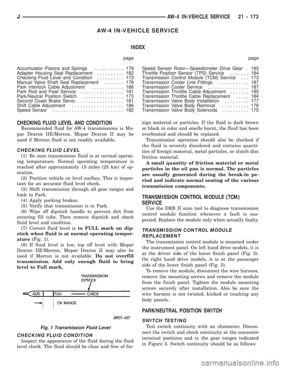
(7) Correct fluid level isto FULL mark on dip-
stick when fluid is at normal operating temper-
ature(Fig. 1).
(8) If fluid level is low, top off level with Mopar
Dexron IIE/Mercon. Mopar Dexron II may also be
used if Mercon is not available.Do not overfill
transmission. Add only enough fluid to bring
level to Full mark.
CHECKING FLUID CONDITION
Inspect the appearance of the fluid during the fluid
level check. The fluid should be clear and free of for-eign material or particles. If the fluid is dark brown
or black in color and smells burnt, the fluid has been
overheated and should be replaced.
Transmission operation should also be checked if
the fluid is severely discolored and contains quanti-
ties of foreign material, metal particles, or clutch disc
friction material.
A small quantity of friction material or metal
particles in the oil pan is normal. The particles
are usually generated during the break-in pe-
riod and indicate normal seating of the various
transmission components.
TRANSMISSION CONTROL MODULE (TCM)
SERVICE
Use the DRB II scan tool to diagnose transmission
control module function whenever a fault is sus-
pected. Replace the module only when actually faulty.
TRANSMISSION CONTROL MODULE
REPLACEMENT
The transmission control module is mounted under
the instrument panel. On left hand drive models, it is
at the driver side of the lower finish panel (Fig. 2).
On right hand drive models, it is at the passenger
side of the lower finish panel (Fig. 3).
To remove the module, disconnect the wire harness,
remove the mounting screws and remove the module
from the finish panel. Tighten the module mounting
screws securely after installation. Also be sure the
wire harness is not twisted, kinked or touching any
body panels.
PARK/NEUTRAL POSITION SWITCH
SWITCH TESTING
Test switch continuity with an ohmmeter. Discon-
nect the switch and check continuity at the connector
terminal positions and in the gear ranges indicated
in Figure 3. Switch continuity should be as follows:Fig. 1 Transmission Fluid Level
JAW-4 IN-VEHICLE SERVICE 21 - 173
Page 1650 of 1784
(3) If necessary, remove the retaining screws and
the hinge from the glove box door.
INSTALLATION
(1) If removed, install the hinge on the glove box
door with screws. Tighten the screws securely.
(2) Position the glove box door and hinge on the
glove box housing.
(3) Install the hinge-to-glove box housing screws
and adjust the door for proper fit within the opening.
Tighten the screws securely.
DOOR LATCH STRIKER ADJUSTMENT
The glove box door lock cylinder latch striker is at-
tached to the glove box housing opening with screws.
The striker can be moved in or out for adjustment.
SEATS
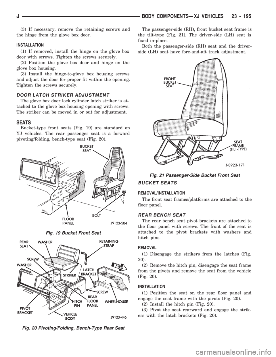
Bucket-type front seats (Fig. 19) are standard on
YJ vehicles. The rear passenger seat is a forward
pivoting/folding, bench-type seat (Fig. 20).The passenger-side (RH), front bucket seat frame is
the tilt-type (Fig. 21). The driver-side (LH) seat is
fixed in-place.
Both the passenger-side (RH) seat and the driver-
side (LH) seat have fore-and-aft track adjustment.
BUCKET SEATS
REMOVAL/INSTALLATION
The front seat frames/platforms are attached to the
floor panel.
REAR BENCH SEAT
The rear bench seat pivot brackets are attached to
the floor panel with screws. The front of the seat is
attached to the pivot brackets with washers and
hitch pins.
REMOVAL
(1) Disengage the strikers from the latches (Fig.
20).
(2) Remove the hitch pin, disengage the seat frame
from the pivots and remove the seat from the vehicle
(Fig. 20).
INSTALLATION
(1) Position the seat on the rear floor panel and
engage the seat frame with the pivots (Fig. 20).
(2) Install the hitch pin (Fig. 20).
(3) Pivot the seat rearward and engage the strik-
ers with the latch brackets (Fig. 20).
Fig. 19 Bucket Front Seat
Fig. 20 Pivoting/Folding, Bench-Type Rear Seat
Fig. 21 Passenger-Side Bucket Front Seat
JBODY COMPONENTSÐXJ VEHICLES 23 - 195
Page 1757 of 1784
INSTRUMENT PANEL ILLUMINATION
LAMPS............................8E-16
INSTRUMENT PANEL LAMPS..............8E-4
INSTRUMENT PANEL REPLACEMENT.......8E-8
INSTRUMENT PANEL SERVICE..........23-192
INSULATION PANEL, DASH PANEL........23-95
INSULATOR PANEL, DASH PANEL.........23-11
INSULATOR PANEL, HOOD..............23-138
INTAKE AIR TEMPERATURE SENSOR......14-54
INTAKE AIR TEMPERATURE SENSORÐ
PCM INPUT.........................14-20
INTAKE AIR TEMPERATURE SENSOR TEST . . . 14-43
INTAKE DUCT, FRESH AIR...............24-41
INTAKE MANIFOLD.....................14-57
INTAKE MANIFOLDÐ2.5L ENGINE..........11-8
INTAKE MANIFOLDÐ4.0L ENGINE..........11-9
INTAKE MANIFOLD AIR TEMPERATURE
SENSOR.......................8D-5,8D-27
INTAKE MANIFOLD AIR TEMPERATURE
SENSOR TEST.......................8D-14
INTAKE MANIFOLD LEAKAGE DIAGNOSIS.....9-5
INTERCHANGEABILITY, PARTS............21-66
INTERIOR COMPONENTS..........23-91,23-190
INTERIOR LAMPS......................8L-19
INTERIOR LAMPS, XJ..................8L-23
INTERIOR LAMPS, YJ..................8L-23
INTERIOR PAINT CODES, XJ............23-205
INTERIOR PAINT CODES, YJ............23-206
INTERIOR REARVIEW MIRROR...........23-74
INTERIOR REARVIEW MIRROR
SUPPORT BRACKET REPLACEMENT......23-75
INTERIOR TRIM PANELS AND SCUFF
PLATESÐXJ VEHICLES...............23-112
INTERLOCK CABLE ADJUSTMENT (XJ),
PARK........................21-97,21-186
INTERMEDIATE (COUPLING) SHAFT . . 19-21,19-43
INTERMITTENT WINDSHIELD WASHER,
DIAGNOSING........................8K-12
INTERMITTENT WIPER MODULE...........8K-5
INTERMITTENT WIPER WASHER..........8K-20
INTERNATIONAL VEHICLE CONTROL
AND DISPLAY SYMBOLS............INTRO.-3
IN-VEHICLE SERVICE, 30RH/32RH.........21-96
IN-VEHICLE SERVICE, AW-4.............21-173
ISOLATION, COMPRESSOR..............24-17
JACK STORAGEÐXJ VEHICLES..........23-127
JOINT ANGLE MEASUREMENT,
UNIVERSAL..........................16-4
JOINT REPLACEMENT, UNIVERSAL.........16-9
JOINTS, UNIVERSAL....................16-2
JOUNCE BUMPER, REAR................13-18
JUMP STARTING........................0-7
JUMP STARTING, HOISTING AND TOWING.....0-7
KEY LOCK CYLINDER, DOOR.............23-54
KEY LOCK CYLINDER, FULL-METAL
DOOR............................23-178
KEY LOCK CYLINDERS.............23-2,23-132
KEY WARNING SWITCH REPLACEMENT,
IGNITION............................8U-4
KEYLESS ENTRY.......................8P-8
KNOCK, LOW SPEED; FRONT
SUSPENSION AND AXLE................2-17
KNOCK, LOW SPEED; REAR SUSPENSION
AND AXLES...........................3-8
KNUCKLE AND BALL STUDS, STEERING.....2-30
LABEL, TIRE INFLATION PRESSURE.....INTRO.-3
LABEL, VEHICLE EMISSION CONTROL
INFORMATION (VECI)
..................25-1
LABEL, VEHICLE SAFETY CERTIFICATION
. INTRO.-1
LABELS/DECALS/PLATES
...........23-1,23-132
LABELS/PLATES, CODES AND
DIMENSIONS, DESIGNATIONS,
.......INTRO.-1
LAG TEST, TIME
......................21-169
LAMP, 4WD INDICATOR
..................8E-2
LAMP, ANTI-LOCK BRAKE SYSTEM (ABS)
INDICATOR
..........................8E-2
LAMP BEAM ADJUSTMENT, FOG
..........8L-12
LAMP, BRAKE INDICATOR; INSTRUMENT
PANEL AND GAUGESÐXJ
...............8E-2
LAMP, BRAKE INDICATOR; INSTRUMENT
PANEL AND GAUGESÐYJ
..............8E-16
LAMP BULB REPLACEMENT, BACK-UP/
REAR TURN SIGNAL/TAIL
...............8L-9
LAMP BULB REPLACEMENT, FRONT PARK/
TURN SIGNAL
........................8L-8LAMP BULB REPLACEMENT, SIDE
MARKER............................8L-7
LAMP BULB REPLACEMENT,
UNDERHOOD........................8L-18
LAMP BULB REPLACEMENTÐYJ
VEHICLES, HARDTOP DOME/CARGO.....8L-20
LAMP BULB/ELEMENT REPLACEMENT,
FOG ...............................8L-13
LAMP (CHECK ENGINE), MALFUNCTION
INDICATOR; INSTRUMENT PANEL
AND GAUGESÐXJ................8E-2,8E-4
LAMP (CHECK ENGINE), MALFUNCTION
INDICATOR; INSTRUMENT PANEL
AND GAUGESÐYJ...................8E-16
LAMP (CHMSL)ÐXJ, CENTER HIGH
MOUNTED STOP.....................8L-10
LAMP (CHMSL)ÐYJ, CENTER HIGH
MOUNTED STOP.....................8L-11
LAMP, COOLANT TEMPERATURE
INDICATOR..........................8E-1
LAMP FOR DIAGNOSTIC TROUBLE CODES,
INDICATOR (CHECK ENGINE)...........8A-19
LAMP HOUSING, LIFTGATE LICENSE
PLATE .............................23-72
LAMP, I/P ASH RECEIVER TRAY..........23-92
LAMP, LICENSE PLATE..................8L-10
LAMP, LOW FUEL WARNING..............8E-2
LAMPÐPCM OUTPUT, EMR..............14-24
LAMPÐPCM OUTPUT, GENERATOR.......14-25
LAMPÐPCM OUTPUT, MALFUNCTION
INDICATOR.........................14-26
LAMP REPLACEMENT, DOME.............8L-20
LAMP REPLACEMENT, FOG..............8L-15
LAMP REPLACEMENT, UNDERHOOD.......8L-18
LAMP, SEAT BELT REMINDER............8E-16
LAMP SERVICE INFORMATION, DOME/
COURTESY.........................8L-19
LAMP SERVICE INFORMATION, FOG.......8L-12
LAMP SERVICE INFORMATION,
UNDERHOOD........................8L-17
LAMP, SERVICE REMINDER INDICATOR
(SRI)...............................25-1
LAMP SPEED CONTROL SWITCH TEST,
STOP...............................8H-7
LAMP SUPPORT BRACKET, I/P TWEETER
SPEAKER/COURTESY.................23-95
LAMP SWITCH REPLACEMENT, FOG.......8L-14
LAMP TROUBLE DIAGNOSIS, DOME/
COURTESY.........................8L-19
LAMP TROUBLE DIAGNOSIS, FOG.........8L-12
LAMP, UPSHIFT INDICATOR;
INSTRUMENT PANELAND GAUGESÐXJ....8E-2
LAMP, UPSHIFT INDICATOR;
INSTRUMENT PANELAND GAUGESÐYJ . . . 8E-16
LAMPÐYJ RENEGADE VEHICLES, FOG....23-150
LAMP/REAR WIPER SWITCHES, REAR
DEFOGGER/FOG......................8E-21
LAMPS, EXTERIOR......................8L-1
LAMPS, INDICATOR....................8E-14
LAMPS INOPERATIVE, DIAGNOSISÐ
HAZARD.........................8J-1,8J-2
LAMPS, INSTRUMENT PANEL.............8E-4
LAMPS, INSTRUMENT PANEL
ILLUMINATION......................8E-16
LAMPS, INTERIOR.....................8L-19
LAMPS OUT, DIAGNOSINGÐALL..........8E-16
LAMPS, XJ EXTERIOR..................8L-23
LAMPSÐXJ, HAZARD...................8J-1
LAMPS, XJ INTERIOR..................8L-23
LAMPS, YJ EXTERIOR..................8L-23
LAMPSÐYJ, HAZARD...................8J-2
LAMPS, YJ INTERIOR..................8L-23
LATCH ADJUSTMENT, DOOR.............23-55
LATCH AND RELEASE HANDLE,
TAILGATE..........................23-160
LATCH ASSEMBLY REPLACEMENT,
SOLENOID...........................8P-6
LATCH, DOOR.........................23-56
LATCH EXTERNAL RELEASE HANDLE,
FULL-METAL DOOR..................23-178
LATCH, FULL-METAL DOOR
.............23-179
LATCH, HOOD SAFETY
.................23-139
LATCH INSIDE RELEASE AND LOCK
HANDLE, FULL-METAL DOOR
..........23-175
LATCH RELEASE AND LOCK RODS,
DOOR INSIDE
.......................23-57LATCH RELEASE CABLE REPLACEMENT....23-10
LATCH REPLACEMENT, HOOD............23-10
LATCH STRIKER AND BUMPERÐXJ
VEHICLES, REAR SEATBACK...........23-111
LATCH STRIKER, HALF-METAL DOOR.....23-175
LATCH STRIKER REPLACEMENT, HOOD....23-10
LATCH STRIKER REPLACEMENT, SAFETY . . . 23-10
LATCH STRIKER, TAILGATE.............23-161
LATCH/KEY LOCK CYLINDER/STRIKER,
LIFTGATE...........................23-68
LEAD CORRECTION CHART...............22-5
LEAF SPRING; FRONT SUSPENSION AND
AXLE...............................2-14
LEAF SPRING; REAR SUSPENSION AND
AXLES............................3-3,3-6
LEAF SPRING EYE BUSHING
REPLACEMENT; FRONT SUSPENSION
AND AXLE...........................2-15
LEAF SPRING EYE BUSHING
REPLACEMENT; REAR SUSPENSION
AND AXLES........................3-4,3-6
LEAK DETECTION AND REPAIR, FIXED
GLASS WATER................23-83,23-189
LEAK DIAGNOSIS, CONVERTER HOUSING . . . 21-73
LEAK DOWN TEST, FUEL PRESSURE........14-7
LEAK TEST, REFRIGERANT................24-8
LEAKAGE DIAGNOSIS, GEAR
..............19-8
LEAKAGE DIAGNOSIS, INTAKE
MANIFOLD
............................9-5
LEAKAGE DIAGNOSIS, PUMP
..............19-8
LEAKAGE TEST, CYLINDER COMBUSTION
PRESSURE
...........................9-6
LEAKAGE TEST DIAGNOSIS, CYLINDER
COMBUSTION PRESSURE
................9-6
LEAKS, REPAIRING
.....................22-3
LEAKS, TESTING COOLING SYSTEM FOR
....7-18
LEFT HAND DRIVE, DRIVERS DOOR
POWER LOCK SWITCHÐ2-DOOR
.........8P-2
LEFT HAND DRIVE, DRIVERS DOOR
POWER WINDOW SWITCHÐ2-DOOR
......8S-6
LETTERS, JEEP BODY CODE
...............5-2
LEVEL AND CONDITION, CHECKING
FLUID
.......................21-96,21-173
LEVEL AND CONDITION, FLUID
...........21-69
LEVEL, BRAKE FLUID
....................5-13
LEVELÐBRAKELINES AND HOSES,
BRAKE BLEEDINGÐBRAKE FLUID
........5-13
LEVEL, CLUTCH FLUID
...................6-14
LEVEL, COMPRESSOR OIL
................24-6
LEVEL, CORRECT FLUID
.................5-48
LEVEL, TRANSFER CASE FILL
...........21-294
LEVELS, OPERATING SOUND
...............5-3
LEVER INSTALLATION (XJ WITH FULL
CONSOLE), PARKING BRAKE
............5-60
LEVER INSTALLATION (XJ WITH MINI
CONSOLE), PARKING BRAKE
............5-58
LEVER INSTALLATION (XJ WITHOUT
CONSOLE), PARKING BRAKE
............5-60
LEVER POSITIONS, TRANSMISSION
RANGES AND SHIFT
.................21-157
LEVER REMOVAL (XJ WITH FULL
CONSOLE), PARKING BRAKE
............5-59
LEVER REMOVAL (XJ WITH MINI
CONSOLE), PARKING BRAKE
............5-58
LEVER REMOVAL (XJ WITHOUT
CONSOLE), PARKING BRAKE
............5-60
LICENSE PLATE LAMP
..................8L-10
LICENSE PLATE LAMP HOUSING,
LIFTGATE
...........................23-72
LICENSE PLATE SCREW ANCHOR
AND BUMPER, LIFTGATE
..............23-72
LIFTGATE ADJUSTMENT
.................23-70
LIFTGATE GLASS, HARD TOP
............23-162
LIFTGATE GLASS WEATHERSTRIP SEAL
REPLACEMENT
.....................23-163
LIFTGATE HINGE
.......................23-67
LIFTGATE LATCH/KEY LOCK CYLINDER/
STRIKER
...........................23-68
LIFTGATE LICENSE PLATE LAMP
HOUSING
...........................23-72
LIFTGATE LICENSE PLATE SCREW
ANCHOR AND BUMPER
...............23-72
JINDEX13
Description Group-Page Description Group-Page Description Group-Page
Page 1761 of 1784
PITMAN SHAFT SEALSÐIN CAR
REPLACEMENT......................19-21
PIVOT ASSEMBLY REPLACEMENT, FRONT
WIPER ARM.........................8K-9
PLANETARY GEAR AND CLUTCH
OVERHAUL, OVERDRIVE..............21-209
PLANETARY GEAR OVERHAUL, FRONT....21-228
PLANETARY GEAR TRAIN OVERHAUL.....21-131
PLASTIC COMPONENTS................23-203
PLASTIC DUCTS/HOSES/TUBING, RUBBER . . . 0-19
PLASTIC HOSES/TUBING, RUBBER.........0-28
PLASTIC INSERT ÐXJ VEHICLES, QUARTER
WINDOW GLASS/REAR QUARTER.......23-80
PLASTIGAGE, MEASURING WITH...........9-3
PLATE, FRONT SKID....................23-84
PLATE, FUEL TANK SKID; BODY
COMPONENTSÐXJ VEHICLES..........23-84
PLATE, FUEL TANK SKID; FRAME AND
BUMPERS..........................13-16
PLATE LAMP HOUSING, LIFTGATE
LICENSE...........................23-72
PLATE LAMP, LICENSE..................8L-10
PLATEÐLEAK TESTS, COMPRESSOR
VALVE ..............................24-8
PLATE REPLACEMENT, SUPPORT..........5-37
PLATE SCREW ANCHOR AND BUMPER,
LIFTGATE LICENSE...................23-72
PLATE SERVICE, DRIVE................21-109
PLATE SPECIFICATIONS, 30RH/32RH SNAP
RING/THRUST WASHER/THRUST.......21-322
PLATE THICKNESS, AW-4 CLUTCH DISC . . . 21-325
PLATE, TRANSFER CASE SKID; BODY
COMPONENTSÐXJ VEHICLES.....13-15,23-84
PLATE, VEHICLE CODE...............INTRO.-2
PLATE, VEHICLE IDENTIFICATION
NUMBER (VIN)....................INTRO.-1
PLATEÐYJ RENEGADE VEHICLES, FRONT
FASCIA AND SKID...................23-148
PLATEÐYJ RENEGADE VEHICLES, REAR
FASCIA AND SKID...................23-152
PLATE/COWL SIDE TRIM PANELÐXJ
VEHICLES, FRONT INNER SCUFF.......23-114
PLATESÐXJ VEHICLES, INTERIOR TRIM
PANELS AND SCUFF.................23-112
PLATESÐXJ VEHICLES, OUTER SCUFF....23-118
PLATFORM AND TRACKS, BUCKET SEAT . . . 23-105
PLUG ASSEMBLY REPLACEMENT,
ADJUSTER..........................19-27
PLUG CABLE RESISTANCE, SPARK........8D-18
PLUG, HOUSING END...................19-26
PLUG LOCATIONS, TRANSMISSION
SWITCH............................21-33
PLUG SECONDARY CABLES, SPARK . . 8D-17,8D-29
PLUGS, SPARK; IGNITION SYSTEMS . 8D-16,8D-28,
8D-33
PLUGS, SPARK; LUBRICATION AND
MAINTENANCE.......................0-18
POLISHING, BUFFING..................23-203
POSITION, HYDRAULIC FLOW IN MANUAL
FIRST GEAR (1)......................21-94
POSITION SENSOR, CAMSHAFT; FUEL
SYSTEM............................14-54
POSITION SENSOR, CAMSHAFT;
IGNITION SYSTEMS..............8D-1,8D-20
POSITION SENSOR, CRANKSHAFT; FUEL
SYSTEM............................14-55
POSITION SENSOR, CRANKSHAFT;
IGNITION SYSTEMS..............8D-2,8D-21
POSITION SENSORÐPCM INPUT,
CAMSHAFT.........................14-20
POSITION SENSORÐPCM INPUT,
CRANKSHAFT.......................14-20
POSITION SENSOR TEST, CAMSHAFT;
FUEL SYSTEM.......................14-43
POSITION SENSOR TEST, CAMSHAFT;
IGNITION SYSTEMS...................8D-8
POSITION SENSOR TEST, CRANKSHAFT;
FUEL SYSTEM.......................14-44
POSITION SENSOR TEST, CRANKSHAFT;
IGNITION SYSTEMS...................8D-9
POSITION SENSOR TEST, THROTTLE
......8D-18
POSITION SENSOR, THROTTLE
............8D-6
POSITION SENSOR (TPS)ÐPCM INPUT,
THROTTLE
..........................14-23
POSITION SENSOR (TPS) SERVICE,
THROTTLE
.........................21-184POSITION SENSOR (TPS) TEST, THROTTLE . 14-45
POSITION SENSOR (TPS), THROTTLE;
FUEL SYSTEM.......................14-59
POSITION SENSOR (TPS), THROTTLE;
IGNITION SYSTEMS..................8D-29
POSITION SWITCH, PARK/NEUTRAL;
BATTERY/STARTER/GENERATOR SERVICE . . 8B-6
POSITION SWITCH, PARK/NEUTRAL;
TRANSMISSION AND TRANSFER CASE . . 21-173
POSITION SWITCH SERVICE, PARK/
NEUTRAL..........................21-103
POSITION, SWITCH TEST WITH SWITCH IN
LEFT................................8T-3
POSITION, SWITCH TEST WITH SWITCH
IN RIGHT............................8T-3
POSITIONS, TRANSMISSION RANGES
AND SHIFT LEVER...................21-157
POWER BOOSTER CHECK VALVE TEST......5-11
POWER BOOSTER VACUUM TEST..........5-12
POWER BRAKE BOOSTER............5-22,5-40
POWER BRAKE BOOSTER INSTALLATION . . . 5-23,
5-51
POWER BRAKE BOOSTER OPERATION......5-22
POWER BRAKE BOOSTER REMOVAL....5-22,5-51
POWER BRAKE SYSTEM.................0-32
POWER BRAKES........................5-1
POWER BUCKET SEAT COMPONENTS.....23-106
POWER DOOR LOCKS..............8P-1,8P-10
POWER DOOR LOCKS, DIAGNOSING . . . 8P-1,8P-9
POWER GROUND......................14-22
POWER LOCK SWITCHÐ2-DOOR LEFT
HAND DRIVE, DRIVERS DOOR...........8P-2
POWER LOCK SWITCHÐ2-DOOR RIGHT
HAND DRIVE, DRIVERS DOOR...........8P-3
POWER LOCK SWITCHÐ4-DOOR,
DRIVERS DOOR......................8P-4
POWER MIRROR REPLACEMENT...........8T-4
POWER MIRROR SWITCH................8T-2
POWER MIRROR SWITCH REPLACEMENT....8T-4
POWER MIRROR SWITCH TESTING.........8T-2
POWER SEAT MOTOR REPLACEMENT......8R-2
POWER STEERING GEAR................19-73
POWER STEERING GEAR,
RECIRCULATING BALL................19-19
POWER STEERING GEAR SPECIFICATIONS . . . 19-34
POWER STEERING GEARS,
RECIRCULATING-BALL................19-69
POWER STEERING PRESSURE SWITCHÐ
2.5L ENGINE ONLY...................14-58
POWER STEERING PRESSURE SWITCHÐ
PCM INPUT.........................14-22
POWER STEERING PUMP......19-9,19-69,19-73
POWER STEERING PUMPÐINITIAL
OPERATION.........................19-13
POWER STEERING SYSTEM..............0-31
POWER STEERING SYSTEM DIAGNOSIS....19-3,
19-4,19-5,19-6,19-7
POWER WINDOW SWITCHÐ2-DOOR
LEFT HAND DRIVE, DRIVERS DOOR.......8S-6
POWER WINDOW SWITCHÐ2-DOOR
RIGHT HAND DRIVE, DRIVERS DOOR.....8S-7
POWER WINDOW SWITCHÐ4-DOOR,
DRIVERS DOOR......................8S-5
POWERTRAIN CONTROL MODULE (PCM)
60-WAY CONNECTOR.................14-38
POWERTRAIN CONTROL MODULE,
ELECTRICAL TESTS AT.................8H-6
POWERTRAIN CONTROL MODULE
(PCM); EMISSION CONTROL SYSTEMS....25-9
POWERTRAIN CONTROL MODULE
(PCM); FUEL SYSTEM............14-18,14-58
POWERTRAIN CONTROL MODULE
(PCM); IGNITION SYSTEMS
. . . 8D-6,8D-15,8D-28
POWER-UP AND INITIALIZATION, SYSTEM
. . . 5-43
PRE-ALIGNMENT INSPECTION
..............2-6
PRECAUTIONS, BRAKE SAFETY
.............5-2
PRECAUTIONS, CLUTCH SAFETY
...........6-10
PRECAUTIONS; PROPELLER SHAFTS
. . . 16-7,16-9
PRECAUTIONS, SAFETY, REFINISHING
.....23-200
PRECAUTIONS, SERVICE (A/C)
............24-2
PRELIMINARY BRAKE CHECK
..............5-7
PRELIMINARY CHECKS
...................7-5
PRELIMINARY CHECKS FIRST, SYMPTOM
AND ACTIONÐSEE
.....................7-6
PRELIMINARY DIAGNOSIS
...............21-69PRELIMINARY INSPECTION AND
ADJUSTMENT......................21-167
PREPARATION, SURFACE...............23-201
PRESSURE AND RETURN HOSE
REPLACEMENT.......................19-9
PRESSURE CAP, RADIATOR...............7-20
PRESSURE DIAGNOSIS..................24-9
PRESSURE GAUGE AND MANIFOLD
ASSEMBLY..........................24-2
PRESSURE GAUGE INOPERATIVE, OIL......8E-3
PRESSURE GAUGE, OIL..................8E-1
PRESSURE GAUGES.....................22-2
PRESSURE INDICATOR INOPERATIVE, OIL . . . 8E-3
PRESSURE INDICATOR, OIL...............8E-1
PRESSURE LABEL, TIRE INFLATION.....INTRO.-3
PRESSURE LEAK DOWN TEST, FUEL........14-7
PRESSURE LEAKAGE TEST, CYLINDER
COMBUSTION.........................9-6
PRESSURE LEAKAGE TEST DIAGNOSIS,
CYLINDER COMBUSTION................9-6
PRESSURE (MAP) SENSOR, MANIFOLD
ABSOLUTE; FUEL SYSTEM.............14-57
PRESSURE (MAP) SENSOR, MANIFOLD
ABSOLUTE; IGNITION SYSTEMS....8D-5,8D-27
PRESSURE (MAP) SENSORÐPCM
INPUT, MANIFOLD ABSOLUTE...........14-21
PRESSURE (MAP) SENSOR TEST,
MANIFOLD ABSOLUTE; FUEL SYSTEM....14-44
PRESSURE (MAP) SENSOR TEST, MANIFOLD
ABSOLUTE; IGNITION SYSTEMS........8D-14
PRESSURE REGULATOR, FUEL...........14-30
PRESSURE RELEASE PROCEDURE, FUEL....14-5
PRESSURE RELEASE PROCEDURE, FUEL
SYSTEM............................14-56
PRESSURE RELIEF/ROLLOVER VALVE . . . 25-5,25-9
PRESSURE RELIEF/ROLLOVER VALVE,
FUEL TANK....................14-15,14-56
PRESSURE SWITCHÐ2.5L ENGINE ONLY,
POWER STEERING...................14-58
PRESSURE SWITCHÐPCM INPUT,
POWER STEERING...................14-22
PRESSURE TEST, AIR...................21-73
PRESSURE TEST, CYLINDER COMPRESSION . . 9-5
PRESSURE TEST, FUEL SYSTEM......14-5,14-48
PRESSURE TEST, HYDRAULIC......21-71,21-168
PRESSURE TEST, PUMP.................19-3
PRESSURE TEST SPECIFICATIONS,
30RH/32RH........................21-323
PRESSURES, TIRE INFLATION.............22-2
PRIMER............................23-201
PRINTED CIRCUIT.....................8E-22
PRINTED CIRCUIT REMOVAL.............8E-24
PRINTED CIRCUIT REPLACEMENT.........8E-19
PRINTED CIRCUIT REPLACEMENTÐ
INSTRUMENT CLUSTER REMOVED.......8E-6
PROBLEM CAUSES, CLUTCH...............6-3
PROBLEMS, DIAGNOSING PARKING BRAKE . . 5-10
PROBLEMS, DIAGNOSING SERVICE BRAKE . . . 5-8
PROBLEMS, TROUBLESHOOTING WIRING . . . 8W-3
PROGRAMMING, TRANSMITTER...........8P-9
PROPELLER SHAFT REPLACEMENT.........16-7
PROPELLER SHAFTS....................16-1
PROPELLER SHAFTS AND U-JOINTS.......16-14
PROTECTION, STONE CHIP.............23-201
PROTECTOR STRIP, DOOR EDGE GUARD/
EDGE..............................23-61
PROTECTOR/NOZZLE, FUEL FILLER.......23-158
PULLEY REPLACEMENT, DRIVE...........19-11
PUMP AND PEDAL TRAVEL SENSOR
OPERATION, HCU.....................5-44
PUMP CAPACITY TEST, FUEL..............14-7
PUMP ELECTRICAL CONTROL, FUEL........14-5
PUMPÐINITIAL OPERATION, POWER
STEERING
..........................19-13
PUMP LEAKAGE DIAGNOSIS
..............19-8
PUMP MODULE, FUEL
..............14-2,14-56
PUMP, OIL
........................9-33,9-73
PUMP OPERATING SPECIFICATIONS
........19-3
PUMP OVERHAUL, OIL
..........21-122,21-206
PUMP, POWER STEERING
......19-9,19-69,19-73
PUMP PRESSURE TEST
..................19-3
PUMP RELAY, FUEL
....................14-56
PUMP RELAYÐPCM OUTPUT, FUEL
.......14-25
PUMP RELAY TESTING, FUEL
............14-44
PUMP REPLACEMENT
..................19-10
JINDEX17
Description Group-Page Description Group-Page Description Group-Page