1994 JEEP CHEROKEE automatic transmission fluid
[x] Cancel search: automatic transmission fluidPage 3 of 1784
ROUTINE SERVICE
The following routine vehicle service is highly rec-
ommended on a monthly basis.
TIRESÐInspect the tires for unusual wear/damage
and determine if the inflation pressure is acceptable
for the vehicle load.
BATTERYÐInspect and clean the terminals.
Tighten the terminals, if necessary.
FLUIDSÐDetermine if the coolant, brake fluid,
power steering, automatic transmission, and clutch
fluid level are acceptable. Add fluid, if necessary.
LIGHTS/ELECTRICALÐTest all the electrically
operated systems in the vehicle for proper operation.
It is also recommended that the engine oil level
and the windshield washer fluid level be deter-
mined (and corrected) during each fuel fill-up.
FUEL REQUIREMENTS
All Jeeptengines require the use of unleaded gas-
oline. In addition, the fuel must have a minimum oc-
tane rating of 87.
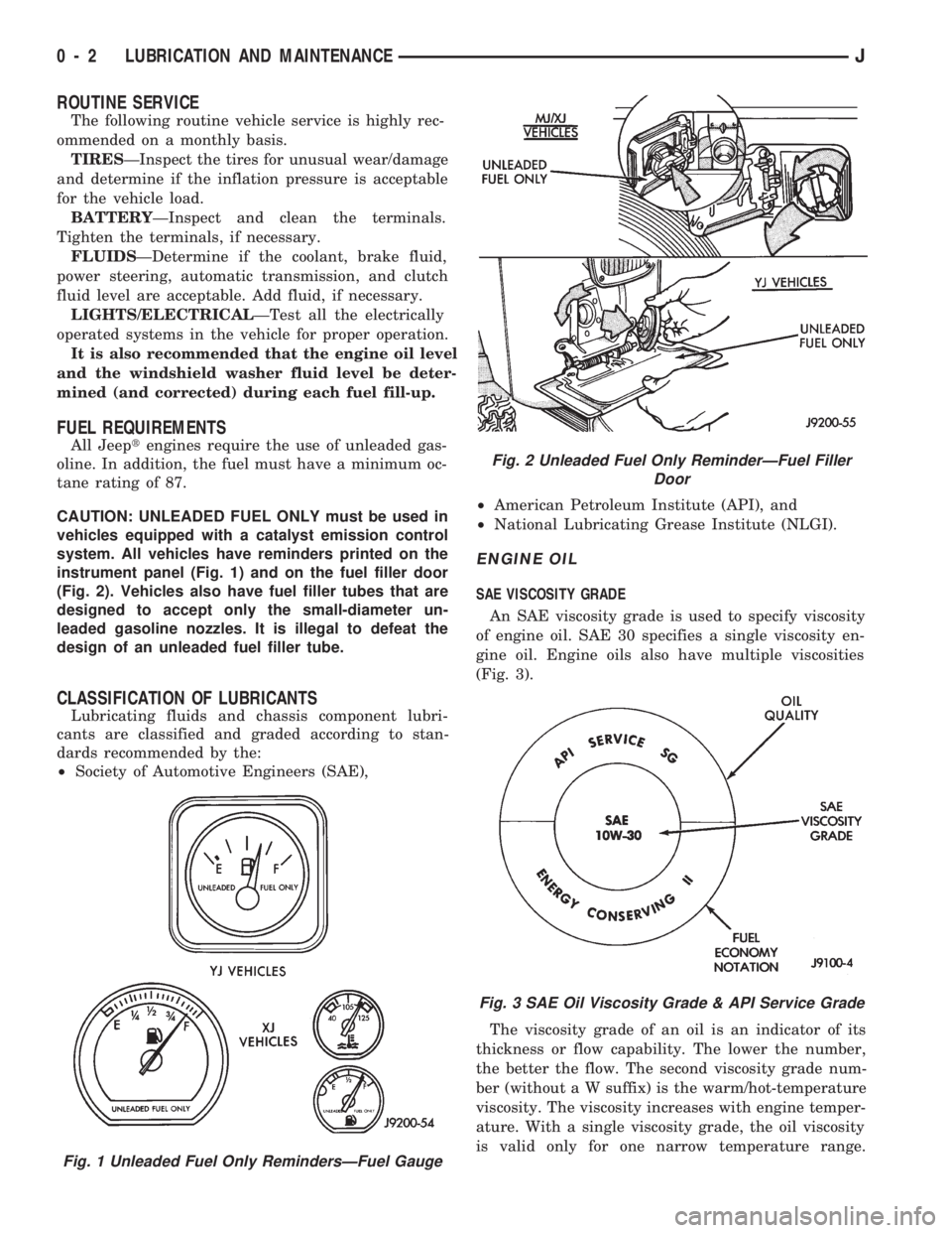
CAUTION: UNLEADED FUEL ONLY must be used in
vehicles equipped with a catalyst emission control
system. All vehicles have reminders printed on the
instrument panel (Fig. 1) and on the fuel filler door
(Fig. 2). Vehicles also have fuel filler tubes that are
designed to accept only the small-diameter un-
leaded gasoline nozzles. It is illegal to defeat the
design of an unleaded fuel filler tube.
CLASSIFICATION OF LUBRICANTS
Lubricating fluids and chassis component lubri-
cants are classified and graded according to stan-
dards recommended by the:
²Society of Automotive Engineers (SAE),²American Petroleum Institute (API), and
²National Lubricating Grease Institute (NLGI).
ENGINE OIL
SAE VISCOSITY GRADE
An SAE viscosity grade is used to specify viscosity
of engine oil. SAE 30 specifies a single viscosity en-
gine oil. Engine oils also have multiple viscosities
(Fig. 3).
The viscosity grade of an oil is an indicator of its
thickness or flow capability. The lower the number,
the better the flow. The second viscosity grade num-
ber (without a W suffix) is the warm/hot-temperature
viscosity. The viscosity increases with engine temper-
ature. With a single viscosity grade, the oil viscosity
is valid only for one narrow temperature range.
Fig. 1 Unleaded Fuel Only RemindersÐFuel Gauge
Fig. 2 Unleaded Fuel Only ReminderÐFuel Filler
Door
Fig. 3 SAE Oil Viscosity Grade & API Service Grade
0 - 2 LUBRICATION AND MAINTENANCEJ
Page 6 of 1784

MAINTENANCE SCHEDULES
INTRODUCTION
Chrysler Corporation has compiled recommended
lubrication and maintenance schedules and proce-
dures to help reduce premature wear or failure over
a broad range of operating conditions.
SEVERE SERVICE MAINTENANCE
If the vehicle is involved with a severe driving con-
dition, after each 4 800-km (3,000-miles)/3-month in-
terval. A severe driving condition includes:
²frequent short trip driving less than 24 km (15
miles);
²frequent driving in a dusty environment;
²trailer towing;
²extensive engine idling;
²sustained high-speed operation;
²desert operation;
²frequent starting and stopping;
²cold-climate operation;
²off-road driving; or
²commercial service.
MAINTENANCE SCHEDULES
AT EACH STOP FOR FUEL
²Check engine oil level, add as required.
²
Check windshield washer solvent and add if required.
ONCE A MONTH
²Check tire pressure and look for unusual wear or
damage.
²Inspect battery and clean and tighten terminals as
required.
²Check electrolyte level and add water as needed.
²Check fluid levels of coolant reservoir, power steer-
ing and transmission and add as needed.
²Check all lights and all other electrical items for
correct operation.
²Check rubber seals on each side of the radiator for
proper fit.
7,500 MILES (12 000 KM) OR AT 6 MONTHS
²Check engine coolant level, hoses and clamps.
²Change engine oil.
²Replace engine oil filter.
²Check exhaust system.
²Lubricate steering linkage (4x4 models).
²Lubricate propeller shaft universal joints.
²Rotate Tires.
15,000 MILES (24 000 KM) OR AT 12 MONTHS
²Check engine coolant level, hoses and clamps.
²Change engine oil.
²Replace engine oil filter.
²Check exhaust system.
²Lubricate steering linkage (4x4 models).
²Lubricate propeller shaft universal joints.²Check fluid level in battery.
²Rotate Tires.
22,500 MILES (36 000 KM) OR AT 18 MONTHS
²Check engine coolant level, hoses and clamps.
²Change engine oil.
²Replace engine oil filter.
²Check exhaust system.
²Lubricate steering linkage (4x4 models).
²Lubricate propeller shaft universal joints.
²Rotate Tires.
30,000 MILES (48 000 KM) OR AT 24 MONTHS
²Replace air cleaner filter.
²Replace spark plugs.
²Adjust drive belt.
²Check engine coolant level, hoses and clamps.
²Change engine oil.
²Replace engine oil filter.
²Check exhaust system.
²Lubricate steering linkage (4x4 models).
²Lubricate propeller shaft universal joints.
²Check fluid level in battery.
²Drain and refill automatic transmission.
²Drain and refill transfer case.
²Rotate Tires.
37,500 MILES (60 000 KM) OR AT 30 MONTHS
²Check engine coolant level, hoses and clamps.
²Change engine oil.
²Replace engine oil filter.
²Check exhaust system.
²Lubricate steering linkage (4x4 models).
²Lubricate propeller shaft universal joints.
²Drain and refill manual transmission.
²Rotate Tires.
45,000 MILES (72 500 KM) OR AT 36 MONTHS
²Check engine coolant level, hoses and clamps.
²Change engine oil.
²Replace engine oil filter.
²Check exhaust system.
²Lubricate steering linkage (4x4 models).
²Lubricate propeller shaft universal joints.
²Check fluid level in battery.
²Rotate Tires.
52,500 MILES (84 500 KM) OR AT 42 MONTHS
²Flush and replace engine coolant.
²Check engine coolant system hoses and clamps.
²Change engine oil.
²Replace engine oil filter.
²Check exhaust system.
²Lubricate steering linkage (4x4 models).
²Lubricate propeller shaft universal joints.
²Rotate Tires.
JLUBRICATION AND MAINTENANCE 0 - 5
Page 7 of 1784

60,000 MILES (96 500 KM) OR AT 48 MONTHS.
²Replace air cleaner filter.
²Replace distributor cap and rotor.
²Replace ignition wires.
²Replace spark plugs.
²Adjust or replace drive belt.
²Check engine coolant level, hoses and clamps.
²Change engine oil.
²Replace engine oil filter.
²Check exhaust system.
²Replace fuel filter (not required for Calif. vehicles).
²Lubricate steering linkage (4x4 models).
²Lubricate propeller shaft universal joints.
²Check fluid level in battery.
²Drain and refill automatic transmission.
²Drain and refill transfer case.
²Rotate Tires.
67,500 MILES (108 500 KM) OR AT 54
MONTHS
²Check engine coolant level, hoses and clamps.
²Change engine oil.
²Replace engine oil filter.
²Check exhaust system.
²Lubricate steering linkage (4x4 models).
²Lubricate propeller shaft universal joints.
²Rotate Tires.
75,000 MILES (120 500 KM) OR AT 60
MONTHS
²Check engine coolant level, hoses and clamps.
²Change engine oil.
²Replace engine oil filter.
²Check exhaust system.
²Lubricate steering linkage (4x4 models).
²Lubricate propeller shaft universal joints.
²Drain and refill manual transmission.
²Rotate Tires.
82,500 MILES (133 000 KM) OR AT 66
MONTHS
²Flush and replace engine coolant.
²Check engine coolant system, hoses and clamps.
²Change engine oil.
²Replace engine oil filter.
²Check exhaust system.
²Lubricate steering linkage (4x4 models).
²Lubricate propeller shaft universal joints.
²Rotate Tires.
90,000 MILES (145 000 KM) OR AT 72
MONTHS
²Replace air cleaner filter.
²Replace spark plugs.
²Adjust drive belt.
²Check engine coolant level, hoses and clamps.
²Change engine oil.
²Replace engine oil filter.²Check exhaust system.
²Lubricate steering linkage (4x4 models).
²Lubricate propeller shaft universal joints.
²Check fluid level in battery.
²Drain and refill automatic transmission.
²Drain and refill transfer case.
²Rotate Tires.
97,500 MILES (157 000 KM) OR AT 78
MONTHS
²Check engine coolant level, hoses and clamps.
²Change engine oil.
²Replace engine oil filter.
²Check exhaust system.
²Lubricate steering linkage (4x4 models).
²Lubricate propeller shaft universal joints.
²Rotate Tires.
105,000 MILES (169 000 KM) OR AT 84
MONTHS
²Check engine coolant level, hoses and clamps.
²Change engine oil.
²Replace engine oil filter.
²Check exhaust system.
²Lubricate steering linkage (4x4 models).
²Lubricate propeller shaft universal joints.
²Rotate Tires.
112,500 MILES (181 000 KM) OR AT 90
MONTHS
²Flush and replace engine coolant.
²Check engine coolant system hoses and clamps.
²Change engine oil.
²Replace engine oil filter.
²Check exhaust system.
²Lubricate steering linkage (4x4 models).
²Lubricate propeller shaft universal joints.
²Rotate Tires.
120,000 MILES (193 000 KM) OR AT 96
MONTHS
²Replace air cleaner filter.
²Replace distributor cap and rotor.
²Replace ignition wires.
²Replace spark plugs.
²Adjust or replace drive belt.
²Check engine coolant level, hoses and clamps.
²Change engine oil.
²Replace engine oil filter.
²Check exhaust system.
²Replace fuel filter (not required for Calif. vehicles).
²Lubricate steering linkage (4x4 models).
²Lubricate propeller shaft universal joints.
²Check fluid level in battery.
²Drain and refill automatic transmission.
²Drain and refill transfer case.
²Rotate Tires.
0 - 6 LUBRICATION AND MAINTENANCEJ
Page 23 of 1784
DRIVETRAIN
INDEX
page page
Automatic Transmission.................... 23
Drive Shafts............................ 27
Front and Rear Axles..................... 26
Hydraulic Clutch......................... 22Manual Transmission...................... 22
Rubber and Plastic Hoses/Tubing............ 28
Transfer Case........................... 25
HYDRAULIC CLUTCH
RECOMMENDED MAINTENANCE
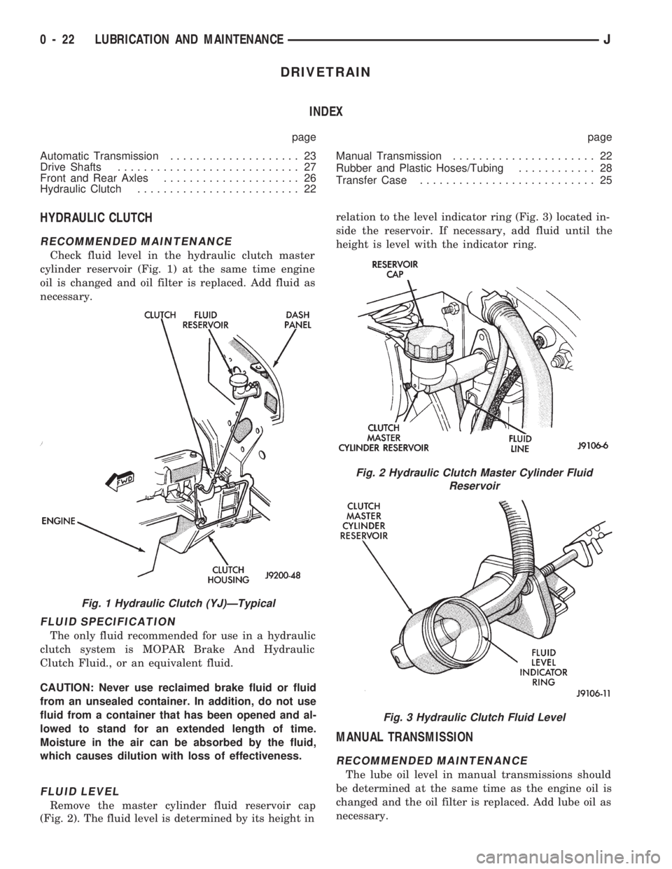
Check fluid level in the hydraulic clutch master
cylinder reservoir (Fig. 1) at the same time engine
oil is changed and oil filter is replaced. Add fluid as
necessary.
FLUID SPECIFICATION
The only fluid recommended for use in a hydraulic
clutch system is MOPAR Brake And Hydraulic
Clutch Fluid., or an equivalent fluid.
CAUTION: Never use reclaimed brake fluid or fluid
from an unsealed container. In addition, do not use
fluid from a container that has been opened and al-
lowed to stand for an extended length of time.
Moisture in the air can be absorbed by the fluid,
which causes dilution with loss of effectiveness.
FLUID LEVEL
Remove the master cylinder fluid reservoir cap
(Fig. 2). The fluid level is determined by its height inrelation to the level indicator ring (Fig. 3) located in-
side the reservoir. If necessary, add fluid until the
height is level with the indicator ring.
MANUAL TRANSMISSION
RECOMMENDED MAINTENANCE
The lube oil level in manual transmissions should
be determined at the same time as the engine oil is
changed and the oil filter is replaced. Add lube oil as
necessary.
Fig. 1 Hydraulic Clutch (YJ)ÐTypical
Fig. 2 Hydraulic Clutch Master Cylinder Fluid
Reservoir
Fig. 3 Hydraulic Clutch Fluid Level
0 - 22 LUBRICATION AND MAINTENANCEJ
Page 24 of 1784
Under normal driving conditions, manual trans-
mission lube oil should be changed after each 60
000-km (37,500 miles). With severe driving condi-
tions, after each 29 000-km (18,000 miles).
LUBRICANT SPECIFICATION
When it becomes necessary to add to or change the
lube oil in a Jeeptmanual transmission, use SAE
75W-90, API Quality Grade GL-5 gear lubricant.
LUBRICANT LEVEL
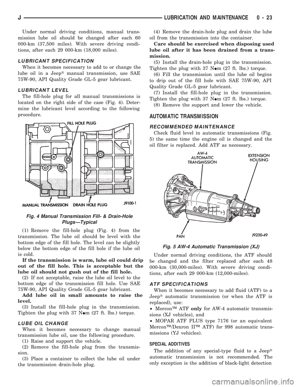
The fill-hole plug for all manual transmissions is
located on the right side of the case (Fig. 4). Deter-
mine the lubricant level according to the following
procedure.
(1) Remove the fill-hole plug (Fig. 4) from the
transmission. The lube oil should be level with the
bottom edge of the fill hole. The level can be slightly
below the bottom edge of the fill hole if the lube oil
is cold.
If the transmission is warm, lube oil could drip
out of the fill hole. This is acceptable but the
lube oil should not gush out of the fill hole.
(2) If not acceptable, raise the lube oil level to the
bottom edge of the transmission fill hole. Use SAE
75W-90, API Quality Grade GL-5 gear lubricant.
Add lube oil in small amounts to raise the
level.
(3) Install the fill-hole plug in the transmission.
Tighten the plug with 37 NIm (27 ft. lbs.) torque.
LUBE OIL CHANGE
When it becomes necessary to change manual
transmission lube oil, use the following procedure.
(1) Raise and support the vehicle.
(2) Remove the fill-hole plug from the transmis-
sion.
(3) Place a container to collect the lube oil under
the transmission drain-hole plug.(4) Remove the drain-hole plug and drain the lube
oil from the transmission into the container.
Care should be exercised when disposing used
lube oil after it has been drained from a trans-
mission.
(5) Install the drain-hole plug in the transmission.
Tighten the plug with 37 NIm (27 ft. lbs.) torque.
(6) Fill the transmission until the lube oil begins
to drip out of the fill hole with SAE 75W-90, API
Quality Grade GL-5 gear lubricant.
(7) Install the fill-hole plug in the transmission.
Tighten the plug with 37 NIm (27 ft. lbs.) torque.
(8) Remove the support and lower the vehicle.
AUTOMATIC TRANSMISSION
RECOMMENDED MAINTENANCE
Check fluid level in automatic transmissions (Fig.
5) the same time the engine oil is changed and the
oil filter is replaced. Add ATF as necessary.
Under normal driving conditions, the ATF should
be changed and the filter replaced after each 48
000-km (30,000-miles). With severe driving condi-
tions, after each 29 000-km (12,000-miles).
ATF SPECIFICATIONS
When it becomes necessary to add fluid (ATF) to a
Jeeptautomatic transmission (or when the ATF is
replaced), use:
²MerconŸ ATFonlyfor AW-4 automatic transmis-
sions (XJ vehicles), and
²MOPAR ATF PLUS type 7176 (or an equivalent
MerconŸ/Dexron IIŸ ATF) for 998 automatic trans-
missions (YJ vehicles).
SPECIAL ADDITIVES
The addition of any special-type fluid to a Jeept
automatic transmission is not recommended. The
only exception is the addition of black-light detection
Fig. 5 AW-4 Automatic Transmission (XJ)
Fig. 4 Manual Transmission Fill- & Drain-Hole
PlugsÐTypical
JLUBRICATION AND MAINTENANCE 0 - 23
Page 25 of 1784
dye to aid in detecting the source of ATF leaks. The
use of transmission sealing additives should also be
avoided.
Black-light detection dye is factory-installed in
automatic transmissions and, unless the ATF
has been drained and re-placed, it is not neces-
sary to add dye.
ATF LEVEL
Determine the ATF level according to the following
procedure.
WARNING: USE EXTREME CAUTION WHEN THE
ENGINE IS OPERATING. DO NOT PUT YOUR
HANDS NEAR THE DRIVE BELT, PULLEYS OR FAN
BLADE. DO NOT STAND IN A DIRECT LINE WITH
THE FAN BLADE.
(1) Operate the engine and allow the automatic
transmission sufficient time to warm to the normal
operating temperature (77ÉC/170ÉF).
When at normal operating temperature, ATF
will be uncomfortable to fingertips when the
dipstick is touched. Normally, 25 km (15 miles) is
a sufficient driving distance for a transmission
to warm to normal operating temperature (77ÉC/
170ÉF).
(2) Place the vehicle on a level surface.
(3) Operate the engine at idle speed.
(4) Engage the parking brake.
(5) Place a block in front of and at the rear of one
wheel/tire to prevent vehicle movement.
(6) Depress the brake pedal and move the trans-
mission selector lever through all the positions and
then place the selector lever in NEUTRAL position.
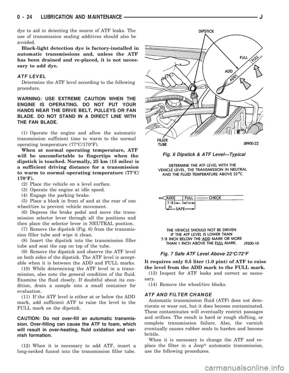
(7) Remove the dipstick (Fig. 6) from the transmis-
sion filler tube and wipe it clean.
(8) Insert the dipstick into the transmission filler
tube and seat the cap on top of the tube.
(9) Remove the dipstick and observe the ATF level
on both sides of the dipstick. The ATF level is accept-
able when it is between the ADD and FULL marks.
(10) While determining the ATF level in a trans-
mission, also note the general condition of the fluid.
Examine the fluid closely. If doubtful about its con-
dition, drain a sample into a small container for
evaluation.
(11) If the ATF level is either at or below the ADD
mark, add sufficient ATF to raise the level to the
FULL mark on the dipstick.
CAUTION: Do not over-fill an automatic transmis-
sion. Over-filling can cause the ATF to foam, which
will result in over-heating, fluid oxidation and var-
nish formation.
(12) When it is necessary to add ATF, insert a
long-necked funnel into the transmission filler tube.It requires only 0.5 liter (1.0 pint) of ATF to raise
the level from the ADD mark to the FULL mark.
(13) Inspect for ATF leaks and correct as neces-
sary.
(14) Remove the wheel/tire blocks.
ATF AND FILTER CHANGE
Automatic transmission fluid (ATF) does not dete-
riorate or wear out, but it does become contaminated.
These contaminates will eventually restrict passages
and orifices. The result is hard or rough shifting, or
complete transmission failure. Also, the varnish
eventually causes rubber seals to harden and become
brittle.
When it is necessary to change the ATF and re-
place the filter in a Jeeptautomatic transmission,
use the following procedures.
Fig. 6 Dipstick & ATF LevelÐTypical
Fig. 7 Safe ATF Level Above 22ÉC/72ÉF
0 - 24 LUBRICATION AND MAINTENANCEJ
Page 26 of 1784

DRAINING ATF/FILTER REMOVAL
Drain the automatic transmission fluid (ATF) im-
mediately after stopping the engine (before the ATF
cools).
(1) Raise and support the vehicle.
(2) Loosen the transmission pan bolts and drain
the original ATF into an appropriate container. Re-
move the pan bolts, the pan and the gasket.
Care should be exercised when disposing used
ATF after it has been drained from a vehicle
transmission.
(3) Remove the screws and the ATF filter (Fig. 8).
Discard the filter.
FILTER INSTALLATION/ATF RE-FILL
(1) Install a replacement ATF filter. Tighten the
screws with 4 NIm (35 in. lbs.) torque.
(2) Clean the pan thoroughly. Install a replace-
ment gasket on the pan. Install the pan with the at-
taching bolts:
²model AW-4 transmission Ð tighten the pan bolts
with 7 NIm (60 in. lbs.) torque; and
²model 998 transmission Ð tighten the pan bolts
with 17 NIm (150 in. lbs.) torque.
(3) Remove the support and lower the vehicle.
(4) Pour approximately 4.7 liters (5 quarts) of ATF
into the filler tube. Use MerconŸ ATF for AW-4 au-
tomatic transmissions. Use MOPAR ATF PLUS type
7176 or equivalent, for 998 automatic transmissions.
(5) Place a block in front of and at the rear of one
wheel/tire to prevent vehicle movement.
(6) Start the engine and allow it to idle a few min-
utes.
(7) Apply the brake pedal and engage the parking
brake. Move the transmission selector lever through
all positions, then place the selector lever in NEU-
TRAL position.(8) With the transmission at normal operating
temperature, observe the ATF level on the dipstick.
Add ATF (if necessary) to raise the level to the
FULL mark on the dipstick.Only 0.5 liter (1.0 pint)
will raise the level from the ADD mark to the
FULL mark when the ATF is at normal operat-
ing temperature.
(9) Inspect for fluid leaks and correct as necessary.
(10) Remove the wheel/tire blocks.
TRANSFER CASE
RECOMMENDED MAINTENANCE
The fluid (ATF) level in transfer cases should be
determined at the same time as the engine oil is
changed and the oil filter is replaced. Add ATF as
necessary.
In addition, transfer case ATF should be changed
after each 48 000-km (30,000-miles) interval of vehi-
cle operation has elapsed.
FLUID SPECIFICATIONS
If it is necessary to add fluid to a transfer case (or
when the fluid is changed), use MOPAR ATF PLUS
type 7176 or an equivalent MerconŸ/Dexron IIŸ
ATF.
FLUID LEVEL
The transfer case fill-hole plug is located at the
rear of the housing (Fig. 9).
Determine the transfer case fluid (ATF) level ac-
cording to the following procedure.
(1) Raise and support the vehicle.
(2) Remove the fill-hole plug from the transfer
case. The ATF level should be at the bottom edge of
the fill hole. The level can be slightly below the bot-
tom edge of the fill hole if the fluid is cold.
Fig. 9 Transfer CaseÐTypical
Fig. 8 ATF FilterÐTypical
JLUBRICATION AND MAINTENANCE 0 - 25
Page 103 of 1784
charges when the PCM supplies a ground. By switch-
ing the ground path on and off, the PCM regulates
ignition timing.
The sensors and switches that provide inputs to the
powertrain control module (PCM) comprise the En-
gine Control System. It is also comprised of the PCM
Outputs (engine control devices that the are operated
by the PCM).
SYSTEM DIAGNOSIS
The powertrain control module (PCM) tests many
of its own input and output circuits. If a Diagnostic
Trouble Code (DTC) is found in a major system, this
information is stored in the PCM memory. Refer to
On-Board Diagnostics in the MFI SystemÐGeneral
Diagnosis section of this group for DTC information.
POWERTRAIN CONTROL MODULE (PCM)
The PCM operates the fuel system. The PCM was
formerly referred to as the SBEC or engine control-
ler. The PCM is a pre-programmed, dual micropro-
cessor digital computer. It regulates ignition timing,
air-fuel ratio, emission control devices, charging sys-
tem, speed control, air conditioning compressor
clutch engagement and idle speed. The PCM can
adapt its programming to meet changing operating
conditions.
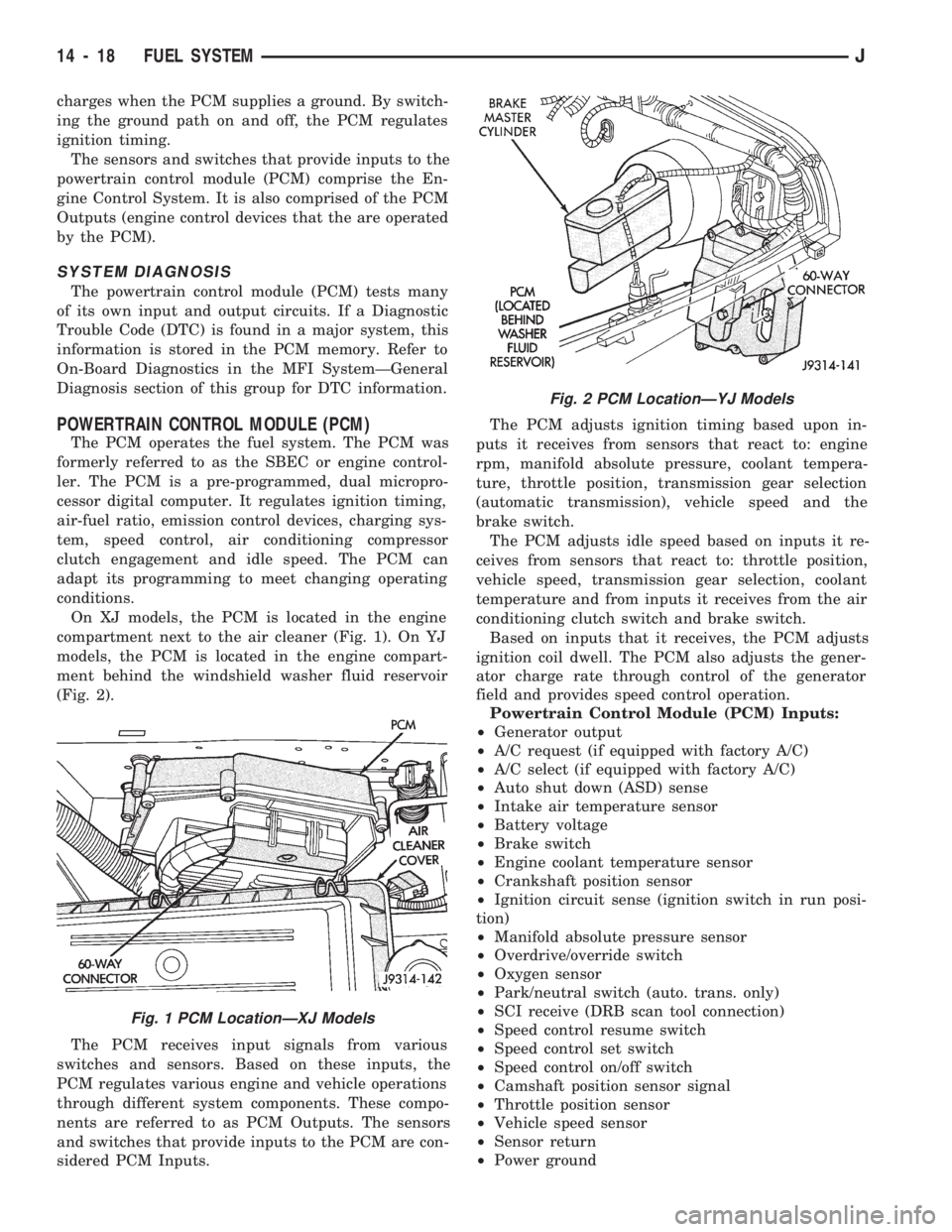
On XJ models, the PCM is located in the engine
compartment next to the air cleaner (Fig. 1). On YJ
models, the PCM is located in the engine compart-
ment behind the windshield washer fluid reservoir
(Fig. 2).
The PCM receives input signals from various
switches and sensors. Based on these inputs, the
PCM regulates various engine and vehicle operations
through different system components. These compo-
nents are referred to as PCM Outputs. The sensors
and switches that provide inputs to the PCM are con-
sidered PCM Inputs.The PCM adjusts ignition timing based upon in-
puts it receives from sensors that react to: engine
rpm, manifold absolute pressure, coolant tempera-
ture, throttle position, transmission gear selection
(automatic transmission), vehicle speed and the
brake switch.
The PCM adjusts idle speed based on inputs it re-
ceives from sensors that react to: throttle position,
vehicle speed, transmission gear selection, coolant
temperature and from inputs it receives from the air
conditioning clutch switch and brake switch.
Based on inputs that it receives, the PCM adjusts
ignition coil dwell. The PCM also adjusts the gener-
ator charge rate through control of the generator
field and provides speed control operation.
Powertrain Control Module (PCM) Inputs:
²Generator output
²A/C request (if equipped with factory A/C)
²A/C select (if equipped with factory A/C)
²Auto shut down (ASD) sense
²Intake air temperature sensor
²Battery voltage
²Brake switch
²Engine coolant temperature sensor
²Crankshaft position sensor
²Ignition circuit sense (ignition switch in run posi-
tion)
²Manifold absolute pressure sensor
²Overdrive/override switch
²Oxygen sensor
²Park/neutral switch (auto. trans. only)
²SCI receive (DRB scan tool connection)
²Speed control resume switch
²Speed control set switch
²Speed control on/off switch
²Camshaft position sensor signal
²Throttle position sensor
²Vehicle speed sensor
²Sensor return
²Power ground
Fig. 1 PCM LocationÐXJ Models
Fig. 2 PCM LocationÐYJ Models
14 - 18 FUEL SYSTEMJ