1994 JEEP CHEROKEE spare wheel
[x] Cancel search: spare wheelPage 150 of 1784
ABS BRAKE DIAGNOSIS
INDEX
page page
ABS Fault Diagnosis....................... 4
ABS System Wiring and Electrical Circuits...... 4
ABS Warning Light Display.................. 3
Brake Warning Light Display................. 4
Diagnosis Procedures...................... 3
ECU Diagnosis........................... 4
HCU Diagnosis........................... 4Loss of Sensor Input....................... 3
Operating Sound Levels.................... 3
Rear Speed Sensor Air Gap................. 3
Steering Response........................ 3
Vehicle Response in Antilock Mode............ 3
Wheel/Tire Size and Input Signals............. 3
DIAGNOSIS PROCEDURES
ABS diagnosis involves three basic steps. First is
observation of the warning light display. Second is a
visual examination for low fluid level, leaks, parking
brakes applied, or obvious damage to system compo-
nents or wires. The third step involves using the
DRB II scan tool to identify a faulty component.
The visual examination requires a check of reser-
voir fluid level and all system components. Things to
look for are leaks, loose connections, or obvious com-
ponent damage.
The final diagnosis step involves using the DRB II
scan tool to determine the specific circuit or compo-
nent at fault. The tester is connected to the ABS di-
agnostic connector in the passenger compartment.
The connector is at the driver side of the center con-
sole under the instrument panel. Refer to the DRB II
scan tool Manual for tester procedures. Also refer to
the ABS Fault Diagnosis charts at the end of this
section for additional diagnosis information.
Initial faults should be cleared and the vehicle road
tested to reset any faults that remain in the system.
Faults can be cleared with the DRB II scan tool.
REAR SPEED SENSOR AIR GAP
The front wheel sensors are fixed and cannot be ad-
justed. Only the rear sensor air gap is adjustable. Air
gap must be set with a brass feeler gauge.
Correct air gap is important to proper signal gen-
eration. An air gap that is too large may cause com-
plete loss of sensor input. Or, a gap that is too small
could produce a false input signal, or damaging con-
tact between the sensor and tone ring.
WHEEL/TIRE SIZE AND INPUT SIGNALS
Antilock system operation is dependant on accurate
signals from the wheel speed sensors. Ideally, the ve-
hicle wheels and tires should all be the same size
and type. However, the Jeep ABS system is designed
to function with a compact spare tire installed.
OPERATING SOUND LEVELS
The ABS pump and solenoid valves may produce
some sound as they cycle on and off. This is a normal
condition and should not be mistaken for faulty oper-
ation.
VEHICLE RESPONSE IN ANTILOCK MODE
During antilock braking, the HCU solenoid valves
cycle rapidly in response to ECU inputs.
The driver will experience a pulsing sensation
within the vehicle as the solenoids decrease, hold, or
increase pressure as needed. A pulsing brake pedal
will also be noted.
The pulsing sensation occurs as the solenoids cycle
during antilock mode braking. A slight pulse in the
brake pedal may also be noted during the dynamic
self check part of system initialization.
STEERING RESPONSE
A modest amount of steering input is required dur-
ing extremely high deceleration braking, or when
braking on differing traction surfaces. An example of
differing traction surfaces would be when the left
side wheels are on ice and the right side wheels are
on dry pavement.
LOSS OF SENSOR INPUT
Sensor malfunctions will most likely be due to
loose connections, damaged sensor wires, incorrect
rear sensor air gap, or a malfunctioning sensor. Ad-
ditional causes of sensor faults would be sensor and
tone ring misalignment or damage.
ABS WARNING LIGHT DISPLAY
ABS Light Illuminates At Startup
The amber ABS light illuminates at startup as
part of the system self check feature. The light illu-
minates for 2-3 seconds then goes off as part of the
normal self check routine.
ABS Light Remains On After Startup
An ABS system fault is indicated when the light
remains on after startup. Diagnosis with the DRB II
JBRAKES 5 - 3
Page 1040 of 1784
POWER STEERING SYSTEM DIAGNOSIS
PUMP PRESSURE TEST
(1) Check belt tension and adjust as necessary.
(2) Disconnect high pressure hose at gear or pump.
Use a container for dripping fluid.
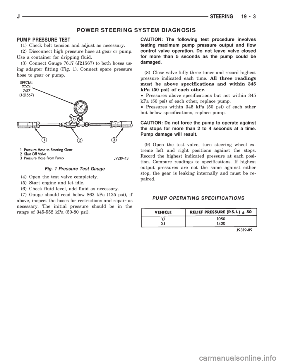
(3) Connect Gauge 7617 (J21567) to both hoses us-
ing adapter fitting (Fig. 1). Connect spare pressure
hose to gear or pump.
(4) Open the test valve completely.
(5) Start engine and let idle.
(6) Check fluid level, add fluid as necessary.
(7) Gauge should read below 862 kPa (125 psi), if
above, inspect the hoses for restrictions and repair as
necessary. The initial pressure should be in the
range of 345-552 kPa (50-80 psi).CAUTION: The following test procedure involves
testing maximum pump pressure output and flow
control valve operation. Do not leave valve closed
for more than 5 seconds as the pump could be
damaged.
(8) Close valve fully three times and record highest
pressure indicated each time.All three readings
must be above specifications and within 345
kPa (50 psi) of each other.
²Pressures above specifications but not within 345
kPa (50 psi) of each other, replace pump.
²Pressures within 345 kPa (50 psi) of each other
but below specifications, replace pump.
CAUTION: Do not force the pump to operate against
the stops for more than 2 to 4 seconds at a time.
Pump damage will result.
(9) Open the test valve, turn steering wheel ex-
treme left and right positions against the stops.
Record the highest indicated pressure at each posi-
tion. Compare readings to specifications. If highest
output pressures are not the same against either
stop, the gear is leaking internally and must be re-
paired.
Fig. 1 Pressure Test Gauge
PUMP OPERATING SPECIFICATIONS
JSTEERING 19 - 3
Page 1444 of 1784
WHEELS AND TIRES
CONTENTS
page page
SPECIFICATIONS....................... 11
TIRES................................. 1VEHICLE VIBRATION..................... 9
WHEELS............................... 6
TIRES
INDEX
page page
Cleaning of Tires.......................... 2
General Information........................ 1
Pressure Gauges......................... 2
Repairing Leaks.......................... 3
Replacement Tires........................ 2Rotation................................ 3
Tire Inflation Pressures..................... 2
Tire Noise or Vibration..................... 4
Tire Wear Patterns........................ 4
Tread Wear Indicators...................... 3
GENERAL INFORMATION
Tires are designed for each specific vehicle. They
provide the best overall performance for normal op-
eration. The ride and handling characteristics match
the vehicle's requirements. With proper care they
will give excellent reliability, traction, skid resis-
tance, and tread life. These tires have specific load
carrying capacities. When correctly inflated, they
will operate properly.
Tires used in cool climates, and with light loads
will have a longer life than tires used in hot climates
with heavy loads. Abrasive road surfaces will accel-
erate tire wear.
Driving habits have more effect on tire life than
any other factor. Careful drivers will obtain much
greater mileage than careless drivers.
Driving habits that shorten the life of any tire;
²Rapid acceleration and deceleration
²Severe application of brakes
²High-speed driving
²Taking turns at excessive speeds
²Striking curbs and other obstacles
It is very important to follow the tire rotation in-
terval
IDENTIFICATION
Tire type, size, aspect ratio and speed rating are
encoded in the letters and numbers imprinted on the
side wall of the tire. Refer to the chart to decipher
the tire identification code (Fig. 1).
Performance tires will have a speed rating letter
after the aspect ratio number. The speed rating isnot always printed on the tire sidewall. The letterS
indicates that the tire is speed rated up to 112 mph.
²Qup to 100 mph
²Tup to 118 mph
²Uup to 124 mph
²Hup to 130 mph
²Vup to 149 mph
²Zmore than 149 mph (consult the tire manufac-
turer for the specific speed rating)
An All Season type tire will have eitherM+S,M
&SorMÐS(indicating mud and snow traction) im-
printed on the side wall.
RADIAL-PLY TIRES
Radial-ply tires improve handling, tread life, ride
quality and decrease rolling resistance.
Radial-ply tires must always be used in sets of
four. Under no circumstances should they be used on
the front only. They may be mixed with temporary
spare tires when necessary, but reduced speeds are
recommended.
Radial-ply tires have the same load-carrying capac-
ity as other types of tires of the same size. They use
the same recommended inflation pressures.
SPARE TIRE (TEMPORARY)
The compact spare tire is designed for emergency
use only. The original tire should be repaired and re-
installed at the first opportunity. Refer to Owner's
Manual for complete details.
JWHEELS AND TIRES 22 - 1
Page 1546 of 1784
INTERIOR COMPONENTS
INDEX
page page
Assist HandleÐXJ Vehicles................ 118
B/C-Pillar and Liftgate Pillar Trim CoversÐ
XJ Vehicles.......................... 116
Bucket Seat Cushion and Cover............. 98
Bucket Seat Platform and Tracks........... 105
Bucket Seatback Cover and Frame.......... 100
Bucket Seatback Reconditioning............ 102
Carpets and Floor Mats................... 129
Dash Panel Insulation Panel................ 95
Front Bucket Seats....................... 97
Front Carpet/MatÐXJ Vehicles............. 129
Front Inner Scuff Plate/Cowl Side Trim PanelÐ
XJ Vehicles.......................... 114
Front Shoulder Belt/BuckleÐXJ Vehicles...... 119
Full Floor ConsoleÐXJ Vehicles............ 125
Headliner.............................. 121
I/P Ash Receiver Tray Lamp................ 92
I/P Tweeter Speaker/Courtesy Lamp Support
Bracket.............................. 95
Instrument Cluster Bezel................... 91
Instrument Cluster/Switch/Lighter/Radio/Hevac . . . 91
Instrument Panel......................... 93
Interior Trim Panels and Scuff PlatesÐXJ Vehicles. 112
Jack StorageÐXJ Vehicles................ 127
Mini-Floor ConsoleÐXJ Vehicles............ 124
Outer Scuff PlatesÐXJ Vehicles............ 118
Power Bucket Seat Components............ 106
Quarter and Wheelhouse Trim PanelsÐ
XJ Vehicles.......................... 115
Quarter Trim Panel ExtensionÐXJ Vehicles . . . 115
Rear Carpet/MatÐXJ Vehicles.............. 130
Rear Seat Cushion CoverÐXJ Vehicles...... 107
Rear Seat Cushion ReconditioningÐXJ Vehicles . 108
Rear Seat CushionÐXJ Vehicles............ 107
Rear Seatback CoverÐXJ Vehicles.......... 111
Rear Seatback Latch Striker and BumperÐ
XJ Vehicles.......................... 111
Rear Seatback ReconditioningÐXJ Vehicles . . . 111
Rear SeatbackÐXJ Vehicles............... 109
Rear Shoulder/Lap Belt/BuckleÐXJ Vehicles . . . 120
Spare Tire/Wheel Holddown and Floor BracketsÐ
XJ Vehicles.......................... 128
Sunvisors............................. 124
Windshield Side MouldingÐXJ Vehicles...... 114
INSTRUMENT CLUSTER BEZEL
REMOVAL
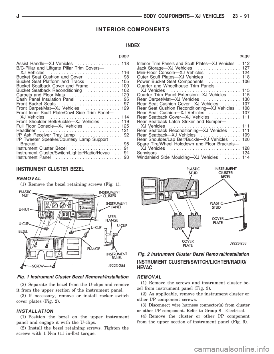
(1) Remove the bezel retaining screws (Fig. 1).
(2) Separate the bezel from the U-clips and remove
it from the upper section of the instrument panel.
(3) If necessary, remove or install rocker switch
cover plates (Fig. 2).
INSTALLATION
(1) Position the bezel on the upper instrument
panel and engage it with the U-clips.
(2) Install the bezel retaining screws. Tighten the
screws with 1 Nzm (11 in-lbs) torque.
INSTRUMENT CLUSTER/SWITCH/LIGHTER/RADIO/
HEVAC
REMOVAL
(1) Remove the screws and instrument cluster be-
zel from instrument panel (Fig. 3).
(2) As applicable, remove the instrument cluster or
other I/P component screws.
(3) Disconnect wire harness connector(s) from cluster
or other I/P component. Refer to Group 8ÐElectrical.
(4) Remove the cluster or other I/P component
from the upper section of instrument panel (Fig. 9).
Fig. 1 Instrument Cluster Bezel Removal/Installation
Fig. 2 Instrument Cluster Bezel Removal/Installation
JBODY COMPONENTSÐXJ VEHICLES 23 - 91
Page 1583 of 1784
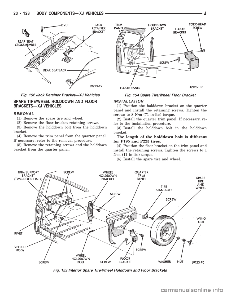
SPARE TIRE/WHEEL HOLDDOWN AND FLOOR
BRACKETSÐXJ VEHICLES
REMOVAL
(1) Remove the spare tire and wheel.
(2) Remove the floor bracket retaining screws.
(3) Remove the holddown bolt from the holddown
bracket.
(4) Remove the trim panel from the quarter panel.
If necessary, refer to the removal procedure.
(5) Remove the retaining screws and the holddown
bracket from the quarter panel.
INSTALLATION
(1) Position the holddown bracket on the quarter
panel and install the retaining screws. Tighten the
screws to 8 Nzm (71 in-lbs) torque.
(2) Install the quarter trim panel. If necessary, re-
fer to the installation procedure.
(3) Install the holddown bolt in the holddown
bracket.
The length of the holddown bolt is different
for P195 and P225 tires.
(4) Position the floor bracket on the trim panel and
install the retaining screws. Tighten the screws to 1
Nzm (11 in-lbs) torque.
(5) Install the spare tire and wheel.
Fig. 153 Interior Spare Tire/Wheel Holddown and Floor Brackets
Fig. 152 Jack Retainer BracketÐXJ VehiclesFig. 154 Spare Tire/Wheel Floor Bracket
23 - 128 BODY COMPONENTSÐXJ VEHICLESJ
Page 1584 of 1784
CARPETS AND FLOOR MATS
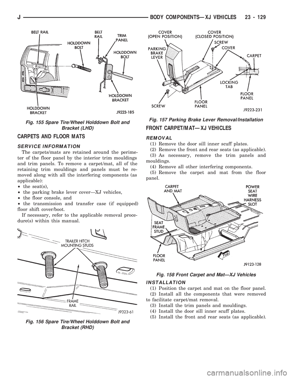
SERVICE INFORMATION
The carpets/mats are retained around the perime-
ter of the floor panel by the interior trim mouldings
and trim panels. To remove a carpet/mat, all of the
retaining trim mouldings and panels must be re-
moved along with all the interfering components (as
applicable):
²the seat(s),
²the parking brake lever coverÐXJ vehicles,
²the floor console, and
²the transmission and transfer case (if equipped)
floor shift cover/boot.
If necessary, refer to the applicable removal proce-
dure(s) within this manual.
FRONT CARPET/MATÐXJ VEHICLES
REMOVAL
(1) Remove the door sill inner scuff plates.
(2) Remove the front and rear seats (as applicable).
(3) As necessary, remove the trim panels and
mouldings.
(4) Remove all other interfering components.
(5) Remove the carpet and mat from the floor
panel.
INSTALLATION
(1) Position the carpet and mat on the floor panel.
(2) Install all the components that were removed
to facilitate carpet/mat removal.
(3) Install the trim panels and mouldings.
(4) Install the door sill inner scuff plates.
(5) Install the front and rear seats (as applicable).
Fig. 156 Spare Tire/Wheel Holddown Bolt and
Bracket (RHD)
Fig. 155 Spare Tire/Wheel Holddown Bolt and
Bracket (LHD)Fig. 157 Parking Brake Lever Removal/Installation
Fig. 158 Front Carpet and MatÐXJ Vehicles
JBODY COMPONENTSÐXJ VEHICLES 23 - 129
Page 1589 of 1784
EXTERIOR COMPONENTS
INDEX
page page
Battery Tray........................... 140
Body Extension Panels and FasciasÐYJ
Renegade Vehicles..................... 147
Body Side Step Moulding................. 145
Body Stripes/Decals..................... 153
Cowl Grille and Screen................... 139
Cowl Weatherstrip Seal................... 139
Exterior Nameplates (Adhesive-Backed)....... 158
External Spare/Wheel Tire Carrier........... 172
Fender Flare........................... 144
Fender Inner Splash Shields............... 147
Fender Splash Aprons.................... 147
Fenders............................... 141
Fog LampÐYJ Renegade Vehicles.......... 150
Front Fascia and Skid PlateÐYJ Renegade
Vehicles............................. 148
Front Fender Extension PanelÐYJ Renegade
Vehicles............................. 149
Fuel Filler Protector/Nozzle................ 158
Half Metal Door Mirror (External)............ 158
Hard Top Liftgate Glass.................. 162
Hard Top Repair........................ 165
Hard Top Roof Vent..................... 165
Hard Top Service....................... 164
Hard Top Service Information.............. 164Hood................................. 137
Hood Alignment......................... 138
Hood Insulator Panel..................... 138
Hood Safety Latch....................... 139
Liftgate Glass Weatherstrip Seal Replacement . . 163
Radiator Grille Applique................... 134
Rear Fascia and Skid PlateÐYJ Renegade
Vehicles............................. 152
Rear Quarter Extension PanelÐYJ Renegade
Vehicles............................. 151
Rocker Extension PanelÐYJ Renegade
Vehicles............................. 150
Soft Top Service........................ 167
Soft Top Service Information............... 166
Sport Bar............................. 171
Tailgate Adjustment...................... 160
Tailgate Hinge.......................... 159
Tailgate Latch and Release Handle.......... 160
Tailgate Latch Striker..................... 161
Tailgate Lock Cylinder.................... 160
Tailgate Service......................... 159
Tailgate Service Information................ 159
Tailgate Weatherstrip Seal................. 161
Wheelhouse Splash Liners................ 146
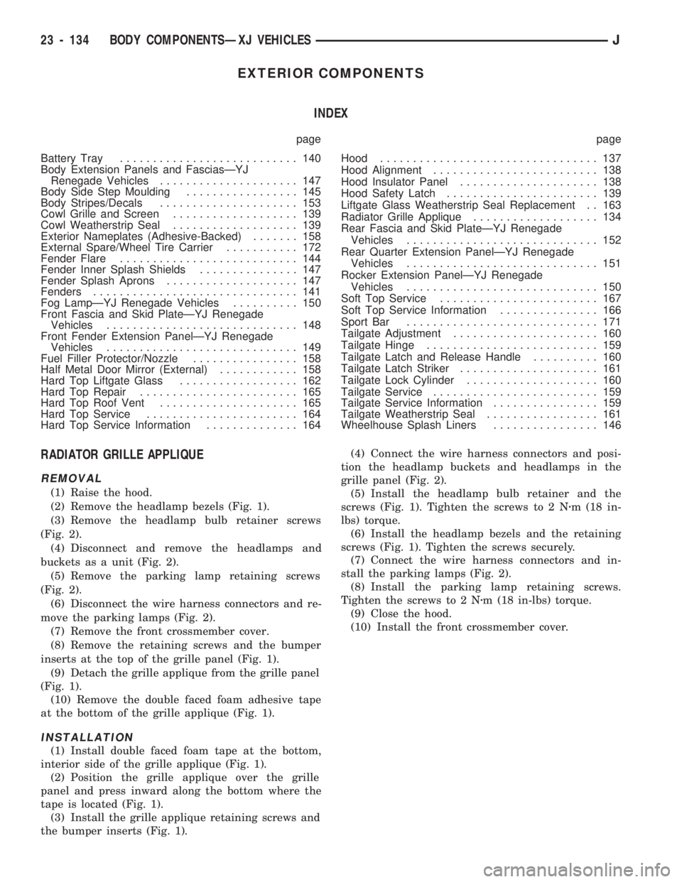
RADIATOR GRILLE APPLIQUE
REMOVAL
(1) Raise the hood.
(2) Remove the headlamp bezels (Fig. 1).
(3) Remove the headlamp bulb retainer screws
(Fig. 2).
(4) Disconnect and remove the headlamps and
buckets as a unit (Fig. 2).
(5) Remove the parking lamp retaining screws
(Fig. 2).
(6) Disconnect the wire harness connectors and re-
move the parking lamps (Fig. 2).
(7) Remove the front crossmember cover.
(8) Remove the retaining screws and the bumper
inserts at the top of the grille panel (Fig. 1).
(9) Detach the grille applique from the grille panel
(Fig. 1).
(10) Remove the double faced foam adhesive tape
at the bottom of the grille applique (Fig. 1).
INSTALLATION
(1) Install double faced foam tape at the bottom,
interior side of the grille applique (Fig. 1).
(2) Position the grille applique over the grille
panel and press inward along the bottom where the
tape is located (Fig. 1).
(3) Install the grille applique retaining screws and
the bumper inserts (Fig. 1).(4) Connect the wire harness connectors and posi-
tion the headlamp buckets and headlamps in the
grille panel (Fig. 2).
(5) Install the headlamp bulb retainer and the
screws (Fig. 1). Tighten the screws to 2 Nzm (18 in-
lbs) torque.
(6) Install the headlamp bezels and the retaining
screws (Fig. 1). Tighten the screws securely.
(7) Connect the wire harness connectors and in-
stall the parking lamps (Fig. 2).
(8) Install the parking lamp retaining screws.
Tighten the screws to 2 Nzm (18 in-lbs) torque.
(9) Close the hood.
(10) Install the front crossmember cover.
23 - 134 BODY COMPONENTSÐXJ VEHICLESJ
Page 1627 of 1784
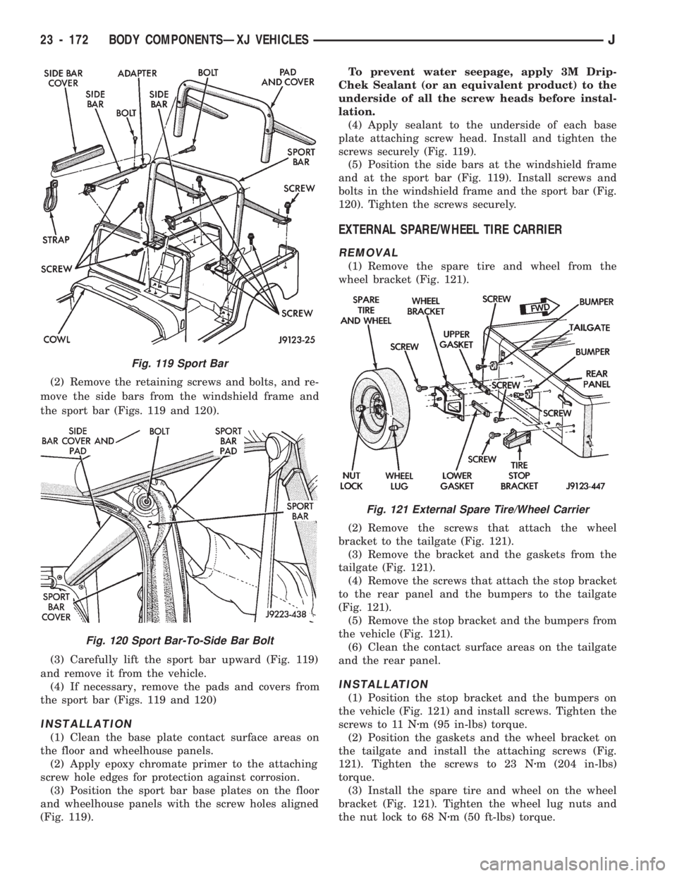
(2) Remove the retaining screws and bolts, and re-
move the side bars from the windshield frame and
the sport bar (Figs. 119 and 120).
(3) Carefully lift the sport bar upward (Fig. 119)
and remove it from the vehicle.
(4) If necessary, remove the pads and covers from
the sport bar (Figs. 119 and 120)
INSTALLATION
(1) Clean the base plate contact surface areas on
the floor and wheelhouse panels.
(2) Apply epoxy chromate primer to the attaching
screw hole edges for protection against corrosion.
(3) Position the sport bar base plates on the floor
and wheelhouse panels with the screw holes aligned
(Fig. 119).To prevent water seepage, apply 3M Drip-
Chek Sealant (or an equivalent product) to the
underside of all the screw heads before instal-
lation.
(4) Apply sealant to the underside of each base
plate attaching screw head. Install and tighten the
screws securely (Fig. 119).
(5) Position the side bars at the windshield frame
and at the sport bar (Fig. 119). Install screws and
bolts in the windshield frame and the sport bar (Fig.
120). Tighten the screws securely.
EXTERNAL SPARE/WHEEL TIRE CARRIER
REMOVAL
(1) Remove the spare tire and wheel from the
wheel bracket (Fig. 121).
(2) Remove the screws that attach the wheel
bracket to the tailgate (Fig. 121).
(3) Remove the bracket and the gaskets from the
tailgate (Fig. 121).
(4) Remove the screws that attach the stop bracket
to the rear panel and the bumpers to the tailgate
(Fig. 121).
(5) Remove the stop bracket and the bumpers from
the vehicle (Fig. 121).
(6) Clean the contact surface areas on the tailgate
and the rear panel.
INSTALLATION
(1) Position the stop bracket and the bumpers on
the vehicle (Fig. 121) and install screws. Tighten the
screws to 11 Nzm (95 in-lbs) torque.
(2) Position the gaskets and the wheel bracket on
the tailgate and install the attaching screws (Fig.
121). Tighten the screws to 23 Nzm (204 in-lbs)
torque.
(3) Install the spare tire and wheel on the wheel
bracket (Fig. 121). Tighten the wheel lug nuts and
the nut lock to 68 Nzm (50 ft-lbs) torque.
Fig. 119 Sport Bar
Fig. 120 Sport Bar-To-Side Bar Bolt
Fig. 121 External Spare Tire/Wheel Carrier
23 - 172 BODY COMPONENTSÐXJ VEHICLESJ