1994 JEEP CHEROKEE oil capacity
[x] Cancel search: oil capacityPage 253 of 1784

The coolant reserve/overflow system consists of a
radiator mounted pressurized cap, a plastic reserve/
overflow tank (Figs. 21, 22 or 23), a tube connecting
the radiator and tank, and an overflow tube on the
side of the tank.
TANK REMOVAL/INSTALLATION
(1) Remove the tube clamp at the tank and remove
tube.(2) On YJ models, remove the windshield washer
reservoir and its mounting bracket.
(3) Remove the tank mounting bolts and remove
tank.
(4) Reverse the preceding steps for installation.
RADIATOR PRESSURE CAP
All radiators are equipped with a pressure cap.
This cap releases pressure at some point within a
range of 83-110 kPa (12-16 psi). The pressure relief
point (in pounds) is engraved on top of the cap (Fig.
24).
The cooling system will operate at pressures
slightly above atmospheric pressure. This results in a
higher coolant boiling point allowing increased radi-
ator cooling capacity. The cap (Fig. 24) contains a
spring-loaded pressure relief valve. This valve opens
when system pressure reaches the release range of
83-110 kPa (12-16 psi).
A vent valve in the center of the cap allows a small
coolant flow through the cap when coolant is below
boiling temperature. The valve is completely closed
when boiling point is reached. As coolant cools, it
contracts and creates a vacuum in the cooling sys-
tem. This causes the vacuum valve to open and cool-
ant in reserve/overflow tank to be drawn through
connecting hose into radiator. If the vacuum valve is
stuck shut, radiator hoses will collapse on cool-down.
A rubber gasket seals the radiator filler neck. This
is done to maintain vacuum during coolant cool-down
and to prevent leakage when system is under pres-
sure.
Fig. 21 Reserve/Overflow TankÐYJ Models
Fig. 22 Reserve/Overflow TankÐXJ ModelsÐExcept
Right Hand Drive
Fig. 23 Reserve/Overflow TankÐXJ ModelsÐWith
Right Hand Drive
7 - 20 COOLING SYSTEMJ
Page 278 of 1784
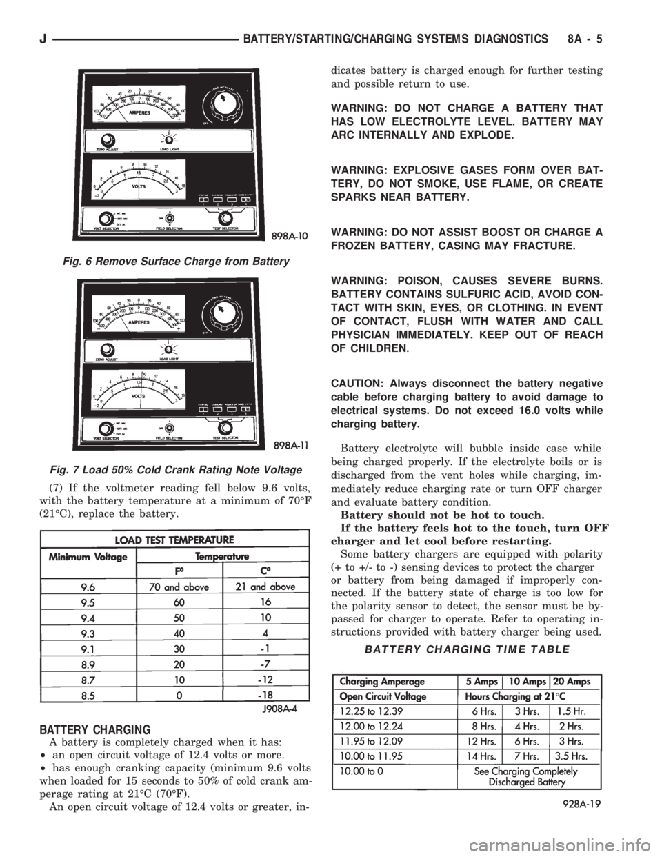
(7) If the voltmeter reading fell below 9.6 volts,
with the battery temperature at a minimum of 70ÉF
(21ÉC), replace the battery.
BATTERY CHARGING
A battery is completely charged when it has:
²an open circuit voltage of 12.4 volts or more.
²has enough cranking capacity (minimum 9.6 volts
when loaded for 15 seconds to 50% of cold crank am-
perage rating at 21ÉC (70ÉF).
An open circuit voltage of 12.4 volts or greater, in-dicates battery is charged enough for further testing
and possible return to use.
WARNING: DO NOT CHARGE A BATTERY THAT
HAS LOW ELECTROLYTE LEVEL. BATTERY MAY
ARC INTERNALLY AND EXPLODE.
WARNING: EXPLOSIVE GASES FORM OVER BAT-
TERY, DO NOT SMOKE, USE FLAME, OR CREATE
SPARKS NEAR BATTERY.
WARNING: DO NOT ASSIST BOOST OR CHARGE A
FROZEN BATTERY, CASING MAY FRACTURE.
WARNING: POISON, CAUSES SEVERE BURNS.
BATTERY CONTAINS SULFURIC ACID, AVOID CON-
TACT WITH SKIN, EYES, OR CLOTHING. IN EVENT
OF CONTACT, FLUSH WITH WATER AND CALL
PHYSICIAN IMMEDIATELY. KEEP OUT OF REACH
OF CHILDREN.
CAUTION: Always disconnect the battery negative
cable before charging battery to avoid damage to
electrical systems. Do not exceed 16.0 volts while
charging battery.
Battery electrolyte will bubble inside case while
being charged properly. If the electrolyte boils or is
discharged from the vent holes while charging, im-
mediately reduce charging rate or turn OFF charger
and evaluate battery condition.
Battery should not be hot to touch.
If the battery feels hot to the touch, turn OFF
charger and let cool before restarting.
Some battery chargers are equipped with polarity
(+ to +/- to -) sensing devices to protect the charger
or battery from being damaged if improperly con-
nected. If the battery state of charge is too low for
the polarity sensor to detect, the sensor must be by-
passed for charger to operate. Refer to operating in-
structions provided with battery charger being used.
Fig. 6 Remove Surface Charge from Battery
Fig. 7 Load 50% Cold Crank Rating Note Voltage
BATTERY CHARGING TIME TABLE
JBATTERY/STARTING/CHARGING SYSTEMS DIAGNOSTICS 8A - 5
Page 283 of 1784
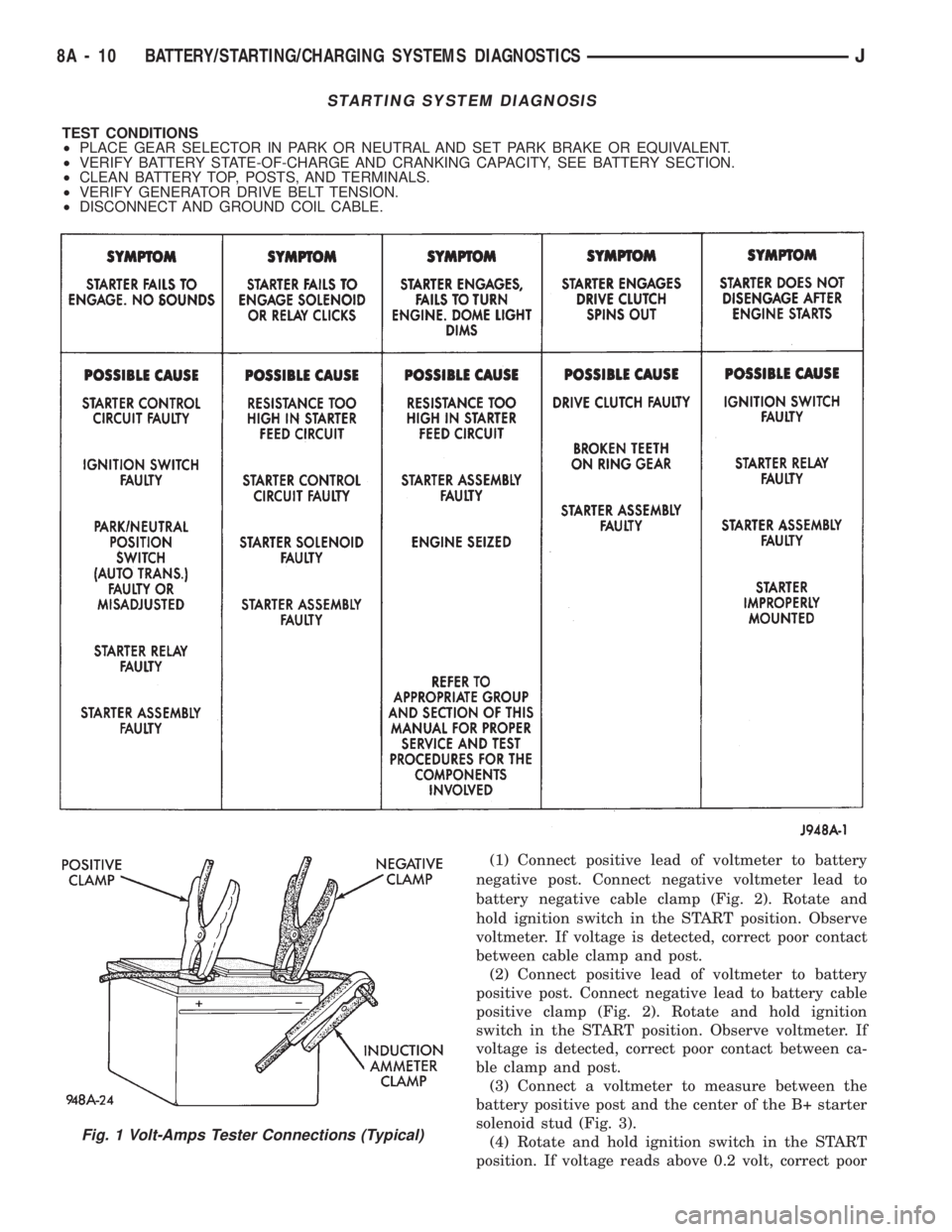
(1) Connect positive lead of voltmeter to battery
negative post. Connect negative voltmeter lead to
battery negative cable clamp (Fig. 2). Rotate and
hold ignition switch in the START position. Observe
voltmeter. If voltage is detected, correct poor contact
between cable clamp and post.
(2) Connect positive lead of voltmeter to battery
positive post. Connect negative lead to battery cable
positive clamp (Fig. 2). Rotate and hold ignition
switch in the START position. Observe voltmeter. If
voltage is detected, correct poor contact between ca-
ble clamp and post.
(3) Connect a voltmeter to measure between the
battery positive post and the center of the B+ starter
solenoid stud (Fig. 3).
(4) Rotate and hold ignition switch in the START
position. If voltage reads above 0.2 volt, correct poor
STARTING SYSTEM DIAGNOSIS
TEST CONDITIONS
²PLACE GEAR SELECTOR IN PARK OR NEUTRAL AND SET PARK BRAKE OR EQUIVALENT.
²VERIFY BATTERY STATE-OF-CHARGE AND CRANKING CAPACITY, SEE BATTERY SECTION.
²CLEAN BATTERY TOP, POSTS, AND TERMINALS.
²VERIFY GENERATOR DRIVE BELT TENSION.
²DISCONNECT AND GROUND COIL CABLE.
Fig. 1 Volt-Amps Tester Connections (Typical)
8A - 10 BATTERY/STARTING/CHARGING SYSTEMS DIAGNOSTICSJ
Page 1113 of 1784
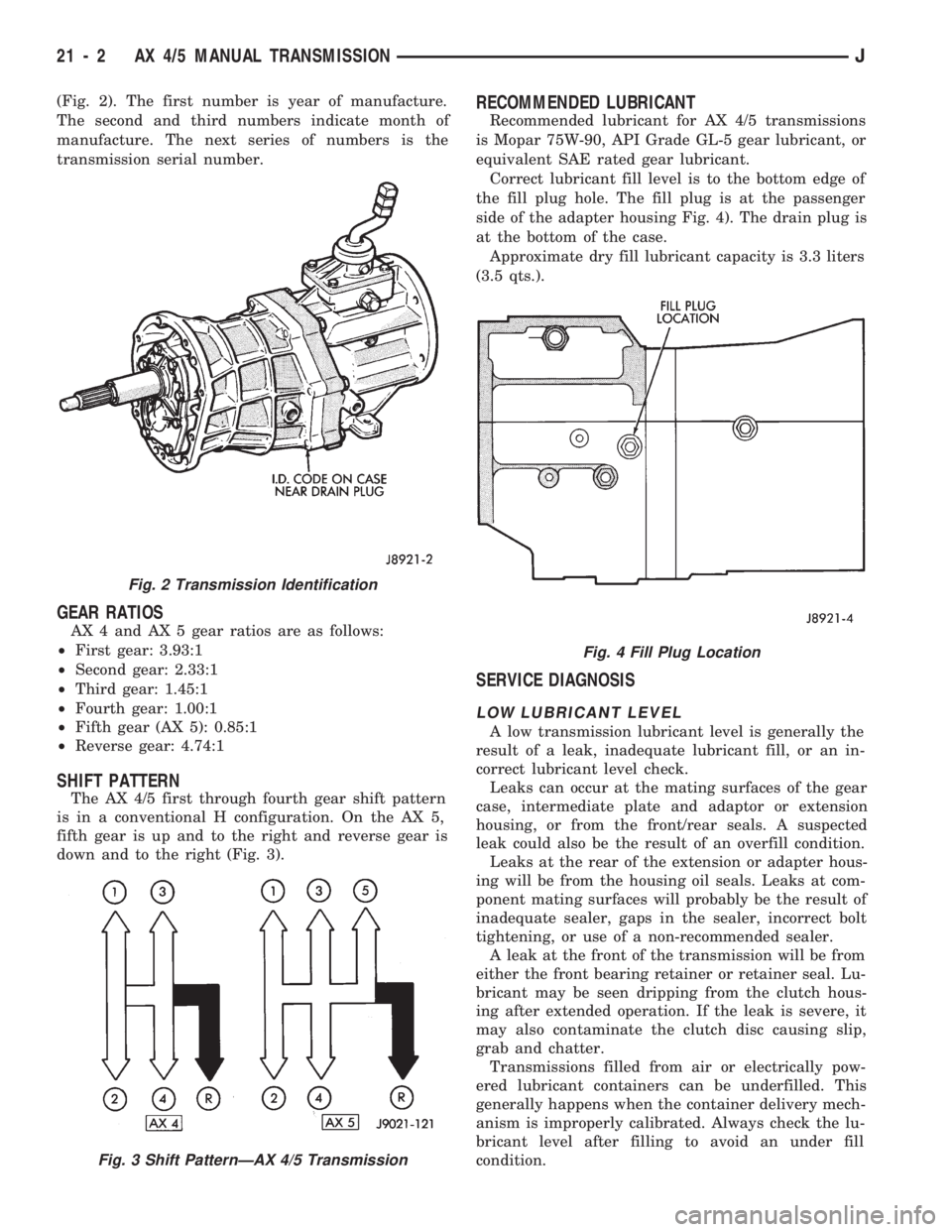
(Fig. 2). The first number is year of manufacture.
The second and third numbers indicate month of
manufacture. The next series of numbers is the
transmission serial number.
GEAR RATIOS
AX 4 and AX 5 gear ratios are as follows:
²First gear: 3.93:1
²Second gear: 2.33:1
²Third gear: 1.45:1
²Fourth gear: 1.00:1
²Fifth gear (AX 5): 0.85:1
²Reverse gear: 4.74:1
SHIFT PATTERN
The AX 4/5 first through fourth gear shift pattern
is in a conventional H configuration. On the AX 5,
fifth gear is up and to the right and reverse gear is
down and to the right (Fig. 3).
RECOMMENDED LUBRICANT
Recommended lubricant for AX 4/5 transmissions
is Mopar 75W-90, API Grade GL-5 gear lubricant, or
equivalent SAE rated gear lubricant.
Correct lubricant fill level is to the bottom edge of
the fill plug hole. The fill plug is at the passenger
side of the adapter housing Fig. 4). The drain plug is
at the bottom of the case.
Approximate dry fill lubricant capacity is 3.3 liters
(3.5 qts.).
SERVICE DIAGNOSIS
LOW LUBRICANT LEVEL
A low transmission lubricant level is generally the
result of a leak, inadequate lubricant fill, or an in-
correct lubricant level check.
Leaks can occur at the mating surfaces of the gear
case, intermediate plate and adaptor or extension
housing, or from the front/rear seals. A suspected
leak could also be the result of an overfill condition.
Leaks at the rear of the extension or adapter hous-
ing will be from the housing oil seals. Leaks at com-
ponent mating surfaces will probably be the result of
inadequate sealer, gaps in the sealer, incorrect bolt
tightening, or use of a non-recommended sealer.
A leak at the front of the transmission will be from
either the front bearing retainer or retainer seal. Lu-
bricant may be seen dripping from the clutch hous-
ing after extended operation. If the leak is severe, it
may also contaminate the clutch disc causing slip,
grab and chatter.
Transmissions filled from air or electrically pow-
ered lubricant containers can be underfilled. This
generally happens when the container delivery mech-
anism is improperly calibrated. Always check the lu-
bricant level after filling to avoid an under fill
condition.
Fig. 2 Transmission Identification
Fig. 3 Shift PatternÐAX 4/5 Transmission
Fig. 4 Fill Plug Location
21 - 2 AX 4/5 MANUAL TRANSMISSIONJ
Page 1144 of 1784
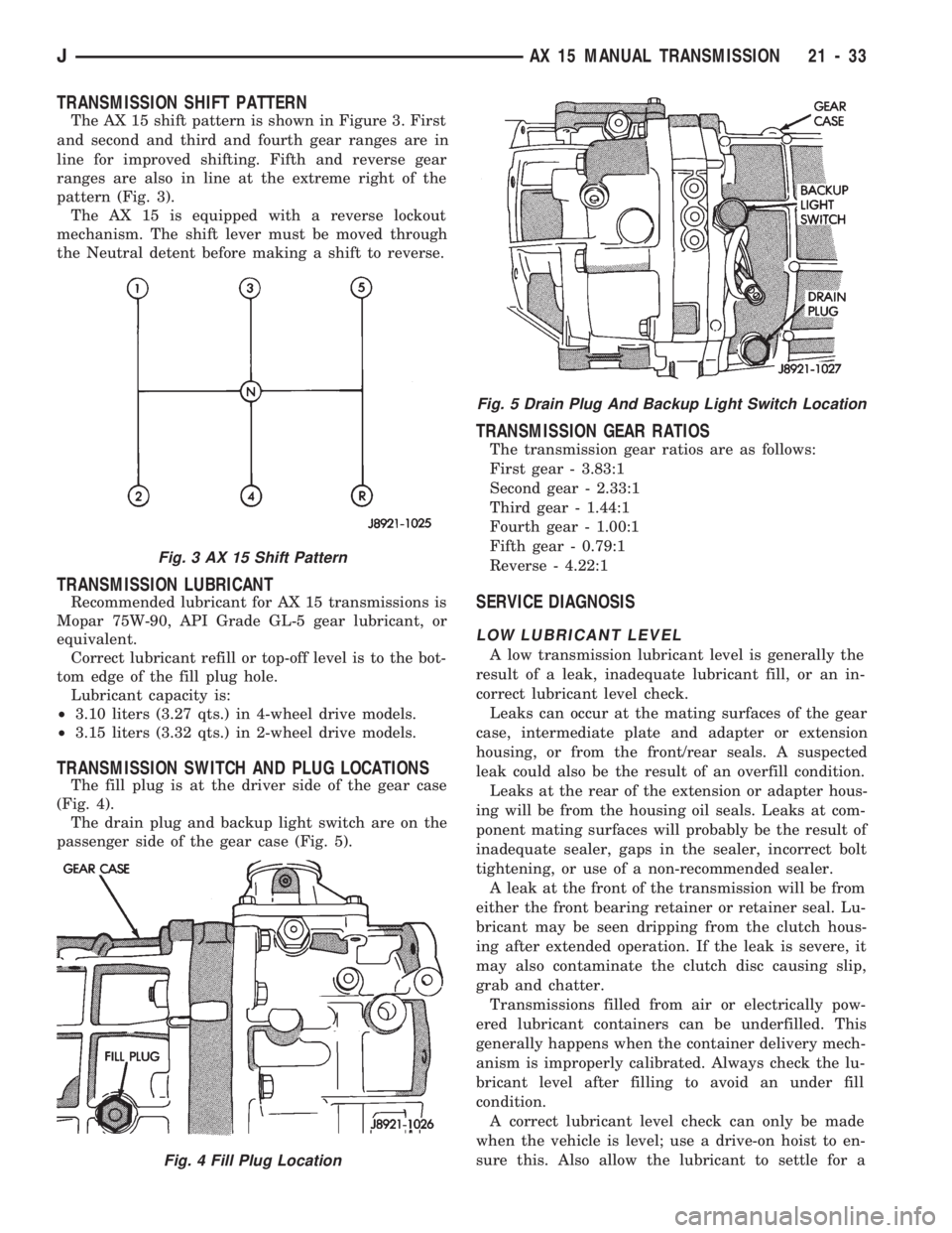
TRANSMISSION SHIFT PATTERN
The AX 15 shift pattern is shown in Figure 3. First
and second and third and fourth gear ranges are in
line for improved shifting. Fifth and reverse gear
ranges are also in line at the extreme right of the
pattern (Fig. 3).
The AX 15 is equipped with a reverse lockout
mechanism. The shift lever must be moved through
the Neutral detent before making a shift to reverse.
TRANSMISSION LUBRICANT
Recommended lubricant for AX 15 transmissions is
Mopar 75W-90, API Grade GL-5 gear lubricant, or
equivalent.
Correct lubricant refill or top-off level is to the bot-
tom edge of the fill plug hole.
Lubricant capacity is:
²3.10 liters (3.27 qts.) in 4-wheel drive models.
²3.15 liters (3.32 qts.) in 2-wheel drive models.
TRANSMISSION SWITCH AND PLUG LOCATIONS
The fill plug is at the driver side of the gear case
(Fig. 4).
The drain plug and backup light switch are on the
passenger side of the gear case (Fig. 5).
TRANSMISSION GEAR RATIOS
The transmission gear ratios are as follows:
First gear - 3.83:1
Second gear - 2.33:1
Third gear - 1.44:1
Fourth gear - 1.00:1
Fifth gear - 0.79:1
Reverse - 4.22:1
SERVICE DIAGNOSIS
LOW LUBRICANT LEVEL
A low transmission lubricant level is generally the
result of a leak, inadequate lubricant fill, or an in-
correct lubricant level check.
Leaks can occur at the mating surfaces of the gear
case, intermediate plate and adapter or extension
housing, or from the front/rear seals. A suspected
leak could also be the result of an overfill condition.
Leaks at the rear of the extension or adapter hous-
ing will be from the housing oil seals. Leaks at com-
ponent mating surfaces will probably be the result of
inadequate sealer, gaps in the sealer, incorrect bolt
tightening, or use of a non-recommended sealer.
A leak at the front of the transmission will be from
either the front bearing retainer or retainer seal. Lu-
bricant may be seen dripping from the clutch hous-
ing after extended operation. If the leak is severe, it
may also contaminate the clutch disc causing slip,
grab and chatter.
Transmissions filled from air or electrically pow-
ered lubricant containers can be underfilled. This
generally happens when the container delivery mech-
anism is improperly calibrated. Always check the lu-
bricant level after filling to avoid an under fill
condition.
A correct lubricant level check can only be made
when the vehicle is level; use a drive-on hoist to en-
sure this. Also allow the lubricant to settle for a
Fig. 3 AX 15 Shift Pattern
Fig. 4 Fill Plug Location
Fig. 5 Drain Plug And Backup Light Switch Location
JAX 15 MANUAL TRANSMISSION 21 - 33
Page 1177 of 1784
30RH/32RH AUTOMATIC TRANSMISSION
INDEX
page page
General Information....................... 66
Parts Interchangeability.................... 66
Recommended Fluid...................... 66
Specifications and Band Adjustments......... 66Torque Converter........................ 66
Transmission Application................... 66
Transmission Controls and Components....... 66
Transmission Identification.................. 66
GENERAL INFORMATION
TRANSMISSION APPLICATION
Chrysler 30RH and 32RH automatic transmissions
are used in XJ/YJ models. Both transmissions are
three speed, automatics with a gear-type oil pump,
two clutches and bands and a planetary gear system
(Fig. 1). The 30RH is used with 2.5L engines and the
32RH is used with 4.0L engines.
TORQUE CONVERTER
A three element, torque converter is used for all
applications. The converter consists of the impeller,
stator, and turbine.
The converter used with all 30RH/32RH transmis-
sions is equipped with a converter clutch. The clutch
is engaged by an electrical solenoid and mechanical
clutch module on the valve body. The solenoid is op-
erated by the powertrain control module.
The impeller is connected to the engine crankshaft
through the front cover which is welded to the impel-
ler. The turbine is splined to the transmission input
shaft and the stator is splined to the transmission re-
action shaft.
The torque converter is a welded assembly and is
not a repairable component. The converter is serviced
as an assembly.
RECOMMENDED FLUID
The recommended (and preferred) fluid for 30RH/
32RH transmissions is Mopar ATF Plus, Type 7176.
Mopar Dexron II can be used but only if ATF Plus
is not available.
Transmission fluid capacity is approximately 17
pints (7.9 liters). This is the approximate amount of
fluid required to fill the transmission and torque con-
verter after overhaul.
TRANSMISSION IDENTIFICATION
The transmission identification numbers are
stamped on the left side of the case just above the oil
pan gasket surface (Fig. 2). The first set of numbers
is the transmission part number. The next set of code
numbers set is the date of build. The final set of code
numbers represents the transmission serial number.
SPECIFICATIONS AND BAND ADJUSTMENTS
Service specifications and torque values are located
at the end of this group. Refer to the specifications
during service operations.
The band adjustment specifications for 1994
transmissions are different. Refer to the front
and rear band adjustment procedures in the In-
Vehicle Service section for details.
PARTS INTERCHANGEABILITY
The 1994 version of the 30RH (A904) transmission
is similar to previous models in appearance only. The
current 30RH is quite different and interchanging
new/old parts is definitely not recommended. Differ-
ent component dimensions, fluid passages, input/out-
put shafts, cases, bands, valve bodies and governor
assemblies are just a few of the changed items. The
32RH transmission is also different from previous
models and the same recommendations apply here as
well.
CAUTION: On YJ models with a 2.5L engine and
30RH transmission, special bolts are used to attach
the driveplate to the crankshaft. These bolts have a
smaller hex head for torque converter clearance.
DO NOT interchange these bolts with similar size
bolts for any reason.
TRANSMISSION CONTROLS AND COMPONENTS
The transmission hydraulic control system per-
forms five basic functions, which are:
²pressure supply
²pressure regulation
²flow control
²clutch/band apply and release
²lubrication
Pressure Supply And Regulation
The oil pump generates the fluid working pressure
needed for operation and lubrication. The pump is
driven by the torque converter. The converter is con-
nected to the engine crankshaft through the drive-
plate.
The pressure regulator valve maintains operating
(line) pressure. The regulator valve is located in the
valve body. The amount of line pressure developed is
21 - 66 30RH/32RH AUTOMATIC TRANSMISSIONJ
Page 1207 of 1784
30RH/32RH IN-VEHICLE SERVICE
INDEX
page page
Checking Fluid Level and Condition........... 96
Front Band Adjustment.................... 99
Gearshift Linkage Adjustment (YJ)............ 96
Governor and Park Gear Service............ 101
Oil Filter Replacement.................... 100
Park Interlock Cable Adjustment (XJ)......... 97
Park Lock Component Replacement......... 102
Park/Neutral Position Switch Service......... 103
Rear Band Adjustment.................... 99
Recommended Fluid...................... 96
Servicing Transmission Cooler Lines and Fittings. 106
Shift Cable Adjustment (XJ)................ 97
Speedometer Service.................... 103
Transmission Cooler Flow Testing........... 106
Transmission Cooler Reverse Flushing....... 105
Transmission Throttle Cable Adjustment (XJ/YJ) . 98
Valve Body Installation................... 101
Valve Body Removal..................... 100
Valve Body Service...................... 100
RECOMMENDED FLUID
The recommended and preferred fluid for 30RH/
32RH transmissions is Mopar ATF Plus, Type 7176.
Mopar Dexron II is acceptable but should only be
used when ATF Plus is not available.
Transmission fluid capacity is approximately 17
pints (7.9 liters). This is the approximate amount of
fluid required to fill the transmission and torque con-
verter after overhaul.
CHECKING FLUID LEVEL AND CONDITION
(1) Position vehicle on flat, level surface. This is
important in obtaining an accurate fluid level check.
(2) To avoid false readings, which could produce
under or over fill condition, do not check level until
fluid is at normal operating temperature.
(3) Shift transmission into Neutral.
(4) Apply parking brakes.
(5) Operate engine at curb idle speed.
WARNING: WHEN PERFORMING UNDERHOOD OP-
ERATIONS WITH THE ENGINE RUNNING, KEEP
YOUR HANDS WELL AWAY FROM HOT OR ROTAT-
ING ENGINE COMPONENTS. DO NOT WEAR
LOOSE ARTICLES OF CLOTHING WHICH COULD
BECOME ENTANGLED IN ENGINE COMPONENTS
OR ACCESSORIES.
(6) Shift transmission through all gear ranges and
back to Neutral (leave engine running).
(7) Clean exterior of dipstick cap and fill tube be-
fore removing transmission dipstick.
(8) Remove dipstick and inspect fluid level.
²Correct level is to FULL mark
²Acceptable level is between ADD and FULL marks
(9) Check fluid condition. Fluid should be dark to
light red in color and free of dirt or debris.
(10) If fluid is discolored or smells burned but
transmission operation was OK, check cooler flow,
flush cooler and lines and change fluid and filter.
Then road test again to confirm proper operation.(11) If fluid is black or dark brown, burned/turned
to sludge, contains large quantities of metal or fric-
tion material particles, transmission will need over-
haul. Especially if problems were evident during
road test and preliminary diagnosis. Fluid cooler
should also be flow tested and flushed if necessary.
GEARSHIFT LINKAGE ADJUSTMENT (YJ)
(1) Check linkage adjustment by starting engine in
Park and Neutral.
(2) Adjustment is OK if engine starts only in park
and Neutral. Adjustment is incorrect if engine starts
in one but not both positions.
(3) If engine starts in any position other than Park
or Neutral, or if engine will not start at all, park/
neutral position switch may be faulty.
(4) Shift transmission into Park.
(5) Raise vehicle.
(6) Check condition of shift rods, bellcrank, bell-
crank brackets and linkage bushings/grommets (Fig.
1). Tighten, repair, replace worn, damaged parts. Do
not attempt adjustment if linkage components are
worn or damaged.
(7) Loosen shift rod trunnion lock bolt or nut. Be
sure upper shift rod slides freely in trunnion (Fig. 1).
Also be sure shift rods and bellcrank rotate freely
and do not bind at any point.
(8) Verify that manual lever is in Park detent
(Fig. 1). Move lever all the way rearward to be sure
it is in Park.
(9) Check for positive engagement of park lock by
attempting to rotate propeller shaft. Shaft will not
turn when park pawl is engaged.
(10) Adjust shift rod trunnion to a obtain free pin
fit in bellcrank arm and tighten trunnion lock bolt or
nut. Prevent shift rod from turning while tightening
bolt or nut. Gearshift linkage lash must be elimi-
nated to obtain proper adjustment. Eliminate lash by
pulling downward on shift rod and pressing upward
on bellcrank.
21 - 96 30RH/32RH IN-VEHICLE SERVICEJ
Page 1445 of 1784
TIRE CHAINS
Tire snow chains may be used on certain models.
Refer to Owner's Manual for more information.
CLEANING OF TIRES
Steam cleaning may be used for cleaning.
DO NOT use gasoline or wire brush for cleaning.
DO NOT use mineral oil or an oil-based solvent.
PRESSURE GAUGES
High-quality, dial-type, air-pressure gauges are
recommended. After checking with the gauge, re-
place valve cap and finger tight.
TIRE INFLATION PRESSURES
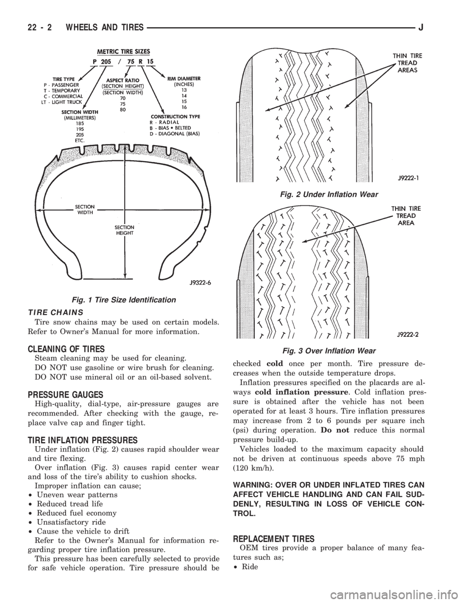
Under inflation (Fig. 2) causes rapid shoulder wear
and tire flexing.
Over inflation (Fig. 3) causes rapid center wear
and loss of the tire's ability to cushion shocks.
Improper inflation can cause;
²Uneven wear patterns
²Reduced tread life
²Reduced fuel economy
²Unsatisfactory ride
²Cause the vehicle to drift
Refer to the Owner's Manual for information re-
garding proper tire inflation pressure.
This pressure has been carefully selected to provide
for safe vehicle operation. Tire pressure should becheckedcoldonce per month. Tire pressure de-
creases when the outside temperature drops.
Inflation pressures specified on the placards are al-
wayscold inflation pressure. Cold inflation pres-
sure is obtained after the vehicle has not been
operated for at least 3 hours. Tire inflation pressures
may increase from 2 to 6 pounds per square inch
(psi) during operation.Do notreduce this normal
pressure build-up.
Vehicles loaded to the maximum capacity should
not be driven at continuous speeds above 75 mph
(120 km/h).
WARNING: OVER OR UNDER INFLATED TIRES CAN
AFFECT VEHICLE HANDLING AND CAN FAIL SUD-
DENLY, RESULTING IN LOSS OF VEHICLE CON-
TROL.
REPLACEMENT TIRES
OEM tires provide a proper balance of many fea-
tures such as;
²Ride
Fig. 1 Tire Size Identification
Fig. 2 Under Inflation Wear
Fig. 3 Over Inflation Wear
22 - 2 WHEELS AND TIRESJ