1994 JEEP CHEROKEE seats
[x] Cancel search: seatsPage 39 of 1784
axle assembly to the frame. The lower arms uses
shims at the frame mount to allow for adjustment of
caster and pinion angle. The suspension arm travel
(jounce or rebound) is limited through the use of rub-
ber bumpers.
Suspension components which use rubber bushings
should be tightened at vehicle ride height. This will
prevent premature failure of the bushing and main-
tain ride comfort. Bushings must never be lubricated.
The coil springs control ride quality and maintain
proper ride height. The coil springs mount up in the
fender shield which is part of the unitized body
bracket. A rubber isolator is located between the top
of the spring and the frame. The bottom of the spring
seats on a axle pad and is retained with a clip.
The shock absorbers dampen jounce and rebound of
the vehicle over various road conditions. The top of
the shock absorbers are bolted to the frame. The bot-
tom of the shocks are bolted to the axle spring
bracket.
The stabilizer bar is used to minimize vehicle front
sway during turns. The spring steel bar helps to con-
trol the vehicle body in relationship to the suspen-
sion. The bar extends across the front underside of
the chassis and connects to the frame rails. Links are
connected from the bar to the axle brackets. Stabi-
lizer bar mounts are isolated by rubber bushings.
The track bar is used to minimize front axle side-
to-side movement. The bar is attached to a frame rail
bracket with a ball stud and isolated with a bushing
at the axle bracket.
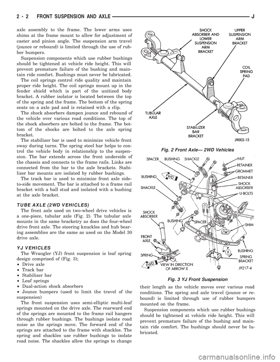
TUBE AXLE (2WD VEHICLES)
The front axle used on two-wheel drive vehicles is
a one-piece, tubular axle (Fig. 2). The tubular axle
mounts in the same bracketry as does the four-wheel
drive front axle. The steering knuckles and hub bear-
ing assemblies are the same as used on the Model 30
drive axle.
YJ VEHICLES
The Wrangler (YJ) front suspension is leaf spring
design comprised of (Fig. 3);
²Drive axle
²Track bar
²Stabilizer bar
²Leaf springs
²Dual-action shock absorbers
²Jounce bumpers (used to limit the travel of the
suspension)
The front suspension uses semi-elliptic multi-leaf
springs mounted on the drive axle. The rearward end
of the springs are mounted to the frame rail hangers
through rubber bushings. The bushings isolate road
noise as the springs move. The forward end of the
springs are attached to the frame with shackles. The
spring and shackles use rubber bushings to isolate
road noise. The shackles allow the springs to changetheir length as the vehicle moves over various road
conditions. The spring and axle travel (jounce or re-
bound) is limited through use of rubber bumpers
mounted on the frame.
Suspension components which use rubber bushings
should be tightened at vehicle ride height. This will
prevent premature failure of the bushing and main-
tain ride comfort. The bushings should never be lu-
bricated.
Fig. 2 Front AxleÐ 2WD Vehicles
Fig. 3 YJ Front Suspension
2 - 2 FRONT SUSPENSION AND AXLEJ
Page 50 of 1784
COIL SPRING
REMOVAL
(1) Raise and support the vehicle. Position a hy-
draulic jack under the axle to support it.
(2) Remove the wheel if necessary.
(3) Mark and disconnect the front propeller shaft
from the axle.
(4) Disconnect the lower suspension arms from the
axle (Fig. 6).
(5) Disconnect the stabilizer bar link and shock ab-
sorber from the axle.
(6) Disconnect the track bar from the frame rail
bracket.
(7) Disconnect the drag link from the pitman arm.
(8) Lower the axle until the spring is free from the
upper mount. Remove the coil spring clip (Fig. 6) and
remove the spring.
(9) Remove the jounce bumper if necessary from
the upper spring mount (Fig. 6).
INSTALLATION
(1) Install the jounce bumper on the upper spring
mount. Tighten the bolt to 42 Nzm (31 ft. lbs.) torque
(Fig. 6).
(2) Position the coil spring on the axle pad. Install
the spring clip and bolt (Fig. 6). Tighten bolt to 21
Nzm (16 ft. lbs.) torque.
(3) Raise the axle into position until the spring
seats in the upper mount.
(4) Connect the stabilizer bar links and shock ab-
sorbers to the axle bracket. Connect the track bar to
the frame rail bracket.
(5) Install the lower suspension arms to the axle.
DO NOT TIGHTEN AT THIS TIME.
(6) Install the front propeller shaft to the axle.
(7) Remove the supports and lower the vehicle.
(8) Tighten lower suspension arms nuts to 115
Nzm (85 ft. lbs.) torque.
YJ FRONT SUSPENSION
INDEX
page page
Leaf Spring............................. 14
Leaf Spring Eye Bushing Replacement........ 15
Service Information....................... 13
Shock Absorber.......................... 14Spring and Shock Diagnosis................ 14
Stabilizer Bar............................ 14
Track Bar.............................. 13
SERVICE INFORMATION
It is important to have the springs supporting
the weight of the vehicle when the track bar fas-
teners are being torqued. If the springs are not
at their normal ride position, vehicle ride com-
fort could be affected along with premature rub-
ber bushing wear.
TRACK BAR
REMOVAL
(1) Raise and support the vehicle.
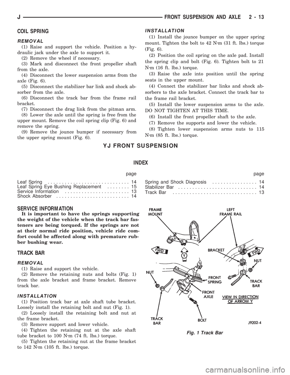
(2) Remove the retaining nuts and bolts (Fig. 1)
from the axle bracket and frame bracket. Remove
track bar.
INSTALLATION
(1) Position track bar at axle shaft tube bracket.
Loosely install the retaining bolt and nut (Fig. 1).
(2) Loosely install the retaining bolt and nut at
the frame bracket.
(3) Remove support and lower vehicle.
(4) Tighten the retaining nut at the axle shaft
tube bracket to 100 Nzm (74 ft. lbs.) torque.
(5) Tighten the retaining nut at the frame bracket
to 142 Nzm (105 ft. lbs.) torque.
Fig. 1 Track Bar
JFRONT SUSPENSION AND AXLE 2 - 13
Page 89 of 1784
(3) Using a brass punch and a hammer, install
lock ring. Carefully tap lock ring clockwise until it
seats against stop on fuel tank.
(4) Connect fuel supply and return hoses to fittings
on fuel pump module. Tighten hose clamps.
(5) Connect fuel pump module electrical harness
connector to main harness connector.
(6) Lower vehicle.
(7) Fill fuel tank. Install fuel tank cap.
(8) Connect negative battery cable.
(9) Start vehicle and inspect for leaks.
REMOVALÐYJ MODELS
The fuel tank must be removed to remove the fuel
pump module.
WARNING: THE FUEL SYSTEM IS UNDER A CON-
STANT PRESSURE (EVEN WITH THE ENGINE OFF).
BEFORE SERVICING THE FUEL PUMP MODULE,
THE FUEL SYSTEM PRESSURE MUST BE RE-
LEASED. REFER TO THE FUEL PRESSURE RE-
LEASE PROCEDURE IN THIS GROUP.
WARNING: EXTINGUISH ALL TOBACCO SMOKING
PRODUCTS BEFORE SERVICING THE FUEL SYS-
TEM. KEEP OPEN FLAME AWAY FROM FUEL SYS-
TEM COMPONENTS.
(1) Remove negative battery cable.
(2) Remove fuel filler cap. Perform the Fuel Pres-
sure Release Procedure as outlined in this group.
(3) Remove fuel tank. Refer to Fuel Tank Remov-
alÐYJ Models.
(4) Remove fuel pump module assembly.
(5) Remove mounting screws. Lift assembly and
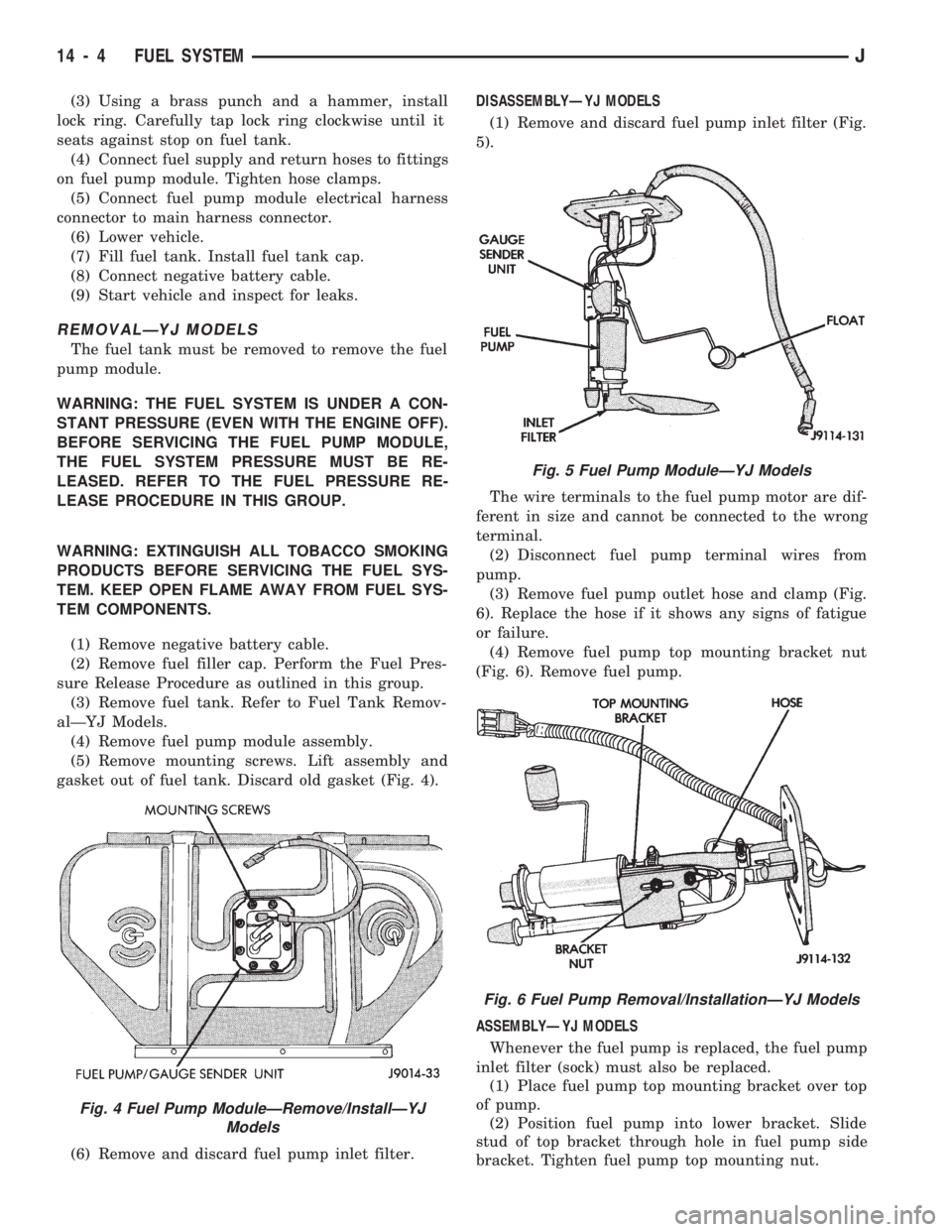
gasket out of fuel tank. Discard old gasket (Fig. 4).
(6) Remove and discard fuel pump inlet filter.DISASSEMBLYÐYJ MODELS
(1) Remove and discard fuel pump inlet filter (Fig.
5).
The wire terminals to the fuel pump motor are dif-
ferent in size and cannot be connected to the wrong
terminal.
(2) Disconnect fuel pump terminal wires from
pump.
(3) Remove fuel pump outlet hose and clamp (Fig.
6). Replace the hose if it shows any signs of fatigue
or failure.
(4) Remove fuel pump top mounting bracket nut
(Fig. 6). Remove fuel pump.
ASSEMBLYÐYJ MODELS
Whenever the fuel pump is replaced, the fuel pump
inlet filter (sock) must also be replaced.
(1) Place fuel pump top mounting bracket over top
of pump.
(2) Position fuel pump into lower bracket. Slide
stud of top bracket through hole in fuel pump side
bracket. Tighten fuel pump top mounting nut.
Fig. 4 Fuel Pump ModuleÐRemove/InstallÐYJ
Models
Fig. 5 Fuel Pump ModuleÐYJ Models
Fig. 6 Fuel Pump Removal/InstallationÐYJ Models
14 - 4 FUEL SYSTEMJ
Page 100 of 1784
INSTALLATIONÐYJ MODELS
(1) Place tank into skid plate. Wrap straps around
tank with strap bolts inserted through holes in skid
plate. Tighten strap nuts to 7.3 Nzm (65 in. lbs.) torque.
(2) Raise skid plate/fuel tank until gauge sender wire
connector can be connected to harness connector.
(3) Finish raising skid plate/fuel tank assembly
into position. Tighten mounting nuts to 16 Nzm (12
ft. lbs.) torque. Remove transmission jack.
(4) Connect fuel fill hose and fill vent hose to filler
neck. Tighten hose clamps.
(5) Connect vent hose to vent tube.
(6) Connect fuel supply hose to the supply tube and
fuel return hose to return tube. Tighten hose clamps.
(7) Install fuel filler neck shroud with push clips.
(8) Lower vehicle.
(9) Fill fuel tank. Install filler cap.
(10) Connect negative battery cable to battery.
(11) Start vehicle and inspect for leaks.
FUEL GAUGE SENDING UNIT
The fuel gauge sending unit is attached to the fuel
pump module. Refer to Fuel Pump Module in the
Fuel Delivery System section of this group.
FUEL TANK PRESSURE RELIEF/ROLLOVER VALVE
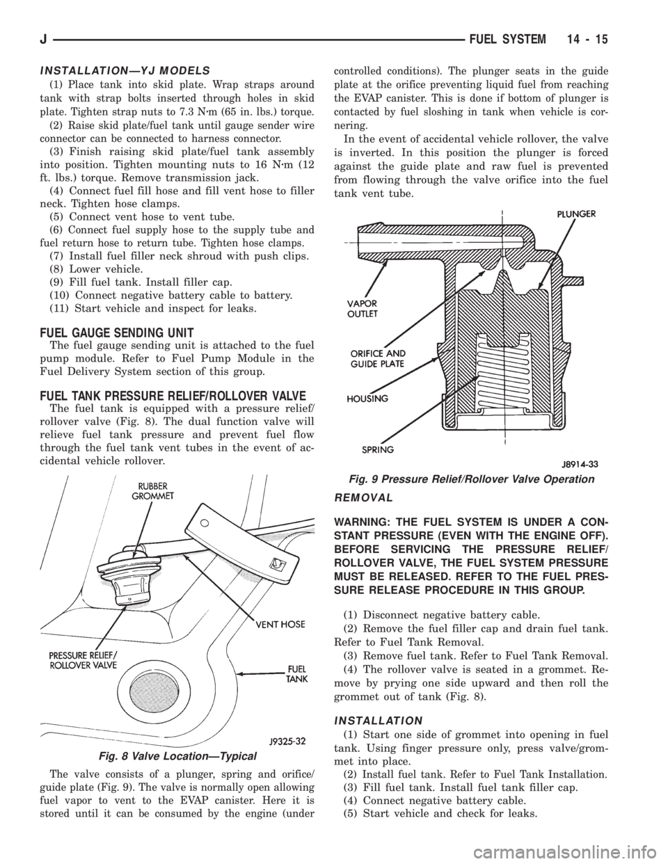
The fuel tank is equipped with a pressure relief/
rollover valve (Fig. 8). The dual function valve will
relieve fuel tank pressure and prevent fuel flow
through the fuel tank vent tubes in the event of ac-
cidental vehicle rollover.
The valve consists of a plunger, spring and orifice/
guide plate (Fig. 9). The valve is normally open allowing
fuel vapor to vent to the EVAP canister. Here it is
stored until it can be consumed by the engine (undercontrolled conditions). The plunger seats in the guide
plate at the orifice preventing liquid fuel from reaching
the EVAP canister. This is done if bottom of plunger is
contacted by fuel sloshing in tank when vehicle is cor-
nering.
In the event of accidental vehicle rollover, the valve
is inverted. In this position the plunger is forced
against the guide plate and raw fuel is prevented
from flowing through the valve orifice into the fuel
tank vent tube.
REMOVAL
WARNING: THE FUEL SYSTEM IS UNDER A CON-
STANT PRESSURE (EVEN WITH THE ENGINE OFF).
BEFORE SERVICING THE PRESSURE RELIEF/
ROLLOVER VALVE, THE FUEL SYSTEM PRESSURE
MUST BE RELEASED. REFER TO THE FUEL PRES-
SURE RELEASE PROCEDURE IN THIS GROUP.
(1) Disconnect negative battery cable.
(2) Remove the fuel filler cap and drain fuel tank.
Refer to Fuel Tank Removal.
(3) Remove fuel tank. Refer to Fuel Tank Removal.
(4) The rollover valve is seated in a grommet. Re-
move by prying one side upward and then roll the
grommet out of tank (Fig. 8).
INSTALLATION
(1) Start one side of grommet into opening in fuel
tank. Using finger pressure only, press valve/grom-
met into place.
(2) Install fuel tank. Refer to Fuel Tank Installation.
(3) Fill fuel tank. Install fuel tank filler cap.
(4) Connect negative battery cable.
(5) Start vehicle and check for leaks.
Fig. 8 Valve LocationÐTypical
Fig. 9 Pressure Relief/Rollover Valve Operation
JFUEL SYSTEM 14 - 15
Page 306 of 1784

OVERHEAD CONSOLE
CONTENTS
page page
COMPASS REPAIR PROCEDURES.......... 4
CONSOLE REPAIR PROCEDURES........... 6
DESCRIPTION........................... 1DIAGNOSTIC PROCEDURES............... 1
THERMOMETER AND SENSOR SYSTEM REPAIR
PROCEDURES......................... 6
DESCRIPTION
The overhead console includes:
²a compass/temperature display
²reading and courtesy lights for the front and rear
seats
²the receiver for the keyless entry system
²storage compartment for remote garage door
opener
²storage compartment for sunglasses.
COMPASS
The compass will display the direction the vehicle
is pointed, using the eight major compass headings
(Examples: North is ``N'', Northeast is ``NE''). It does
not display the headings in actual degrees. The dis-
play is turned on/off using the TEMP/COMP button
on the left of the display.
The compass is a self calibrating unit that should
not require recalibration. The only calibration that
may prove necessary is to drive the vehicle in 3 com-
plete circles, on level ground, in not less than 48 sec-
onds. This will ``reorient'' the unit to its vehicle. The
unit also will compensate for magnetism the vehicle
may acquire during its life. Care should be used to
avoid putting anything magnetic on the roof of the
vehicle.
The unit can compensate for some magnetic fields
in the body. The use of magnetic attachments like
antenna mounts or repair order ``hats'' placed di-
rectly on the roof can exceed the compensation abil-
ity of the unit. Magnetic bit drivers used on the
fasteners to hold the assembly to the roof header can
also affect operation. If the vehicle roof should be-
come magnetized, then the degaussing and calibra-
tion procedures may be required to restore proper
operation.
If the compass functions but accuracy is suspect, it
may be necessary to perform a variation adjustment.
This procedure allows the unit to accommodate vari-
ations in the earth's magnetic field strength based on
geographic location.
If the compass has blanked out and only CAL
appears, degaussing may be necessary to re-
move residual magnetic fields.
THERMOMETER
The ambient temperature display can be changed
from Fahrenheit to Celsius using the U.S./METRIC
button on the right of the display. The temperature
reported is not an instant reading of conditions but
an average temperature. It may take the unit several
minutes to react to a major change such as driving
out of a heated garage into winter temperatures.
When the ignition switch is turned OFF, the last
displayed temperature reading stays in memory.
When the ignition switch is turned ON again the
thermometer will display the memory temperature
for one minute; then update the display to the actual
temperature within five minutes.
READING AND COURTESY LAMPS
All reading and courtesy lamps in the overhead
console are activated by the door courtesy circuit.
When all four doors and the liftgate are closed the
lamps can be activated by depressing the correspond-
ing lens. When any door or the liftgate is open, the
switches are disabled. They will not turn the lamps
off.
MAP AND COURTESY LAMPS
These lamps offer several unique features. Both the
map and courtesy lamps can be turned on with the
integral ``Soft Touch'' switch. Pushing this switch en-
ergizes an electrical circuit, which in turn directs
power to the light. The map lamps are unaffected by
the door switches, while the courtesy lamps are
turned on with the opening of any door. When any
door is open, the ``Soft Touch'' switches are disabled,
you cannot turn the lights off with these switches.
DIAGNOSTIC PROCEDURES
Follow the appropriate diagnostic flow chart:
²Chart 1 describes the procedures for compass and
display problems.
²Chart 2 describes the procedures for illumination
lamp problems.
²Chart 3 describes the procedures for outside tem-
perature measuring problems.
JOVERHEAD CONSOLE 8C - 1
Page 336 of 1784
INSTALLATION
(1) Install coolant temperature sensor into the
thermostat housing. Tighten to 28 Nzm (21 ft. lbs.)
torque.
(2) Connect the wire connector.
(3) Fill the cooling system. Refer to group 7, Cool-
ing System.
DISTRIBUTOR
All distributors contain an internal oil seal that
prevents oil from entering the distributor housing.
The seal is not serviceable.
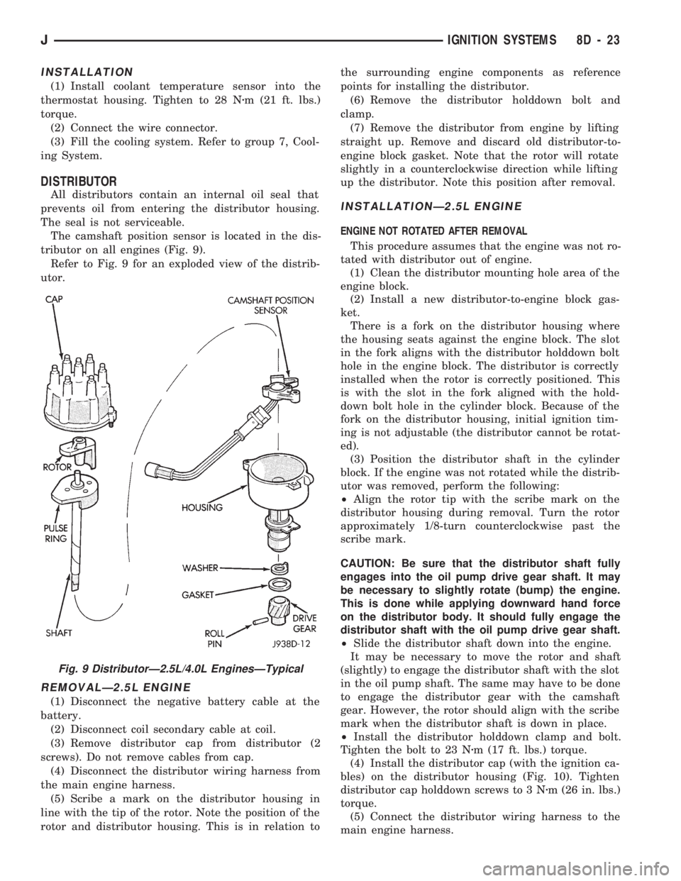
The camshaft position sensor is located in the dis-
tributor on all engines (Fig. 9).
Refer to Fig. 9 for an exploded view of the distrib-
utor.
REMOVALÐ2.5L ENGINE
(1) Disconnect the negative battery cable at the
battery.
(2) Disconnect coil secondary cable at coil.
(3) Remove distributor cap from distributor (2
screws). Do not remove cables from cap.
(4) Disconnect the distributor wiring harness from
the main engine harness.
(5) Scribe a mark on the distributor housing in
line with the tip of the rotor. Note the position of the
rotor and distributor housing. This is in relation tothe surrounding engine components as reference
points for installing the distributor.
(6) Remove the distributor holddown bolt and
clamp.
(7) Remove the distributor from engine by lifting
straight up. Remove and discard old distributor-to-
engine block gasket. Note that the rotor will rotate
slightly in a counterclockwise direction while lifting
up the distributor. Note this position after removal.
INSTALLATIONÐ2.5L ENGINE
ENGINE NOT ROTATED AFTER REMOVAL
This procedure assumes that the engine was not ro-
tated with distributor out of engine.
(1) Clean the distributor mounting hole area of the
engine block.
(2) Install a new distributor-to-engine block gas-
ket.
There is a fork on the distributor housing where
the housing seats against the engine block. The slot
in the fork aligns with the distributor holddown bolt
hole in the engine block. The distributor is correctly
installed when the rotor is correctly positioned. This
is with the slot in the fork aligned with the hold-
down bolt hole in the cylinder block. Because of the
fork on the distributor housing, initial ignition tim-
ing is not adjustable (the distributor cannot be rotat-
ed).
(3) Position the distributor shaft in the cylinder
block. If the engine was not rotated while the distrib-
utor was removed, perform the following:
²Align the rotor tip with the scribe mark on the
distributor housing during removal. Turn the rotor
approximately 1/8-turn counterclockwise past the
scribe mark.
CAUTION: Be sure that the distributor shaft fully
engages into the oil pump drive gear shaft. It may
be necessary to slightly rotate (bump) the engine.
This is done while applying downward hand force
on the distributor body. It should fully engage the
distributor shaft with the oil pump drive gear shaft.
²Slide the distributor shaft down into the engine.
It may be necessary to move the rotor and shaft
(slightly) to engage the distributor shaft with the slot
in the oil pump shaft. The same may have to be done
to engage the distributor gear with the camshaft
gear. However, the rotor should align with the scribe
mark when the distributor shaft is down in place.
²Install the distributor holddown clamp and bolt.
Tighten the bolt to 23 Nzm (17 ft. lbs.) torque.
(4) Install the distributor cap (with the ignition ca-
bles) on the distributor housing (Fig. 10). Tighten
distributor cap holddown screws to 3 Nzm (26 in. lbs.)
torque.
(5) Connect the distributor wiring harness to the
main engine harness.
Fig. 9 DistributorÐ2.5L/4.0L EnginesÐTypical
JIGNITION SYSTEMS 8D - 23
Page 337 of 1784
CAUTION: Do not puncture the spark plug cables or
boots to make the connection. Use proper adapters.
(6) Connect battery cable to battery.
ENGINE ROTATED AFTER REMOVAL
There is a fork on the distributor housing where
the housing seats against the engine block. The slot
in the fork aligns with the hole for the distributor
holddown bolt in the engine block. The distributor is
correctly installed when the rotor is correctly posi-
tioned. This is when the slot in the fork is aligned
with the hole for the distributor holddown bolt in the
cylinder block. Because of the fork on the distributor
housing, initial ignition timing is not adjustable (the
distributor cannot be rotated).
(1) If the engine was rotated while the distributor
was removed, it will be necessary to establish timing
according to following procedure:
²Remove the No. 1 spark plug. Hold a finger over
the spark plug hole and rotate the engine until com-
pression pressure is felt. Slowly continue to rotate
the engine. Do this until the timing index on vibra-
tion damper pulley aligns with top dead center (TDC)mark (0 degree) on timing degree scale. Always ro-
tate the engine in direction of normal rotation. Do
not turn the engine backward to align the timing
marks.
²Using a flat blade screwdriver, rotate the oil pump
gear. Do this to position the gear slot on the oil
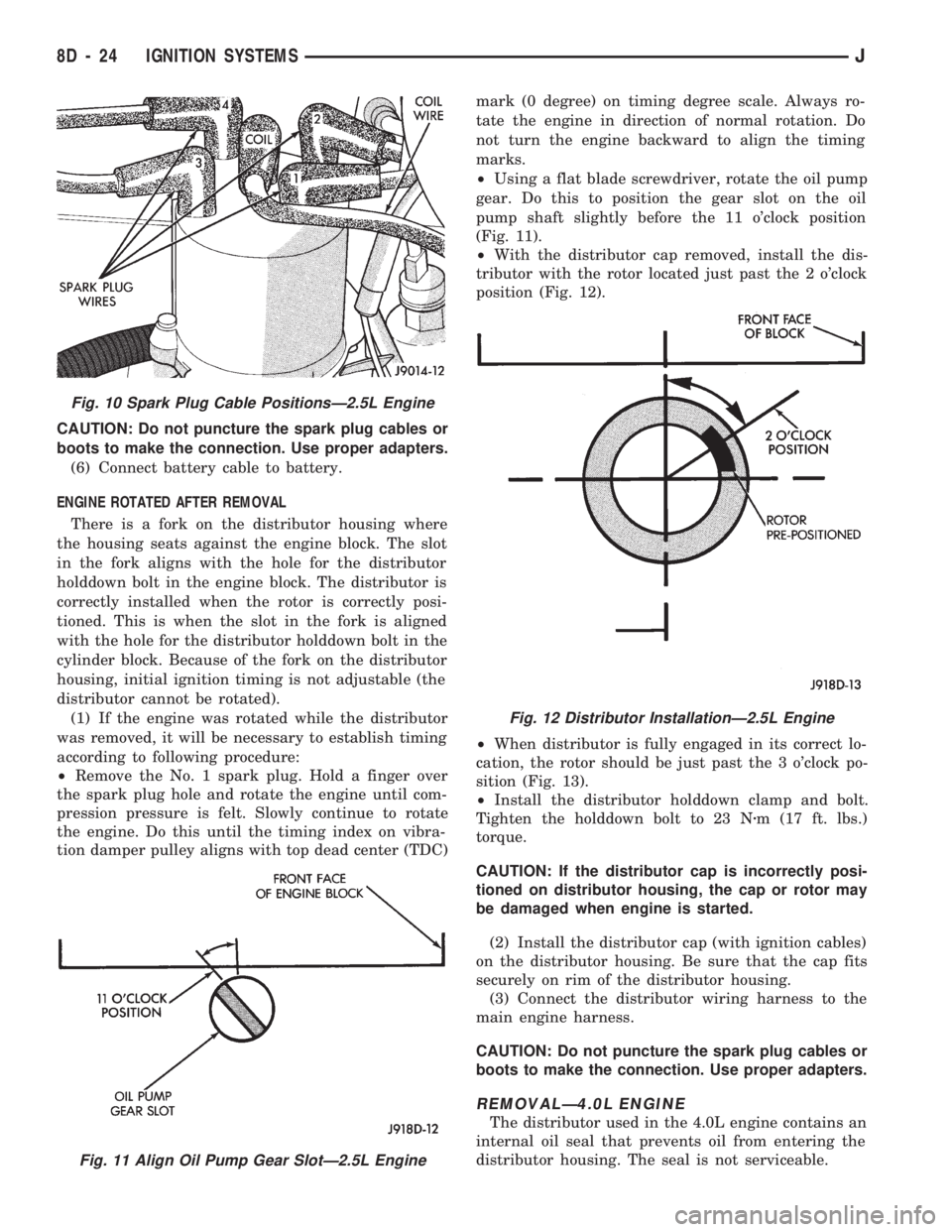
pump shaft slightly before the 11 o'clock position
(Fig. 11).
²With the distributor cap removed, install the dis-
tributor with the rotor located just past the 2 o'clock
position (Fig. 12).
²When distributor is fully engaged in its correct lo-
cation, the rotor should be just past the 3 o'clock po-
sition (Fig. 13).
²Install the distributor holddown clamp and bolt.
Tighten the holddown bolt to 23 Nzm (17 ft. lbs.)
torque.
CAUTION: If the distributor cap is incorrectly posi-
tioned on distributor housing, the cap or rotor may
be damaged when engine is started.
(2) Install the distributor cap (with ignition cables)
on the distributor housing. Be sure that the cap fits
securely on rim of the distributor housing.
(3) Connect the distributor wiring harness to the
main engine harness.
CAUTION: Do not puncture the spark plug cables or
boots to make the connection. Use proper adapters.
REMOVALÐ4.0L ENGINE
The distributor used in the 4.0L engine contains an
internal oil seal that prevents oil from entering the
distributor housing. The seal is not serviceable.
Fig. 11 Align Oil Pump Gear SlotÐ2.5L Engine
Fig. 10 Spark Plug Cable PositionsÐ2.5L Engine
Fig. 12 Distributor InstallationÐ2.5L Engine
8D - 24 IGNITION SYSTEMSJ
Page 339 of 1784
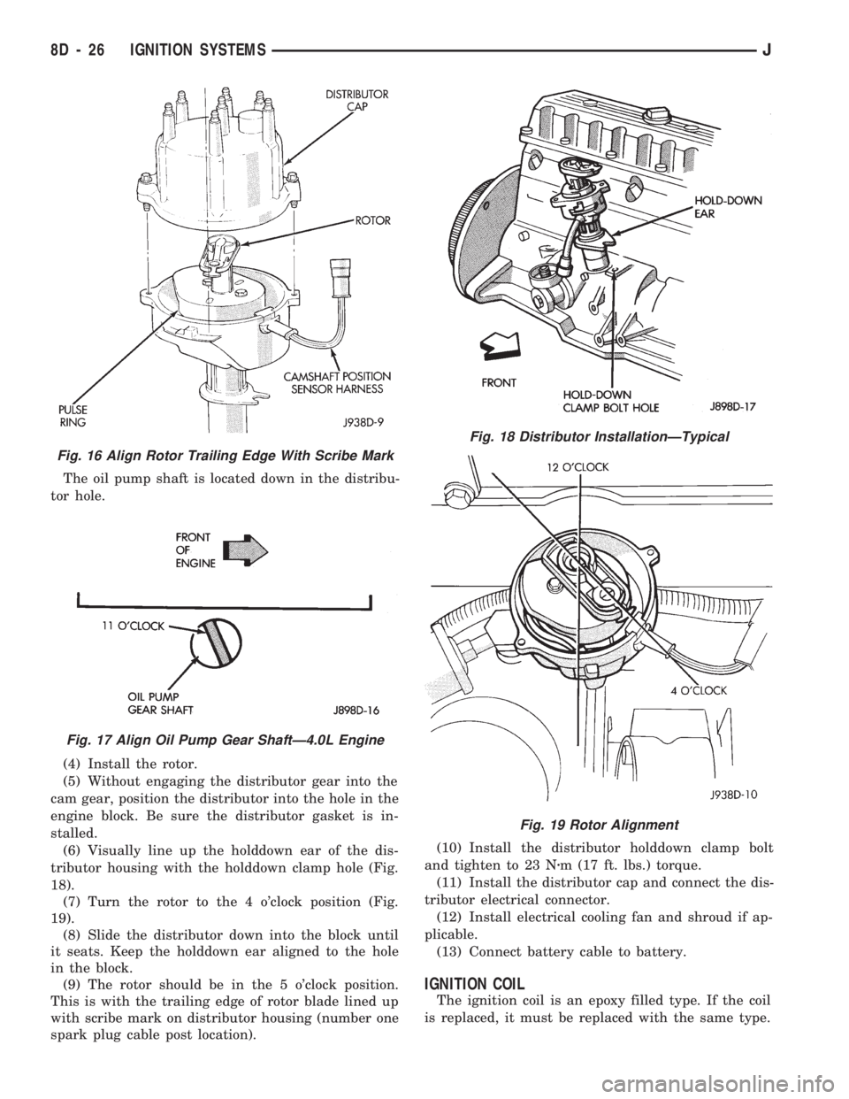
The oil pump shaft is located down in the distribu-
tor hole.
(4) Install the rotor.
(5) Without engaging the distributor gear into the
cam gear, position the distributor into the hole in the
engine block. Be sure the distributor gasket is in-
stalled.
(6) Visually line up the holddown ear of the dis-
tributor housing with the holddown clamp hole (Fig.
18).
(7) Turn the rotor to the 4 o'clock position (Fig.
19).
(8) Slide the distributor down into the block until
it seats. Keep the holddown ear aligned to the hole
in the block.
(9) The rotor should be in the 5 o'clock position.
This is with the trailing edge of rotor blade lined up
with scribe mark on distributor housing (number one
spark plug cable post location).(10) Install the distributor holddown clamp bolt
and tighten to 23 Nzm (17 ft. lbs.) torque.
(11) Install the distributor cap and connect the dis-
tributor electrical connector.
(12) Install electrical cooling fan and shroud if ap-
plicable.
(13) Connect battery cable to battery.
IGNITION COIL
The ignition coil is an epoxy filled type. If the coil
is replaced, it must be replaced with the same type.
Fig. 16 Align Rotor Trailing Edge With Scribe Mark
Fig. 17 Align Oil Pump Gear ShaftÐ4.0L Engine
Fig. 18 Distributor InstallationÐTypical
Fig. 19 Rotor Alignment
8D - 26 IGNITION SYSTEMSJ