1994 JEEP CHEROKEE automatic transmission fluid
[x] Cancel search: automatic transmission fluidPage 1217 of 1784
condenser. The auxiliary cooler is a serviceable com-
ponent and can be repaired if necessary.
The main and auxiliary coolers should be thor-
oughly reverse flushed if a transmission failure
contaminates the fluid. Reverse flushing the cooler
and lines will prevent sludge and particles from
flowing back into the transmission after repair.
The same flushing procedure is used for main and
auxiliary coolers. Pressure equipment is preferred for
reverse flushing. However, reverse flushing can be
performed using hand operated equipment as de-
scribed in the following procedure.
REVERSE FLUSHING PROCEDURE
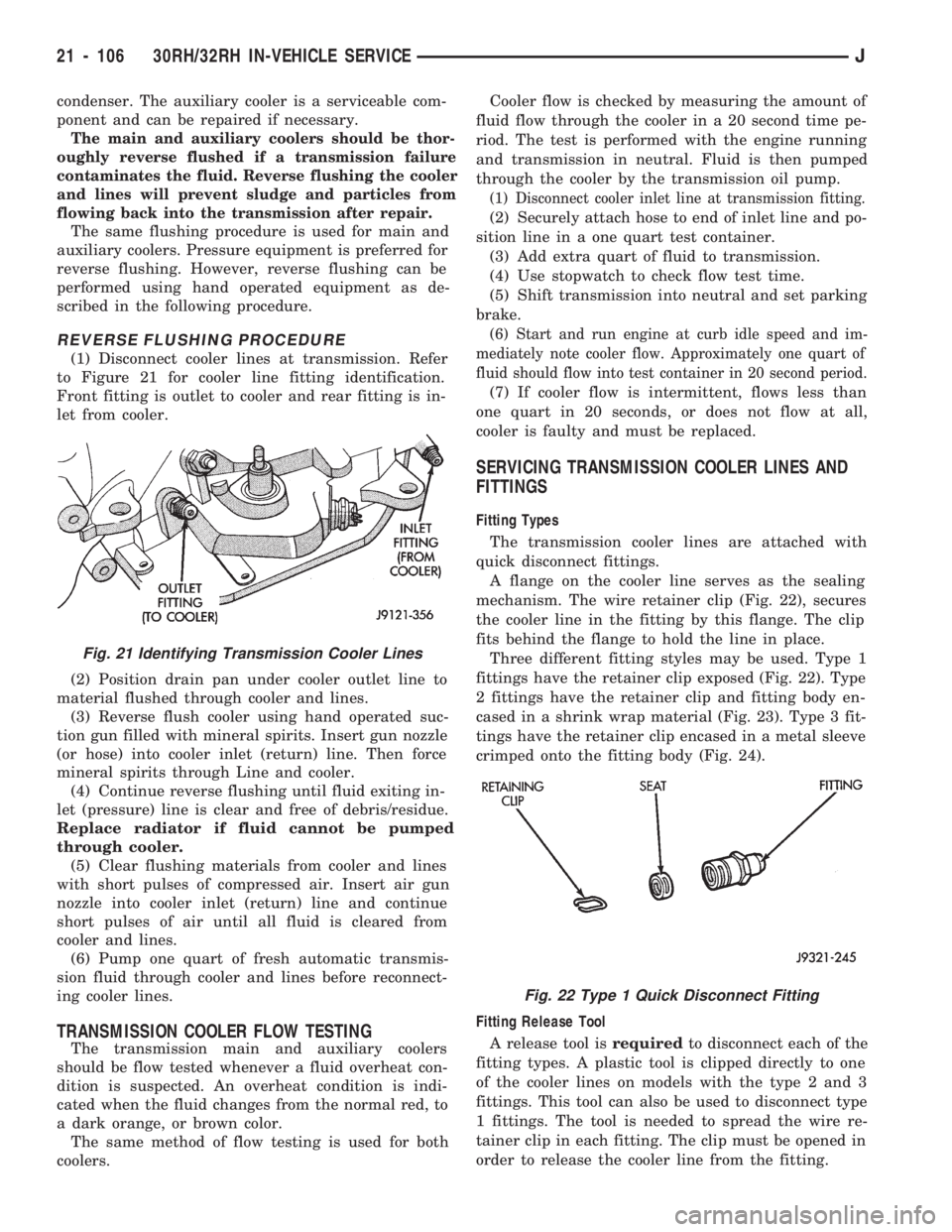
(1) Disconnect cooler lines at transmission. Refer
to Figure 21 for cooler line fitting identification.
Front fitting is outlet to cooler and rear fitting is in-
let from cooler.
(2) Position drain pan under cooler outlet line to
material flushed through cooler and lines.
(3) Reverse flush cooler using hand operated suc-
tion gun filled with mineral spirits. Insert gun nozzle
(or hose) into cooler inlet (return) line. Then force
mineral spirits through Line and cooler.
(4) Continue reverse flushing until fluid exiting in-
let (pressure) line is clear and free of debris/residue.
Replace radiator if fluid cannot be pumped
through cooler.
(5) Clear flushing materials from cooler and lines
with short pulses of compressed air. Insert air gun
nozzle into cooler inlet (return) line and continue
short pulses of air until all fluid is cleared from
cooler and lines.
(6) Pump one quart of fresh automatic transmis-
sion fluid through cooler and lines before reconnect-
ing cooler lines.
TRANSMISSION COOLER FLOW TESTING
The transmission main and auxiliary coolers
should be flow tested whenever a fluid overheat con-
dition is suspected. An overheat condition is indi-
cated when the fluid changes from the normal red, to
a dark orange, or brown color.
The same method of flow testing is used for both
coolers.Cooler flow is checked by measuring the amount of
fluid flow through the cooler in a 20 second time pe-
riod. The test is performed with the engine running
and transmission in neutral. Fluid is then pumped
through the cooler by the transmission oil pump.
(1) Disconnect cooler inlet line at transmission fitting.
(2) Securely attach hose to end of inlet line and po-
sition line in a one quart test container.
(3) Add extra quart of fluid to transmission.
(4) Use stopwatch to check flow test time.
(5) Shift transmission into neutral and set parking
brake.
(6) Start and run engine at curb idle speed and im-
mediately note cooler flow. Approximately one quart of
fluid should flow into test container in 20 second period.
(7) If cooler flow is intermittent, flows less than
one quart in 20 seconds, or does not flow at all,
cooler is faulty and must be replaced.
SERVICING TRANSMISSION COOLER LINES AND
FITTINGS
Fitting Types
The transmission cooler lines are attached with
quick disconnect fittings.
A flange on the cooler line serves as the sealing
mechanism. The wire retainer clip (Fig. 22), secures
the cooler line in the fitting by this flange. The clip
fits behind the flange to hold the line in place.
Three different fitting styles may be used. Type 1
fittings have the retainer clip exposed (Fig. 22). Type
2 fittings have the retainer clip and fitting body en-
cased in a shrink wrap material (Fig. 23). Type 3 fit-
tings have the retainer clip encased in a metal sleeve
crimped onto the fitting body (Fig. 24).
Fitting Release Tool
A release tool isrequiredto disconnect each of the
fitting types. A plastic tool is clipped directly to one
of the cooler lines on models with the type 2 and 3
fittings. This tool can also be used to disconnect type
1 fittings. The tool is needed to spread the wire re-
tainer clip in each fitting. The clip must be opened in
order to release the cooler line from the fitting.
Fig. 21 Identifying Transmission Cooler Lines
Fig. 22 Type 1 Quick Disconnect Fitting
21 - 106 30RH/32RH IN-VEHICLE SERVICEJ
Page 1272 of 1784
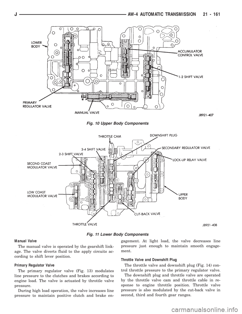
Manual Valve
The manual valve is operated by the gearshift link-
age. The valve diverts fluid to the apply circuits ac-
cording to shift lever position.
Primary Regulator Valve
The primary regulator valve (Fig. 13) modulates
line pressure to the clutches and brakes according to
engine load. The valve is actuated by throttle valve
pressure.
During high load operation, the valve increases line
pressure to maintain positive clutch and brake en-gagement. At light load, the valve decreases line
pressure just enough to maintain smooth engage-
ment.
Throttle Valve and Downshift Plug
The throttle valve and downshift plug (Fig. 14) con-
trol throttle pressure to the primary regulator valve.
The downshift plug and throttle valve are operated
by the throttle valve cam and throttle cable in re-
sponse to engine throttle position. Throttle valve
pressure is also modulated by the cut-back valve in
second, third and fourth gear ranges.
Fig. 11 Lower Body Components
Fig. 10 Upper Body Components
JAW-4 AUTOMATIC TRANSMISSION 21 - 161
Page 1274 of 1784
upward exposing the drain port. Excess pressure
then bleeds off as needed. As pressure drops, spring
tension moves the valve downward closing the drain
port.
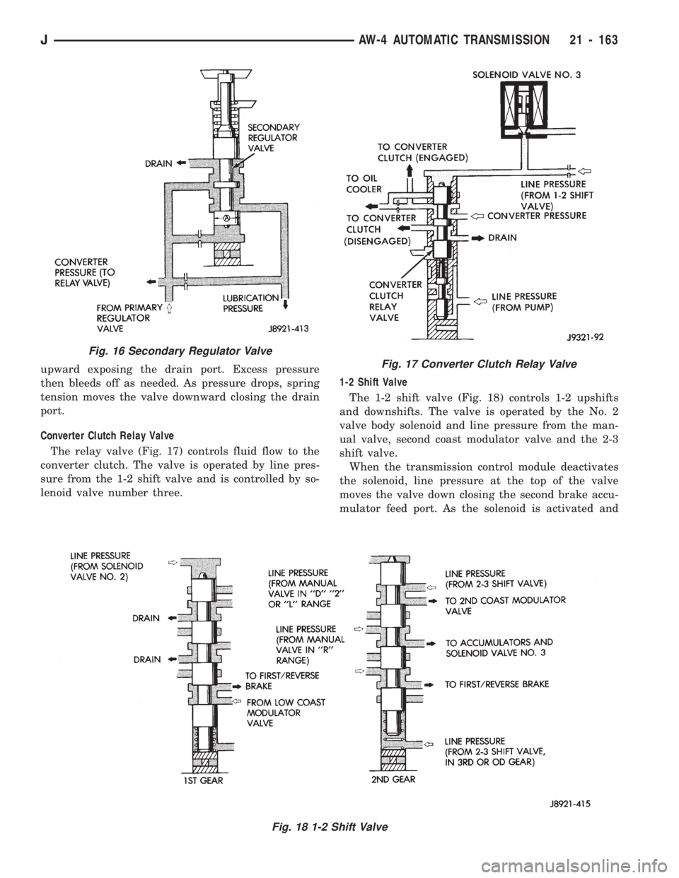
Converter Clutch Relay Valve
The relay valve (Fig. 17) controls fluid flow to the
converter clutch. The valve is operated by line pres-
sure from the 1-2 shift valve and is controlled by so-
lenoid valve number three.1-2 Shift Valve
The 1-2 shift valve (Fig. 18) controls 1-2 upshifts
and downshifts. The valve is operated by the No. 2
valve body solenoid and line pressure from the man-
ual valve, second coast modulator valve and the 2-3
shift valve.
When the transmission control module deactivates
the solenoid, line pressure at the top of the valve
moves the valve down closing the second brake accu-
mulator feed port. As the solenoid is activated and
Fig. 16 Secondary Regulator Valve
Fig. 18 1-2 Shift Valve
Fig. 17 Converter Clutch Relay Valve
JAW-4 AUTOMATIC TRANSMISSION 21 - 163
Page 1298 of 1784
TRANSMISSION COOLER SERVICE
Main Cooler
The transmission main cooler is located in the ra-
diator. The main cooler can be flushed when neces-
sary, however, the cooler is not a repairable
component. If the cooler is damaged, plugged, or
leaking, the radiator will have to be replaced.
Auxiliary Cooler
The auxiliary cooler is mounted in front of the ra-
diator at the driver side of the vehicle (Fig. 48). The
cooler can be flushed when necessary, while mounted
in the vehicle. The cooler can also be removed for ac-
cess, repair, or replacement as needed.
The main and auxiliary coolers should both be
flushed whenever a transmission or converter clutch
malfunction generates sludge, debris, or particles of
clutch friction material.
Cooler Service
The main cooler (and radiator) and the auxiliary
cooler can be removed for service or access to other
components. Auxiliary cooler removal requires that
the front bumper and radiator support be removed
for access to the cooler lines and attaching bracket.
REVERSE FLUSHING MAIN AND AUXILIARY
COOLERS AND COOLER LINES
Reverse flushing the cooler and lines will prevent
sludge and particles from flowing back into the
transmission after repair. The flushing procedure ap-
plies to standard (in-radiator) coolers and auxiliary
coolers equally.
Pressure equipment is preferred for reverse flush-
ing. However, reverse flushing can be performed us-
ing hand operated equipment as described in the
following procedure.
(1) Disconnect cooler lines at transmission and at
auxiliary cooler (Figs. 48 and 49).
(2) Position drain pan under cooler line to catch
material flushed through coolers and lines.
(3) Reverse flush each cooler using hand operated
suction gun filled with mineral spirits. Insert gun
nozzle (or hose) into cooler inlet (return) line. Then
force mineral spirits through into line and through
cooler.(4) Continue reverse flushing until fluid exiting in-
let (pressure) line is clear and free of debris/residue.
(5) Replace radiator if fluid cannot be pumped
through main cooler. Replace auxiliary cooler if leaks
are evident, or if fluid cannot be pumped through it.
(6) Clear flushing materials from coolers and lines
with short pulses of compressed air. Insert air gun
nozzle into cooler inlet (return) line and continue
short pulses of air until all fluid is cleared from
cooler and lines.
(7) Pump one quart of fresh automatic transmis-
sion fluid through cooler and lines before reconnect-
ing cooler lines.
FLOW TESTING TRANSMISSION MAIN
COOLER
Cooler flow is checked by measuring the amount of
fluid flow through the cooler in a 20 second time pe-
riod. The test is performed with the engine running
and transmission in neutral. Fluid is then pumped
through the cooler by the transmission oil pump.
(1) Disconnect cooler inlet line at transmission fit-
ting.
(2) Securely attach hose to end of inlet line and po-
sition line in a one quart test container.
(3) Add extra quart of fluid to transmission.
(4) Use stopwatch to check flow test time.
(5) Shift transmission into neutral and set parking
brake.
(6) Start and run engine at curb idle speed and im-
mediately note cooler flow. Approximately one quart
of fluid should flow into test container in 20 second
period.
(7) If cooler flow is intermittent, flows less than
one quart in 20 seconds, or does not flow at all,
cooler is faulty and must be replaced.
TRANSMISSION COOLER LINE FITTINGS
Quick disconnect fittings are used at the transmis-
sion cooler line connections. The fitting seals and
guides are serviceable.
Replace the seals and guides whenever the fittings
exhibit leakage, or will not properly snap into place.
JAW-4 IN-VEHICLE SERVICE 21 - 187
Page 1316 of 1784
During overhaul assembly operations, lubricate the
transmission components with Jeep or Mopar Mer-
conŸ automatic transmission fluid or petroleum jelly
as indicated. Petroleum jelly should be used to prelu-
bricate thrust bearings, washers and races. It can
also be used to hold parts in position during assem-
bly.
Soak replacement clutch and brake pack com-
ponents in transmission fluid for at least 30
minutes before installation.
MANUAL VALVE SHAFT OVERHAUL
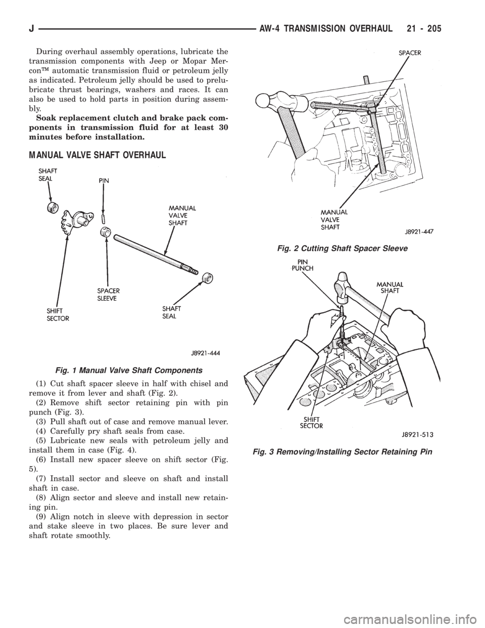
(1) Cut shaft spacer sleeve in half with chisel and
remove it from lever and shaft (Fig. 2).
(2) Remove shift sector retaining pin with pin
punch (Fig. 3).
(3) Pull shaft out of case and remove manual lever.
(4) Carefully pry shaft seals from case.
(5) Lubricate new seals with petroleum jelly and
install them in case (Fig. 4).
(6) Install new spacer sleeve on shift sector (Fig.
5).
(7) Install sector and sleeve on shaft and install
shaft in case.
(8) Align sector and sleeve and install new retain-
ing pin.
(9) Align notch in sleeve with depression in sector
and stake sleeve in two places. Be sure lever and
shaft rotate smoothly.
Fig. 1 Manual Valve Shaft Components
Fig. 2 Cutting Shaft Spacer Sleeve
Fig. 3 Removing/Installing Sector Retaining Pin
JAW-4 TRANSMISSION OVERHAUL 21 - 205
Page 1361 of 1784
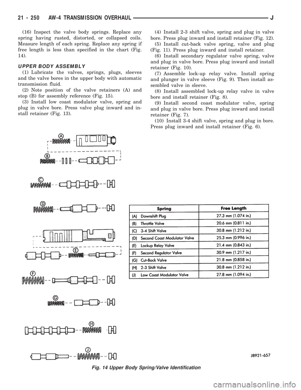
(16) Inspect the valve body springs. Replace any
spring having rusted, distorted, or collapsed coils.
Measure length of each spring. Replace any spring if
free length is less than specified in the chart (Fig.
14).
UPPER BODY ASSEMBLY
(1) Lubricate the valves, springs, plugs, sleeves
and the valve bores in the upper body with automatic
transmission fluid.
(2) Note position of the valve retainers (A) and
stop (B) for assembly reference (Fig. 15).
(3) Install low coast modulator valve, spring and
plug in valve bore. Press valve plug inward and in-
stall retainer (Fig. 13).(4) Install 2-3 shift valve, spring and plug in valve
bore. Press plug inward and install retainer (Fig. 12).
(5) Install cut-back valve spring, valve and plug
(Fig. 11). Press plug inward and install retainer.
(6) Install secondary regulator valve spring, valve
and plug in valve bore. Press plug inward and install
retainer (Fig. 10).
(7) Assemble lock-up relay valve. Install spring
and plunger in valve sleeve (Fig. 9). Then install as-
sembled valve in sleeve.
(8) Install assembled lock-up relay valve in valve
bore and install retainer (Fig. 8).
(9) Install second coast modulator valve, spring
and plug in valve bore. Press plug inward and install
retainer (Fig. 7).
(10) Install 3-4 shift valve, spring and plug in bore.
Press plug inward and install retainer (Fig. 6).
Fig. 14 Upper Body Spring/Valve Identification
21 - 250 AW-4 TRANSMISSION OVERHAULJ
Page 1387 of 1784
TRANSFER CASE REMOVAL
(1) Shift transfer case into Neutral.
(2) Raise vehicle.
(3) Drain transfer case lubricant.
(4) Mark front and rear propeller shaft yokes for
alignment reference.
(5) Support transmission with jack stand.
(6) Remove rear crossmember, or skid plate.
(7) Disconnect front/rear propeller shafts at trans-
fer case.
(8) Disconnect vehicle speed sensor wires.(9) Disconnect transfer case linkage rod from range
lever.
(10) Disconnect transfer case vent hose.
(11) Support transfer case with transmission jack.
(12) Remove nuts attaching transfer case to trans-
mission.
(13) Secure transfer case to jack with chains.
(14) Pull transfer case and jack rearward to disen-
gage transfer case.
(15) Remove transfer case from under vehicle.
TRANSFER CASE INSTALLATION
(1) Mount transfer case on a transmission jack. Se-
cure transfer case to jack with chains.
(2) Position transfer case under vehicle.
(3) Align transfer case and transmission shafts and
install transfer case on transmission.
(4) Install and tighten transfer case attaching nuts
to 35 Nzm (26 ft. lbs.) torque.
(5) Connect vehicle speed sensor wires, and vent hose.
(6) Align and connect propeller shafts. Tighten
shaft attaching bolts to 19 Nzm (170 in. lbs.) torque.
(7) Fill transfer case with Mopar ATF Plus, or
Dexron II automatic transmission fluid.
(8) Install rear crossmember, or skid plate. Tighten
crossmember bolts to 41 Nzm (30 ft. lbs.) torque.
(9) Remove transmission jack and transmission
support stand.
(10) Connect transfer case range lever to linkage rod.
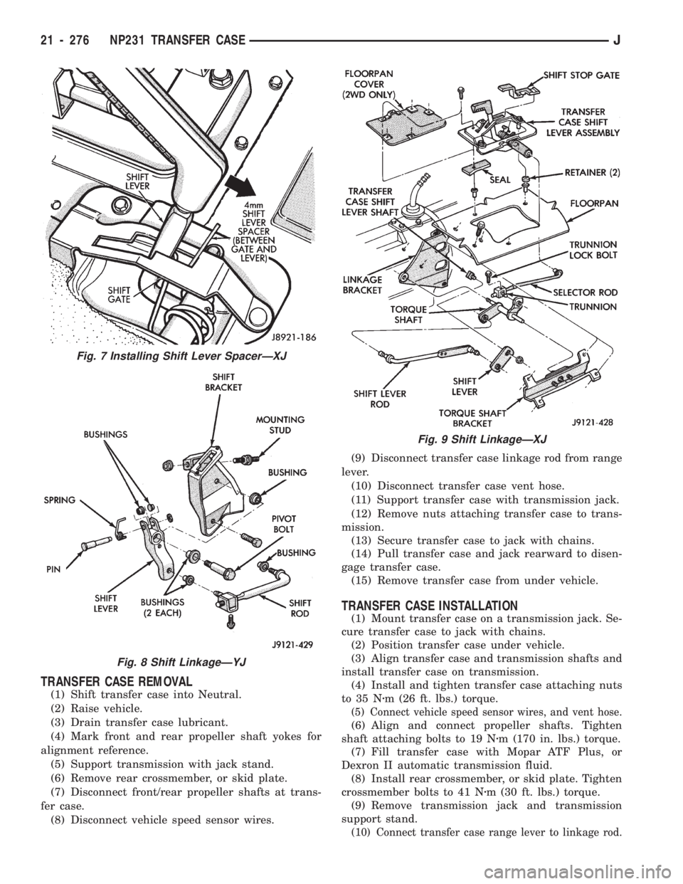
Fig. 7 Installing Shift Lever SpacerÐXJ
Fig. 8 Shift LinkageÐYJ
Fig. 9 Shift LinkageÐXJ
21 - 276 NP231 TRANSFER CASEJ
Page 1397 of 1784
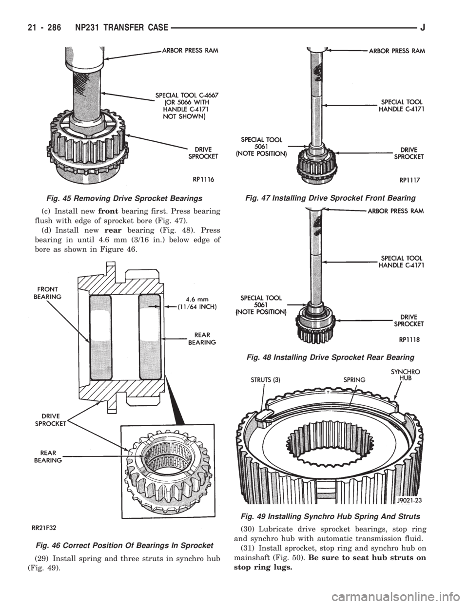
(c) Install newfrontbearing first. Press bearing
flush with edge of sprocket bore (Fig. 47).
(d) Install newrearbearing (Fig. 48). Press
bearing in until 4.6 mm (3/16 in.) below edge of
bore as shown in Figure 46.
(29) Install spring and three struts in synchro hub
(Fig. 49).(30) Lubricate drive sprocket bearings, stop ring
and synchro hub with automatic transmission fluid.
(31) Install sprocket, stop ring and synchro hub on
mainshaft (Fig. 50).Be sure to seat hub struts on
stop ring lugs.
Fig. 45 Removing Drive Sprocket Bearings
Fig. 46 Correct Position Of Bearings In Sprocket
Fig. 47 Installing Drive Sprocket Front Bearing
Fig. 48 Installing Drive Sprocket Rear Bearing
Fig. 49 Installing Synchro Hub Spring And Struts
21 - 286 NP231 TRANSFER CASEJ