1994 JEEP CHEROKEE automatic transmission fluid
[x] Cancel search: automatic transmission fluidPage 1401 of 1784
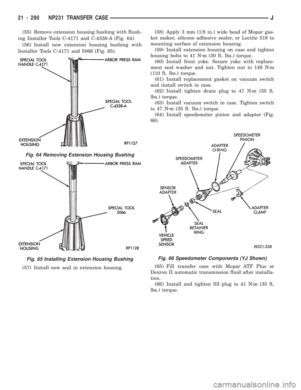
(55) Remove extension housing bushing with Bush-
ing Installer Tools C-4171 and C-4338-A (Fig. 64).
(56) Install new extension housing bushing with
Installer Tools C-4171 and 5066 (Fig. 65).
(57) Install new seal in extension housing.(58) Apply 3 mm (1/8 in.) wide bead of Mopar gas-
ket maker, silicone adhesive sealer, or Loctite 518 to
mounting surface of extension housing.
(59) Install extension housing on case and tighten
housing bolts to 41 Nzm (30 ft. lbs.) torque.
(60) Install front yoke. Secure yoke with replace-
ment seal washer and nut. Tighten nut to 149 Nzm
(110 ft. lbs.) torque.
(61) Install replacement gasket on vacuum switch
and install switch in case.
(62) Install tighten drain plug to 47 Nzm (35 ft.
lbs.) torque.
(63) Install vacuum switch in case. Tighten switch
to 47 Nzm (35 ft. lbs.) torque.
(64) Install speedometer pinion and adapter (Fig.
66).
(65) Fill transfer case with Mopar ATF Plus or
Dexron II automatic transmission fluid after installa-
tion.
(66) Install and tighten fill plug to 41 Nzm (35 ft.
lbs.) torque.
Fig. 64 Removing Extension Housing Bushing
Fig. 65 Installing Extension Housing BushingFig. 66 Speedometer Components (YJ Shown)
21 - 290 NP231 TRANSFER CASEJ
Page 1405 of 1784
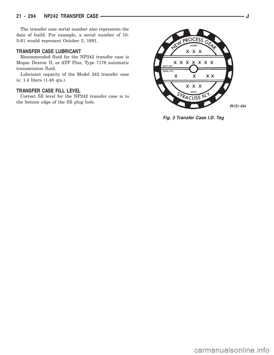
The transfer case serial number also represents the
date of build. For example, a serial number of 10-
5-91 would represent October 5, 1991.
TRANSFER CASE LUBRICANT
Recommended fluid for the NP242 transfer case is
Mopar Dexron II, or ATF Plus, Type 7176 automatic
transmission fluid.
Lubricant capacity of the Model 242 transfer case
is: 1.4 liters (1.48 qts.).
TRANSFER CASE FILL LEVEL
Correct fill level for the NP242 transfer case is to
the bottom edge of the fill plug hole.
Fig. 3 Transfer Case I.D. Tag
21 - 294 NP242 TRANSFER CASEJ
Page 1407 of 1784
SHIFT LINKAGE ADJUSTMENT
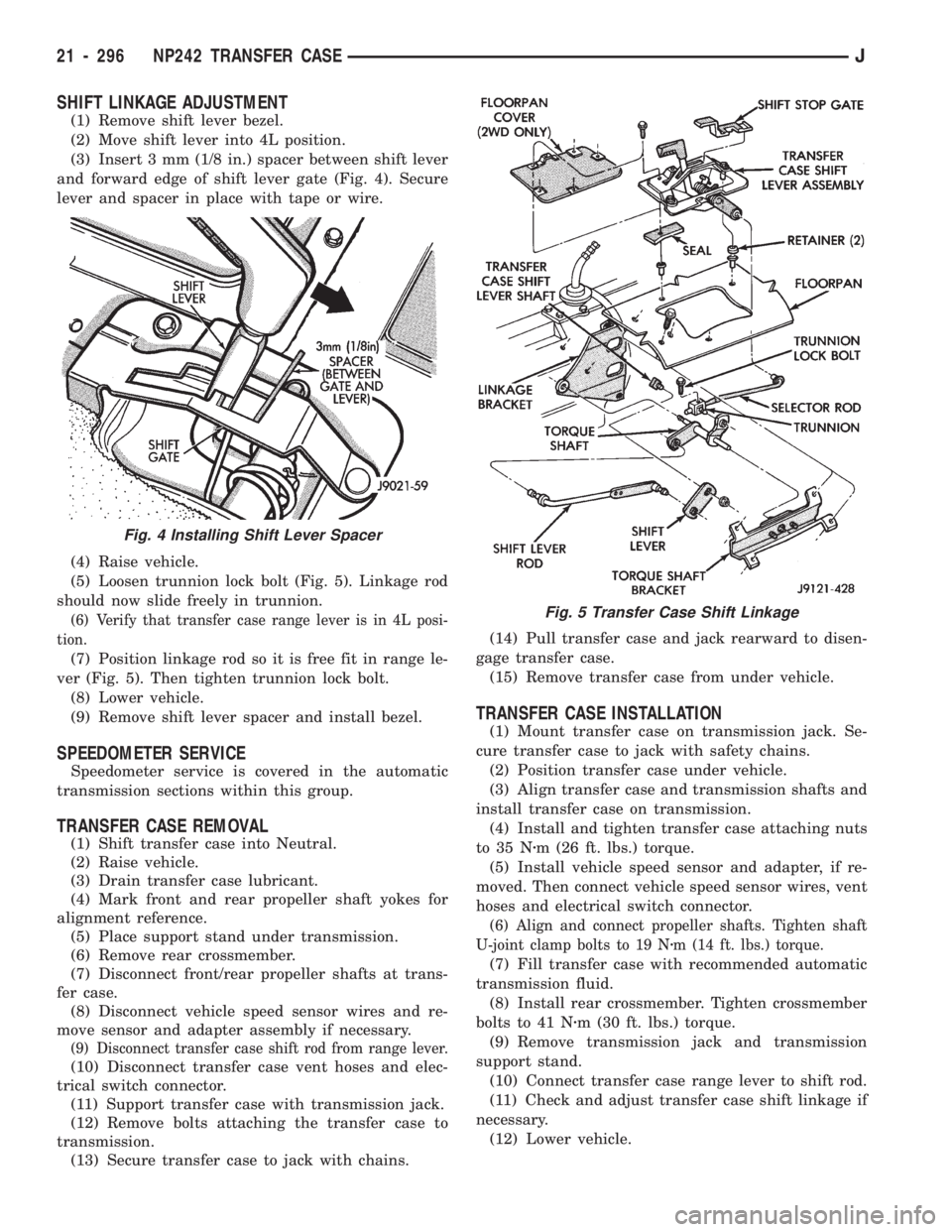
(1) Remove shift lever bezel.
(2) Move shift lever into 4L position.
(3) Insert 3 mm (1/8 in.) spacer between shift lever
and forward edge of shift lever gate (Fig. 4). Secure
lever and spacer in place with tape or wire.
(4) Raise vehicle.
(5) Loosen trunnion lock bolt (Fig. 5). Linkage rod
should now slide freely in trunnion.
(6) Verify that transfer case range lever is in 4L posi-
tion.
(7) Position linkage rod so it is free fit in range le-
ver (Fig. 5). Then tighten trunnion lock bolt.
(8) Lower vehicle.
(9) Remove shift lever spacer and install bezel.
SPEEDOMETER SERVICE
Speedometer service is covered in the automatic
transmission sections within this group.
TRANSFER CASE REMOVAL
(1) Shift transfer case into Neutral.
(2) Raise vehicle.
(3) Drain transfer case lubricant.
(4) Mark front and rear propeller shaft yokes for
alignment reference.
(5) Place support stand under transmission.
(6) Remove rear crossmember.
(7) Disconnect front/rear propeller shafts at trans-
fer case.
(8) Disconnect vehicle speed sensor wires and re-
move sensor and adapter assembly if necessary.
(9) Disconnect transfer case shift rod from range lever.
(10) Disconnect transfer case vent hoses and elec-
trical switch connector.
(11) Support transfer case with transmission jack.
(12) Remove bolts attaching the transfer case to
transmission.
(13) Secure transfer case to jack with chains.(14) Pull transfer case and jack rearward to disen-
gage transfer case.
(15) Remove transfer case from under vehicle.
TRANSFER CASE INSTALLATION
(1) Mount transfer case on transmission jack. Se-
cure transfer case to jack with safety chains.
(2) Position transfer case under vehicle.
(3) Align transfer case and transmission shafts and
install transfer case on transmission.
(4) Install and tighten transfer case attaching nuts
to 35 Nzm (26 ft. lbs.) torque.
(5) Install vehicle speed sensor and adapter, if re-
moved. Then connect vehicle speed sensor wires, vent
hoses and electrical switch connector.
(6) Align and connect propeller shafts. Tighten shaft
U-joint clamp bolts to 19 Nzm (14 ft. lbs.) torque.
(7) Fill transfer case with recommended automatic
transmission fluid.
(8) Install rear crossmember. Tighten crossmember
bolts to 41 Nzm (30 ft. lbs.) torque.
(9) Remove transmission jack and transmission
support stand.
(10) Connect transfer case range lever to shift rod.
(11) Check and adjust transfer case shift linkage if
necessary.
(12) Lower vehicle.
Fig. 4 Installing Shift Lever Spacer
Fig. 5 Transfer Case Shift Linkage
21 - 296 NP242 TRANSFER CASEJ
Page 1417 of 1784
Inspect the differential gears, thrust washers and
case halves. Replace the mainshaft gear if the gear
teeth or the brass ring on the underside of the gear
are damaged. Replace the differential as an assembly
if the gears, case halves, or the pins in the lower case
half are damaged.
Inspect the case halves, extension housing and re-
tainers for cracks, porosity, or damaged sealing sur-
faces. Inspect the shafts, gears, chain and shift
components for wear or damage.
Inspect all of the transfer case bearings for wear,
roughness, pitting, or galling. Replace worn or dam-
aged bearings as outlined in the assembly section.
TRANSFER CASE ASSEMBLY
(1) Lubricate the transfer case components with
automatic transmission fluid or petroleum jelly
(where indicated) during assembly.
CAUTION: The bearing bores in various transfer
case components contain oil feed holes. Be sure re-
placement bearings do not block these feed holes.
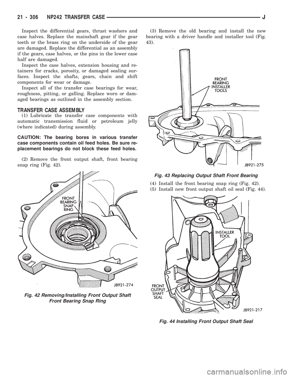
(2) Remove the front output shaft, front bearing
snap ring (Fig. 42).(3) Remove the old bearing and install the new
bearing with a driver handle and installer tool (Fig.
43).
(4) Install the front bearing snap ring (Fig. 42).
(5) Install new front output shaft oil seal (Fig. 44).
Fig. 42 Removing/Installing Front Output Shaft
Front Bearing Snap Ring
Fig. 43 Replacing Output Shaft Front Bearing
Fig. 44 Installing Front Output Shaft Seal
21 - 306 NP242 TRANSFER CASEJ
Page 1419 of 1784
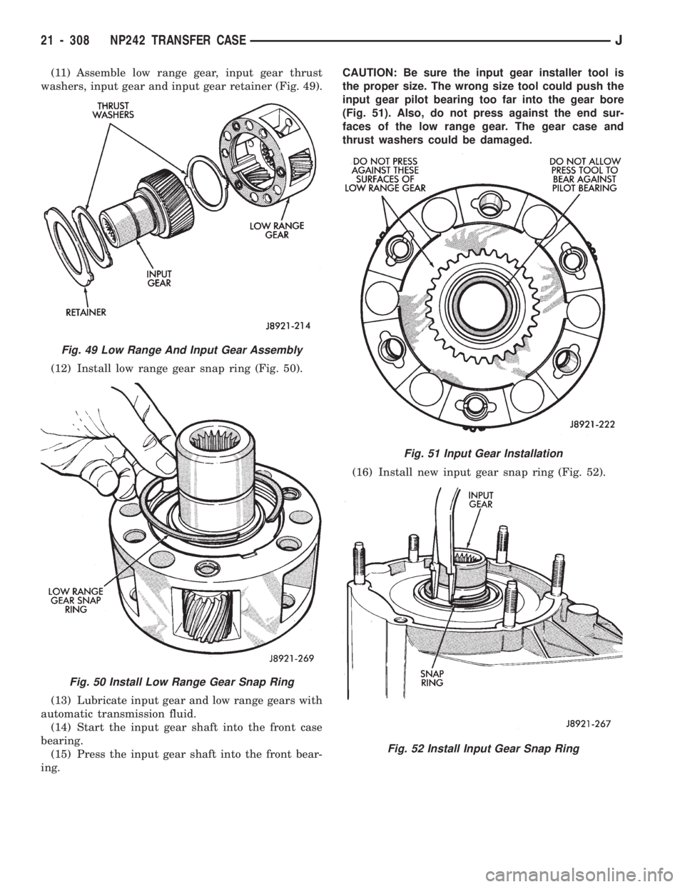
(11) Assemble low range gear, input gear thrust
washers, input gear and input gear retainer (Fig. 49).
(12) Install low range gear snap ring (Fig. 50).
(13) Lubricate input gear and low range gears with
automatic transmission fluid.
(14) Start the input gear shaft into the front case
bearing.
(15) Press the input gear shaft into the front bear-
ing.CAUTION: Be sure the input gear installer tool is
the proper size. The wrong size tool could push the
input gear pilot bearing too far into the gear bore
(Fig. 51). Also, do not press against the end sur-
faces of the low range gear. The gear case and
thrust washers could be damaged.
(16) Install new input gear snap ring (Fig. 52).
Fig. 49 Low Range And Input Gear Assembly
Fig. 50 Install Low Range Gear Snap Ring
Fig. 51 Input Gear Installation
Fig. 52 Install Input Gear Snap Ring
21 - 308 NP242 TRANSFER CASEJ
Page 1543 of 1784
The reinforcement bracket is held on the
frame rail with two blind rivets.
(2) Remove the bracket and tow hook from frame
rail.
INSTALLATION
(1) Position bracket and tow hook on the frame
rail.
(2) Install bolts that attach tow hook bracket to
frame rail and reinforcement bracket. Tighten bolts
to 75 Nzm (55 ft-lbs) torque.
TRAILER HITCHES
CLASS III HITCHÐXJ VEHICLES
A class III weight-distributing/equalizer type hitch
can be used to tow a trailer:
²having a maximum gross weight of 5,000 lbs/2250
kg, and
²having a maximum tongue weight of 750 lbs/332
kg).
The following vehicle basic equipment is required
for class III trailer towing:
²P205/75R15 or larger tires;
²full size spare tire;
²trailer sway control;
²trailer tow wire harness and connector;
²heavy duty turn signal flasher element;
²heavy duty axle (with synthetic lubricant);²heavy duty cooling system;
²heavy duty generator/battery;
²auxiliary automatic transmission fluid cooler; and
²I-6, 4.0L engine.
Wide-angle type door mirrors are recommended but
not required.
WIRE HARNESS CONNECTORS
CLASS I HITCH CONNECTOR
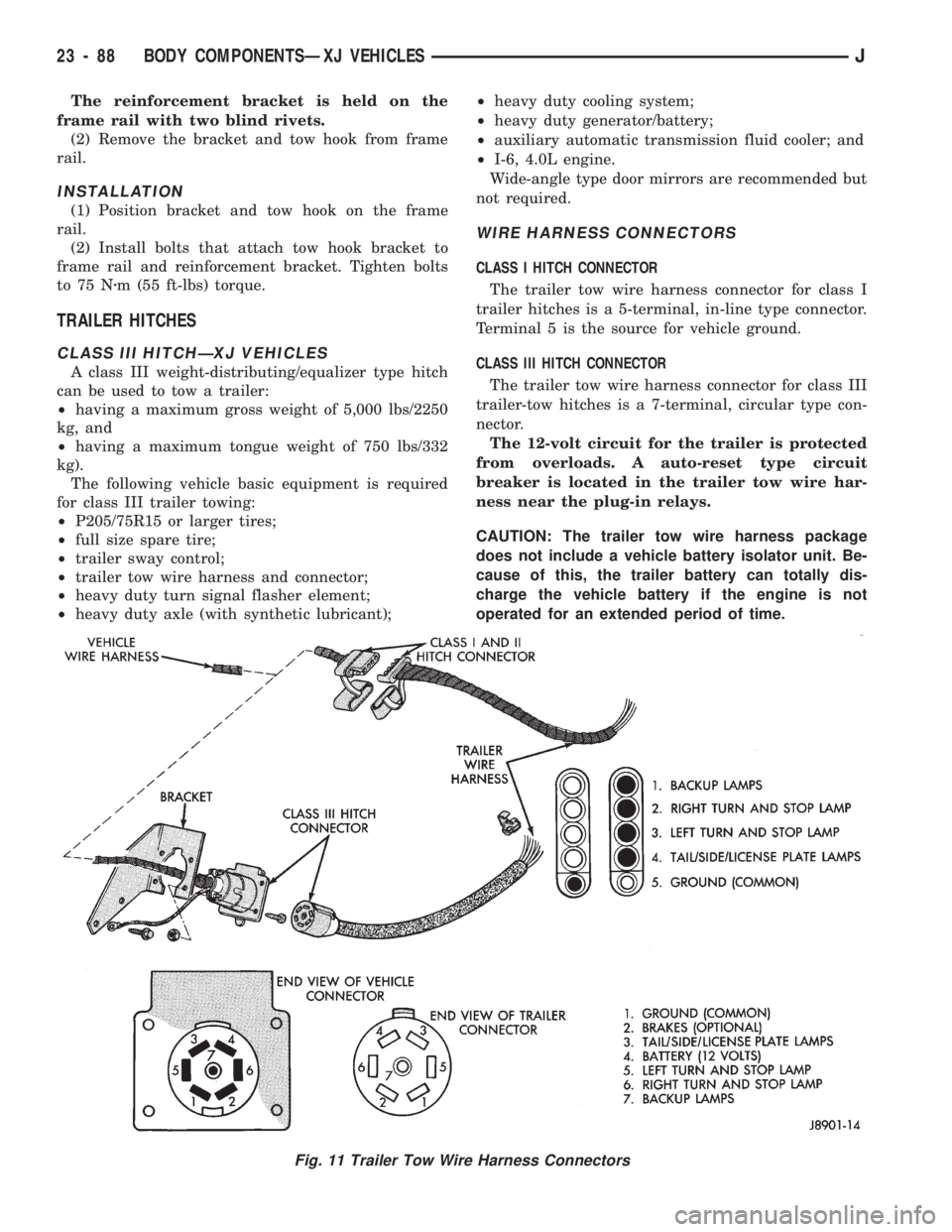
The trailer tow wire harness connector for class I
trailer hitches is a 5-terminal, in-line type connector.
Terminal 5 is the source for vehicle ground.
CLASS III HITCH CONNECTOR
The trailer tow wire harness connector for class III
trailer-tow hitches is a 7-terminal, circular type con-
nector.
The 12-volt circuit for the trailer is protected
from overloads. A auto-reset type circuit
breaker is located in the trailer tow wire har-
ness near the plug-in relays.
CAUTION: The trailer tow wire harness package
does not include a vehicle battery isolator unit. Be-
cause of this, the trailer battery can totally dis-
charge the vehicle battery if the engine is not
operated for an extended period of time.
Fig. 11 Trailer Tow Wire Harness Connectors
23 - 88 BODY COMPONENTSÐXJ VEHICLESJ
Page 1695 of 1784
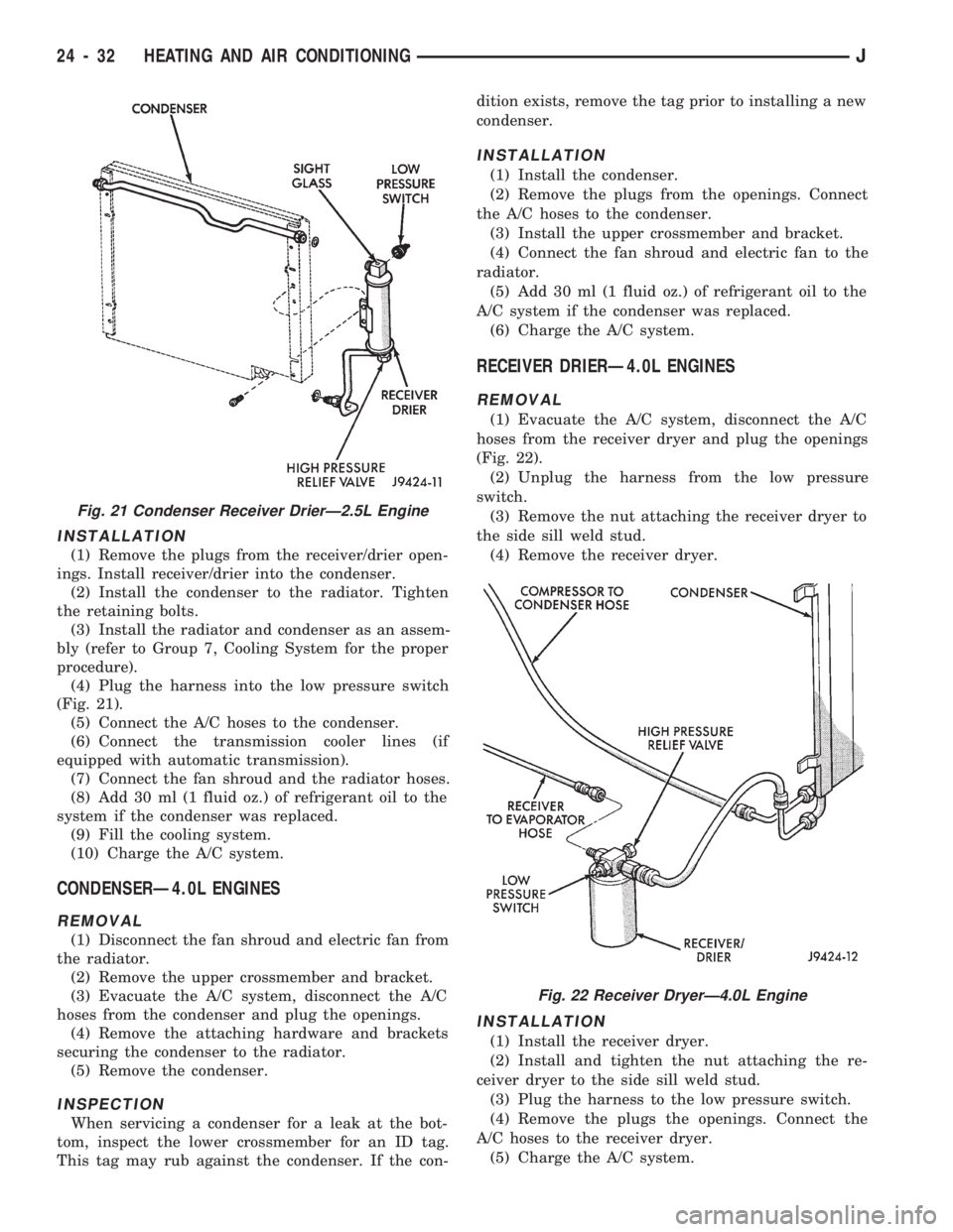
INSTALLATION
(1) Remove the plugs from the receiver/drier open-
ings. Install receiver/drier into the condenser.
(2) Install the condenser to the radiator. Tighten
the retaining bolts.
(3) Install the radiator and condenser as an assem-
bly (refer to Group 7, Cooling System for the proper
procedure).
(4) Plug the harness into the low pressure switch
(Fig. 21).
(5) Connect the A/C hoses to the condenser.
(6) Connect the transmission cooler lines (if
equipped with automatic transmission).
(7) Connect the fan shroud and the radiator hoses.
(8) Add 30 ml (1 fluid oz.) of refrigerant oil to the
system if the condenser was replaced.
(9) Fill the cooling system.
(10) Charge the A/C system.
CONDENSERÐ4.0L ENGINES
REMOVAL
(1) Disconnect the fan shroud and electric fan from
the radiator.
(2) Remove the upper crossmember and bracket.
(3) Evacuate the A/C system, disconnect the A/C
hoses from the condenser and plug the openings.
(4) Remove the attaching hardware and brackets
securing the condenser to the radiator.
(5) Remove the condenser.
INSPECTION
When servicing a condenser for a leak at the bot-
tom, inspect the lower crossmember for an ID tag.
This tag may rub against the condenser. If the con-dition exists, remove the tag prior to installing a new
condenser.
INSTALLATION
(1) Install the condenser.
(2) Remove the plugs from the openings. Connect
the A/C hoses to the condenser.
(3) Install the upper crossmember and bracket.
(4) Connect the fan shroud and electric fan to the
radiator.
(5) Add 30 ml (1 fluid oz.) of refrigerant oil to the
A/C system if the condenser was replaced.
(6) Charge the A/C system.
RECEIVER DRIERÐ4.0L ENGINES
REMOVAL
(1) Evacuate the A/C system, disconnect the A/C
hoses from the receiver dryer and plug the openings
(Fig. 22).
(2) Unplug the harness from the low pressure
switch.
(3) Remove the nut attaching the receiver dryer to
the side sill weld stud.
(4) Remove the receiver dryer.
INSTALLATION
(1) Install the receiver dryer.
(2) Install and tighten the nut attaching the re-
ceiver dryer to the side sill weld stud.
(3) Plug the harness to the low pressure switch.
(4) Remove the plugs the openings. Connect the
A/C hoses to the receiver dryer.
(5) Charge the A/C system.
Fig. 21 Condenser Receiver DrierÐ2.5L Engine
Fig. 22 Receiver DryerÐ4.0L Engine
24 - 32 HEATING AND AIR CONDITIONINGJ
Page 1698 of 1784
(5) Install the evaporator/blower housing.
(6) Add 30 ml (1 fluid oz.) of refrigerant oil to the
air conditioning system if the evaporator was re-
placed.
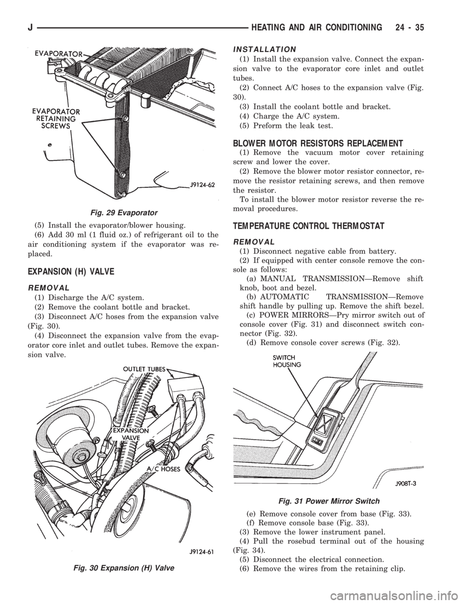
EXPANSION (H) VALVE
REMOVAL
(1) Discharge the A/C system.
(2) Remove the coolant bottle and bracket.
(3) Disconnect A/C hoses from the expansion valve
(Fig. 30).
(4) Disconnect the expansion valve from the evap-
orator core inlet and outlet tubes. Remove the expan-
sion valve.
INSTALLATION
(1) Install the expansion valve. Connect the expan-
sion valve to the evaporator core inlet and outlet
tubes.
(2) Connect A/C hoses to the expansion valve (Fig.
30).
(3) Install the coolant bottle and bracket.
(4) Charge the A/C system.
(5) Preform the leak test.
BLOWER MOTOR RESISTORS REPLACEMENT
(1) Remove the vacuum motor cover retaining
screw and lower the cover.
(2) Remove the blower motor resistor connector, re-
move the resistor retaining screws, and then remove
the resistor.
To install the blower motor resistor reverse the re-
moval procedures.
TEMPERATURE CONTROL THERMOSTAT
REMOVAL
(1) Disconnect negative cable from battery.
(2) If equipped with center console remove the con-
sole as follows:
(a) MANUAL TRANSMISSIONÐRemove shift
knob, boot and bezel.
(b) AUTOMATIC TRANSMISSIONÐRemove
shift handle by pulling up. Remove the shift bezel.
(c) POWER MIRRORSÐPry mirror switch out of
console cover (Fig. 31) and disconnect switch con-
nector (Fig. 32).
(d) Remove console cover screws (Fig. 32).
(e) Remove console cover from base (Fig. 33).
(f) Remove console base (Fig. 33).
(3) Remove the lower instrument panel.
(4) Pull the rosebud terminal out of the housing
(Fig. 34).
(5) Disconnect the electrical connection.
(6) Remove the wires from the retaining clip.
Fig. 29 Evaporator
Fig. 30 Expansion (H) Valve
Fig. 31 Power Mirror Switch
JHEATING AND AIR CONDITIONING 24 - 35