1994 JEEP CHEROKEE maintenance schedule
[x] Cancel search: maintenance schedulePage 2 of 1784
LUBRICATION AND MAINTENANCE
CONTENTS
page page
CHASSIS AND BODY COMPONENTS....... 30
DRIVETRAIN........................... 22
ENGINE MAINTENANCE.................. 13GENERAL INFORMATION.................. 1
JUMP STARTING, HOISTING AND TOWING . . 7
MAINTENANCE SCHEDULES............... 5
GENERAL INFORMATION
INDEX
page page
Classification of Lubricants.................. 2
Components Requiring No Lubrication.......... 3
Fluid Capacities.......................... 4
Fuel Requirements........................ 2Introduction.............................. 1
Recommended Lubricant and Replacement Parts . 3
Routine Service........................... 2
INTRODUCTION
Jeeptlubrication and maintenance is divided into
required and recommended service tasks.
The recommendations and procedures listed in this
group are intended for JeeptDealer Service Personnel.
Because conditions vary, it is necessary to schedule
service tasks according to a time interval as well as a
distance interval.
It is the owner's responsibility to have vehicle ser-
viced. Owner is to pay for labor and necessary parts
that are not covered by the warranty.
Additional lubrication and maintenance informa-
tion is listed in the Owner's Manual, which is in-
cluded with the vehicle.
SEVERE DRIVING CONDITIONS
When a vehicle is subjected to a severe driving con-
dition, time between recommended maintenance
should be decreased.
Refer to Engine Maintenance for the engine oil and
filter maintenance interval when involved with a se-
vere driving condition.
A severe driving condition is defined as either:
²frequent short trip driving less than 24 km (15
miles);
²frequent driving in a dusty environment;
²trailer towing;
²extensive engine idling;
²sustained high-speed operation;
²desert operation;
²frequent starting and stopping;²cold-climate operation;
²off-road driving; or
²commercial service.
To service a Jeeptvehicle for a severe driving con-
dition, change all the lubricating fluids and lubricate:
²the body components,
²all the driveline coupling joints, and
²the steering linkage
more often than for a normal driving condition to
prevent excessive wear of the components.
DUSTY AREAS
Driving in an area with dust-filled air increases the
risk of particles entering the engine and crankcase.
With this type of severe driving condition, attention
should be given to the engine and crankcase compo-
nents.
OFF-ROAD (4WD) OPERATION
After completion of off-road (4WD) operation, the
underside of the vehicle should be thoroughly in-
spected. Examine threaded fasteners for looseness.
HARSH SURFACE ENVIRONMENTS
After vehicle operation in a harsh surface environ-
ment, the following components should be inspected
and cleaned as soon as possible:
²brake drums,
²brake linings,
²front wheel bearings (2WD vehicles only), and
²axle coupling joints.
This will prevent wear and/or unpredictable brake
action.
JLUBRICATION AND MAINTENANCE 0 - 1
Page 6 of 1784

MAINTENANCE SCHEDULES
INTRODUCTION
Chrysler Corporation has compiled recommended
lubrication and maintenance schedules and proce-
dures to help reduce premature wear or failure over
a broad range of operating conditions.
SEVERE SERVICE MAINTENANCE
If the vehicle is involved with a severe driving con-
dition, after each 4 800-km (3,000-miles)/3-month in-
terval. A severe driving condition includes:
²frequent short trip driving less than 24 km (15
miles);
²frequent driving in a dusty environment;
²trailer towing;
²extensive engine idling;
²sustained high-speed operation;
²desert operation;
²frequent starting and stopping;
²cold-climate operation;
²off-road driving; or
²commercial service.
MAINTENANCE SCHEDULES
AT EACH STOP FOR FUEL
²Check engine oil level, add as required.
²
Check windshield washer solvent and add if required.
ONCE A MONTH
²Check tire pressure and look for unusual wear or
damage.
²Inspect battery and clean and tighten terminals as
required.
²Check electrolyte level and add water as needed.
²Check fluid levels of coolant reservoir, power steer-
ing and transmission and add as needed.
²Check all lights and all other electrical items for
correct operation.
²Check rubber seals on each side of the radiator for
proper fit.
7,500 MILES (12 000 KM) OR AT 6 MONTHS
²Check engine coolant level, hoses and clamps.
²Change engine oil.
²Replace engine oil filter.
²Check exhaust system.
²Lubricate steering linkage (4x4 models).
²Lubricate propeller shaft universal joints.
²Rotate Tires.
15,000 MILES (24 000 KM) OR AT 12 MONTHS
²Check engine coolant level, hoses and clamps.
²Change engine oil.
²Replace engine oil filter.
²Check exhaust system.
²Lubricate steering linkage (4x4 models).
²Lubricate propeller shaft universal joints.²Check fluid level in battery.
²Rotate Tires.
22,500 MILES (36 000 KM) OR AT 18 MONTHS
²Check engine coolant level, hoses and clamps.
²Change engine oil.
²Replace engine oil filter.
²Check exhaust system.
²Lubricate steering linkage (4x4 models).
²Lubricate propeller shaft universal joints.
²Rotate Tires.
30,000 MILES (48 000 KM) OR AT 24 MONTHS
²Replace air cleaner filter.
²Replace spark plugs.
²Adjust drive belt.
²Check engine coolant level, hoses and clamps.
²Change engine oil.
²Replace engine oil filter.
²Check exhaust system.
²Lubricate steering linkage (4x4 models).
²Lubricate propeller shaft universal joints.
²Check fluid level in battery.
²Drain and refill automatic transmission.
²Drain and refill transfer case.
²Rotate Tires.
37,500 MILES (60 000 KM) OR AT 30 MONTHS
²Check engine coolant level, hoses and clamps.
²Change engine oil.
²Replace engine oil filter.
²Check exhaust system.
²Lubricate steering linkage (4x4 models).
²Lubricate propeller shaft universal joints.
²Drain and refill manual transmission.
²Rotate Tires.
45,000 MILES (72 500 KM) OR AT 36 MONTHS
²Check engine coolant level, hoses and clamps.
²Change engine oil.
²Replace engine oil filter.
²Check exhaust system.
²Lubricate steering linkage (4x4 models).
²Lubricate propeller shaft universal joints.
²Check fluid level in battery.
²Rotate Tires.
52,500 MILES (84 500 KM) OR AT 42 MONTHS
²Flush and replace engine coolant.
²Check engine coolant system hoses and clamps.
²Change engine oil.
²Replace engine oil filter.
²Check exhaust system.
²Lubricate steering linkage (4x4 models).
²Lubricate propeller shaft universal joints.
²Rotate Tires.
JLUBRICATION AND MAINTENANCE 0 - 5
Page 14 of 1784

ENGINE MAINTENANCE
INDEX
page page
Accessory Drive Belt...................... 20
Air-Conditioner Compressor/Hoses/Fittings...... 21
Battery................................ 18
Cooling System.......................... 16
Crankcase Ventilation System............... 17
Engine Air Cleaner Filter Element............ 16
Engine Break-In......................... 13
Engine Oil.............................. 13Engine Oil Change and Filter Replacement..... 15
Engine Oil Filter......................... 14
Engine Supports......................... 20
Exhaust System......................... 20
Fuel Usage StatementÐGas Engines......... 17
Ignition Cables, Distributor Cap and Rotor...... 18
Rubber and Plastic Ducts/Hoses/Tubing....... 19
Spark Plugs............................ 18
ENGINE BREAK-IN
After first starting a new engine, allow it to idle
and warm up for at least 15 seconds before shifting
the transmission into a drive gear.
Drive the vehicle at:
²varying speeds less than 80 km/h (50 mph) for the
first 160 km (100 miles), and
²speeds less than 88 km/h (55 mph) for the first 800
km (500 miles).
Avoid driving at full-throttle for extended periods
of time. Also, avoid fast acceleration and sudden
stops.
A special break-in engine oil is not required. The
original oil installed in a vehicle is a quality lubri-
cant. There is no requirement to have the oil
changed or the oil filter replaced until the first
scheduled maintenance interval.
The engine oil, coolant and all the other engine re-
lated fluid levels should be determined on a regular
basis.
ENGINE OIL
SPECIFICATIONS
API SERVICE GRADE
For maximum engine protection during all driving
conditions, install an engine oil that conforms to API
Service Grade. MOPAR Engine Oil conforms to all of
these API Service Grades.
SAE VISCOSITY
SAE designated multi-viscosity grade engine oil is
to protect engines. This type of engine oil can usually
be installed and remain in the engine until the next
scheduled oil change. Select the engine oil viscosity
according to the lowest ambient air temperature ex-
pected before the next scheduled oil change (Fig.1).
Low viscosity engine oil allows easier engine starting
during cold weather. SAE 5W-30 viscosity engine oil
is recommended when the ambient air temperatures
consistently decrease to below 10ÉF (-12ÉC).ENERGY CONSERVING OIL
In selecting the correct API grade and SAE grade,
anENERGY CONSERVINGtype engine oil is also
recommended.
CONTAINER IDENTIFICATION
Standard engine oil notations have been adopted
for selection of engine oil. The notations are located
on side of plastic bottles and on the top of engine oil
cans (Fig. 2).
²The top, outer field contains theAPI Service
Gradenotation for the engine oil.
Fig. 1 Temperature/Engine Oil Viscosity
Fig. 2 Engine Oil Container Standard Notations
JLUBRICATION AND MAINTENANCE 0 - 13
Page 93 of 1784
pressure is bleeding past the (in-tank mounted) fuel
pump outlet check valve. Replace Fuel Pump Module
assembly. Refer to Fuel Pump Module removal and
installation in this group. If pressure drop is within
specifications, proceed to next step.
(13) Clamp off the rubber hose portion of adapter
tool number 6631 connected to the fuel supply line.
Allow engine to set for 30 minutes. If pressure has
dropped more than 138 kPa (20 psi) in 30 minutes,
pressure is bleeding past the fuel pressure regulator.
Replace fuel pressure regulator. Refer to Fuel Rail
removal and installation in the Component Removal/
Installation section of this group.
MECHANICAL MALFUNCTIONS
Mechanical malfunctions are more difficult to diag-
nose with this system. The powertrain control mod-
ule (PCM) has been programmed to compensate for
some mechanical malfunctions such as incorrect cam
timing, vacuum leaks, etc. If engine performance
problems are encountered and diagnostic trouble
codes are not displayed, the problem may be mechan-
ical rather than electronic.
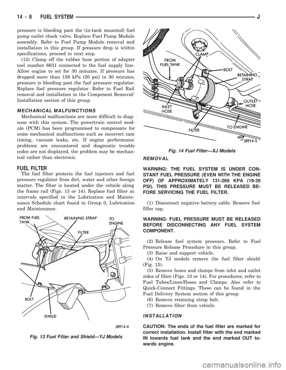
FUEL FILTER
The fuel filter protects the fuel injectors and fuel
pressure regulator from dirt, water and other foreign
matter. The filter is located under the vehicle along
the frame rail (Figs. 13 or 14). Replace fuel filter at
intervals specified in the Lubrication and Mainte-
nance Schedule chart found in Group 0, Lubrication
and Maintenance.
REMOVAL
WARNING: THE FUEL SYSTEM IS UNDER CON-
STANT FUEL PRESSURE (EVEN WITH THE ENGINE
OFF) OF APPROXIMATELY 131-269 KPA (19-39
PSI). THIS PRESSURE MUST BE RELEASED BE-
FORE SERVICING THE FUEL FILTER.
(1) Disconnect negative battery cable. Remove fuel
filler cap.
WARNING: FUEL PRESSURE MUST BE RELEASED
BEFORE DISCONNECTING ANY FUEL SYSTEM
COMPONENT.
(2) Release fuel system pressure. Refer to Fuel
Pressure Release Procedure in this group.
(3) Raise and support vehicle.
(4) On YJ models remove the fuel filter shield
(Fig. 13).
(5) Remove hoses and clamps from inlet and outlet
sides of filter (Figs. 13 or 14). For procedures, refer to
Fuel Tubes/Lines/Hoses and Clamps. Also refer to
Quick-Connect Fittings. These can be found in the
Fuel Delivery System section of this group.
(6) Remove retaining strap bolt.
(7) Remove filter from vehicle.
INSTALLATION
CAUTION: The ends of the fuel filter are marked for
correct installation. Install filter with the end marked
IN towards fuel tank and the end marked OUT to-
wards engine.
Fig. 13 Fuel Filter and ShieldÐYJ Models
Fig. 14 Fuel FilterÐXJ Models
14 - 8 FUEL SYSTEMJ
Page 314 of 1784

IGNITION SYSTEMS
CONTENTS
page page
COMPONENT IDENTIFICATION/SYSTEM
OPERATION.......................... 1
COMPONENT REMOVAL/INSTALLATION..... 20DIAGNOSTICS/SERVICE PROCEDURES....... 8
IGNITION SWITCH...................... 30
SPECIFICATIONS....................... 33
COMPONENT IDENTIFICATION/SYSTEM OPERATION
INDEX
page page
Automatic Shut Down (ASD) Relay............ 1
Camshaft Position Sensor................... 1
Crankshaft Position Sensor.................. 2
Distributors.............................. 3
Engine Coolant Temperature Sensor........... 4
General Information........................ 1Ignition Coil.............................. 4
Intake Manifold Air Temperature Sensor........ 5
Manifold Absolute Pressure (MAP) Sensor...... 5
Powertrain Control Module (PCM)............. 6
Throttle Position Sensor.................... 6
GENERAL INFORMATION
Throughout this group, references are made to par-
ticular vehicle models by alphabetical designation
(XJ or YJ) or by the particular vehicle nameplate. A
chart showing a breakdown of alphabetical designa-
tions is included in the Introduction group at the be-
ginning of this manual.
This section of the group, Component Identifica-
tion/System Operation, will discuss ignition system
operation and will identify ignition system compo-
nents.
For diagnostic procedures and adjustments, refer to
the Diagnostics/Service Procedures section of this
group.
For removal and installation of ignition system
components, refer to the Component Removal/Instal-
lation section of this group.
For other useful information, refer to On-Board Di-
agnostics in the General Diagnosis sections of Group
14, Fuel System in this manual.
For operation of the DRB Scan Tool, refer to the
appropriate Powertrain Diagnostic Procedures ser-
vice manual.
An Ignition specifications section is included at the
end of this group. A general Maintenance Schedule
(mileage intervals) for ignition related items can be
found in Group 0, Lubrication and Maintenance. This
schedule can also be found in the Owners Manual.
IGNITION SYSTEMS
A multi-port, fuel injected engine is used on all
models. The ignition system is controlled by the Pow-
ertrain Control Module (PCM) on all engines. The
PCM was formerly referred to as the SBEC or engine
controller.
The ignition system consists of:
²Spark Plugs
²Ignition Coil
²Secondary Ignition Cables
²Ignition distributor (contains rotor and camshaft
position sensor)
²Powertrain Control Module (PCM)
²Crankshaft Position Sensor
AUTOMATIC SHUT DOWN (ASD) RELAY
The automatic shut down (ASD) relay is located in
the Power Distribution Center (PDC) near the bat-
tery (Fig. 1 or 2). As one of its functions, it will sup-
ply battery voltage to the ignition coil. The ground
circuit for the ASD relay is controlled by the Power-
train Control Module (PCM). The PCM regulates
ASD relay operation by switching the ground circuit
on-and-off.
CAMSHAFT POSITION SENSOR
The camshaft position sensor is located in the igni-
tion distributor (Figs. 3 or 4) on all engines.
The camshaft position sensor contains a hall effect
device called a sync signal generator to generate a
fuel sync signal. This sync signal generator detects a
JIGNITION SYSTEMS 8D - 1
Page 969 of 1784
pressure is bleeding past the (in-tank mounted) fuel
pump outlet check valve. Replace Fuel Pump Module
assembly. Refer to Fuel Pump Module removal and
installation in this group. If pressure drop is within
specifications, proceed to next step.
(13) Clamp off the rubber hose portion of adapter
tool number 6631 connected to the fuel supply line.
Allow engine to set for 30 minutes. If pressure has
dropped more than 138 kPa (20 psi) in 30 minutes,
pressure is bleeding past the fuel pressure regulator.
Replace fuel pressure regulator. Refer to Fuel Rail
removal and installation in the Component Removal/
Installation section of this group.
MECHANICAL MALFUNCTIONS
Mechanical malfunctions are more difficult to diag-
nose with this system. The powertrain control mod-
ule (PCM) has been programmed to compensate for
some mechanical malfunctions such as incorrect cam
timing, vacuum leaks, etc. If engine performance
problems are encountered and diagnostic trouble
codes are not displayed, the problem may be mechan-
ical rather than electronic.
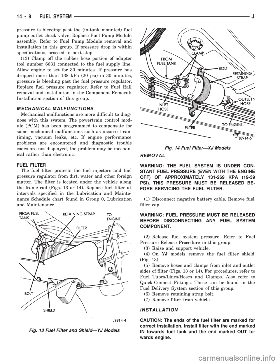
FUEL FILTER
The fuel filter protects the fuel injectors and fuel
pressure regulator from dirt, water and other foreign
matter. The filter is located under the vehicle along
the frame rail (Figs. 13 or 14). Replace fuel filter at
intervals specified in the Lubrication and Mainte-
nance Schedule chart found in Group 0, Lubrication
and Maintenance.
REMOVAL
WARNING: THE FUEL SYSTEM IS UNDER CON-
STANT FUEL PRESSURE (EVEN WITH THE ENGINE
OFF) OF APPROXIMATELY 131-269 KPA (19-39
PSI). THIS PRESSURE MUST BE RELEASED BE-
FORE SERVICING THE FUEL FILTER.
(1) Disconnect negative battery cable. Remove fuel
filler cap.
WARNING: FUEL PRESSURE MUST BE RELEASED
BEFORE DISCONNECTING ANY FUEL SYSTEM
COMPONENT.
(2) Release fuel system pressure. Refer to Fuel
Pressure Release Procedure in this group.
(3) Raise and support vehicle.
(4) On YJ models remove the fuel filter shield
(Fig. 13).
(5) Remove hoses and clamps from inlet and outlet
sides of filter (Figs. 13 or 14). For procedures, refer to
Fuel Tubes/Lines/Hoses and Clamps. Also refer to
Quick-Connect Fittings. These can be found in the
Fuel Delivery System section of this group.
(6) Remove retaining strap bolt.
(7) Remove filter from vehicle.
INSTALLATION
CAUTION: The ends of the fuel filter are marked for
correct installation. Install filter with the end marked
IN towards fuel tank and the end marked OUT to-
wards engine.
Fig. 13 Fuel Filter and ShieldÐYJ Models
Fig. 14 Fuel FilterÐXJ Models
14 - 8 FUEL SYSTEMJ
Page 1446 of 1784
²Noise
²Handling
²Durability
²Tread life
²Traction
²Rolling resistance
²Speed capability
Original equipment tires should be used when re-
placement is needed.
Refer to the placard on the vehicle or the
Owner's Manual for the correct replacement
tire.
Failure to use original or equivalent replacement
tires may adversely affect the handling of the vehi-
cle.
The use of oversize tiresis not recommended.
They may cause interference with vehicle suspension
and steering travel. This can cause tire damage or
failure.
WARNING: FAILURE TO EQUIP THE VEHICLE WITH
TIRES HAVING ADEQUATE LOAD CAPABILITY CAN
RESULT IN SUDDEN TIRE FAILURE.
ROTATION
Tires on the front and rear axles operate at differ-
ent loads and perform different steering, driving, and
braking functions. For these reasons, the tires wear
at unequal rates. They may also develop irregular
wear patterns. These effects can be reduced by rotat-
ing the tires according to the maintenance schedule
in the Owners Manual. This will improve tread life,
traction and maintain a smooth quiet ride.
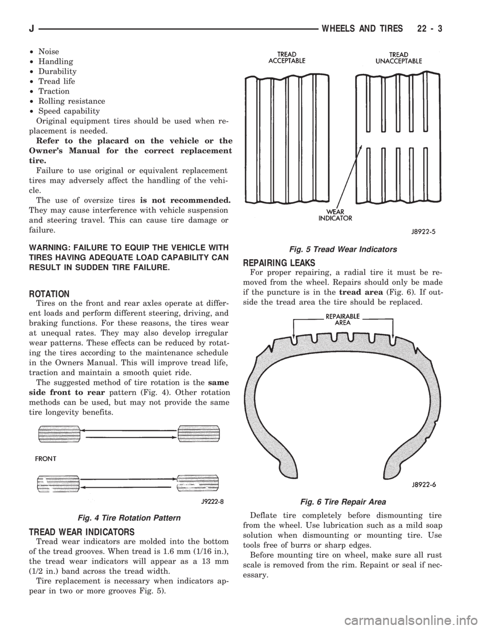
The suggested method of tire rotation is thesame
side front to rearpattern (Fig. 4). Other rotation
methods can be used, but may not provide the same
tire longevity benefits.
TREAD WEAR INDICATORS
Tread wear indicators are molded into the bottom
of the tread grooves. When tread is 1.6 mm (1/16 in.),
the tread wear indicators will appear as a 13 mm
(1/2 in.) band across the tread width.
Tire replacement is necessary when indicators ap-
pear in two or more grooves Fig. 5).
REPAIRING LEAKS
For proper repairing, a radial tire it must be re-
moved from the wheel. Repairs should only be made
if the puncture is in thetread area(Fig. 6). If out-
side the tread area the tire should be replaced.
Deflate tire completely before dismounting tire
from the wheel. Use lubrication such as a mild soap
solution when dismounting or mounting tire. Use
tools free of burrs or sharp edges.
Before mounting tire on wheel, make sure all rust
scale is removed from the rim. Repaint or seal if nec-
essary.
Fig. 4 Tire Rotation Pattern
Fig. 5 Tread Wear Indicators
Fig. 6 Tire Repair Area
JWHEELS AND TIRES 22 - 3
Page 1758 of 1784
LIFTGATE LOCK CYLINDER
REPLACEMENT.......................8P-7
LIFTGATE OPENING WEATHERSTRIP SEAL . . . 23-70
LIFTGATE PILLAR TRIM COVERSÐXJ
VEHICLES.........................23-116
LIFTGATE REMOVAL/INSTALLATION........23-65
LIFTGATE SERVICE INFORMATIONÐXJ
VEHICLES..........................23-65
LIFTGATE SUPPORT ROD BALL
STUD REPLACEMENT.................23-70
LIFTGATE SUPPORT ROD CYLINDER.......23-69
LIFTGATE SUPPORT ROD CYLINDER
DISPOSAL..........................23-70
LIFTGATE TRIM PANEL.................23-66
LIFTGATE WINDOW GLASSÐXJ
VEHICLES..........................23-81
LIFTGATE WIPER.......................8K-5
LIFTGATE WIPER SWITCH REPLACEMENT....8K-6
LIGHT DISPLAY, ABS WARNING............5-3
LIGHT DISPLAY, BRAKE WARNING..........5-4
LIGHTED VANITY MIRROR...............8L-19
LIGHTED VANITY MIRROR TROUBLE
DIAGNOSIS.........................8L-19
LIGHTS, BRAKE WARNING.................5-1
LIGHTS (CANADA ONLY), DAYTIME
RUNNING...........................8L-16
LIGHTS, SYSTEM WARNING..............5-42
LIMITED SLIP DIFFERENTIAL...............3-8
LIMITS, AW-4 OIL PUMP WEAR.........21-325
LINE CLUSTER, HIGH...................8E-12
LINE CLUSTER, LOW...................8E-11
LINE FITTINGS, TRANSMISSION COOLER . . 21-187
LINERS, REAR WHEELHOUSE FLARES.....23-18
LINERS, WHEELHOUSE SPLASH.........23-146
LINES AND FITTINGS, SERVICING
TRANSMISSION COOLER.............21-106
LINK CONNECTORÐPCM INPUT, DATA.....14-20
LINK CONNECTORÐPCM OUTPUT, DATA . . . 14-24
LINK, DRAG.....................19-14,19-17
LINK REPLACEMENT, FUSIBLE............8W-4
LINKAGE ADJUSTMENT, SHIFT....21-275,21-296
LINKAGE ADJUSTMENT (YJ), GEARSHIFT . . . 21-96
LINKAGE AND BALL STUDS, STEERING.....0-30
LINKAGE FLUID, CLUTCH..................6-1
LINKAGE, GEARSHIFT..................21-70
LINKAGE INSTALLATION, CLUTCH
HYDRAULIC..........................6-12
LINKAGE REMOVAL, CLUTCH HYDRAULIC....6-11
LINKAGEÐXJ, STEERING..........19-14,19-73
LINKAGEÐYJ, STEERING..........19-17,19-73
LINKS, FUSIBLE.......................8W-3
LOAD DATA, VEHICLE................INTRO.-3
LOAD DATA, XJ VEHICLE.............INTRO.-5
LOAD DATA, YJ-VEHICLE.............INTRO.-6
LOAD TEST, BATTERY...................8A-4
LOCATING A SYSTEM...................8W-2
LOCATIONS, SPLICE..............8W-2,8W-53
LOCATIONS, TRANSMISSION SWITCH
AND PLUG..........................21-33
LOCATIONS, XJ RHD SPLICE............8W-67
LOCATIONS, XJ SPLICE................8W-59
LOCATIONS, YJ SPLICE................8W-53
LOCK COMPONENT OVERHAUL,
ADAPTER HOUSING AND PARK........21-120
LOCK COMPONENT REPLACEMENT,
PARK .............................21-102
LOCK CYLINDER, DOOR KEY.............23-54
LOCK CYLINDER, FULL-METAL DOOR
KEY ..............................23-178
LOCK CYLINDER REPLACEMENT,
LIFTGATE............................8P-7
LOCK CYLINDER, TAILGATE.............23-160
LOCK CYLINDER/STRIKER, LIFTGATE
LATCH/KEY.........................23-68
LOCK CYLINDERS, KEY............23-2,23-132
LOCK HANDLE, FULL-METAL DOOR.......23-175
LOCK, HYDROSTATIC.....................9-4
LOCK RODS, DOOR INSIDE LATCH
RELEASE...........................23-57
LOCK SWITCH, PASSENGER DOOR
.........8P-5
LOCK SWITCHÐ2-DOOR LEFT HAND
DRIVE, DRIVERS DOOR POWER
..........8P-2
LOCK SWITCHÐ2-DOOR RIGHT HAND
DRIVE,DRIVERS DOOR POWER
..........8P-3
LOCK SWITCHÐ4-DOOR, DRIVERS
DOOR POWER
........................8P-4LOCKS, DIAGNOSING POWER DOOR . . . 8P-1,8P-9
LOCKS, POWER; ELECTRICAL.............8A-1
LOCKS, POWER; POWER DOOR LOCKS.....8P-1
LOCKS, POWER DOOR..................8P-10
LOCK/UNLOCK RELAY REPLACEMENT,
DOOR.............................8P-12
LOOP MODES OF OPERATION, OPEN
LOOP/CLOSED.......................14-27
LOOP/CLOSED LOOP MODES OF
OPERATION, OPEN...................14-27
LOSS OF SENSOR INPUT..................5-3
LOW FUEL WARNING INOPERATIVE........8E-4
LOW FUEL WARNING LAMP..............8E-2
LOW LINE CLUSTER...................8E-11
LOW SPEED KNOCK; FRONT SUSPENSION
AND AXLE...........................2-17
LOW SPEED KNOCK; REAR SUSPENSION
AND AXLES...........................3-8
LOW WASHER INDICATOR INOPERATIVE....8E-4
LOWER SUSPENSION ARM...............2-11
LUBRICANT AND REPLACEMENT PARTS,
RECOMMENDED.......................0-3
LUBRICANT CHANGE; FRONT
SUSPENSION AND AXLE................2-22
LUBRICANT CHANGE; REAR SUSPENSION
AND AXLES......................3-13,3-30
LUBRICANT, RECOMMENDED.............21-2
LUBRICANT SPECIFICATIONS, BODY........0-35
LUBRICANT SPECIFICATIONS; FRONT
SUSPENSION AND AXLE................2-20
LUBRICANT SPECIFICATIONS; REAR
SUSPENSION AND AXLES...........3-11,3-30
LUBRICANT, TRANSFER CASE.....21-273,21-294
LUBRICANT, TRANSMISSION.............21-33
LUBRICANTS, CHASSIS COMPONENT
AND WHEEL BEARING.................0-30
LUBRICANTS, CLASSIFICATION OF..........0-2
LUBRICATION, CLUTCH COMPONENT........6-1
LUBRICATION, COMPONENTS
REQUIRING NO........................0-3
LUG NUT, WHEEL......................22-11
LUGGAGE RACKÐXJ VEHICLES..........23-32
MAGNETIC CLUTCH....................24-18
MAIN BEARING FITTING CHART.......9-43,9-83
MAIN BEARINGS, CRANKSHAFT.......9-40,9-80
MAIN OIL SEALS, REAR..............9-44,9-84
MAINTENANCE, BATTERY................8B-1
MAINTENANCE, ENGINE..................0-13
MAINTENANCE SCHEDULES...............0-5
MAINTENANCE, SEVERE SERVICE...........0-5
MAJOR COMPONENT IDENTIFICATION . . . INTRO.-3
MALFUNCTION INDICATOR LAMP
(CHECK ENGINE); INSTRUMENT PANEL
AND GAUGESÐXJ................8E-2,8E-4
MALFUNCTION INDICATOR LAMP
(CHECK ENGINE); INSTRUMENT PANEL
AND GAUGESÐYJ...................8E-16
MALFUNCTION INDICATOR LAMPÐPCM
OUTPUT............................14-26
MANIFOLDÐ2.5L ENGINE, ENGINE
EXHAUST............................11-7
MANIFOLDÐ2.5L ENGINE, INTAKE.........11-8
MANIFOLDÐ4.0L ENGINE, ENGINE
EXHAUST............................11-7
MANIFOLDÐ4.0L ENGINE, INTAKE
.........11-9
MANIFOLD ABSOLUTE PRESSURE (MAP)
SENSOR; FUEL SYSTEM
...............14-57
MANIFOLD ABSOLUTE PRESSURE (MAP)
SENSOR; IGNITION SYSTEMS
......8D-5,8D-27
MANIFOLD ABSOLUTE PRESSURE (MAP)
SENSORÐPCM INPUT
................14-21
MANIFOLD ABSOLUTE PRESSURE (MAP)
SENSOR TEST; FUEL SYSTEM
..........14-44
MANIFOLD ABSOLUTE PRESSURE (MAP)
SENSOR TEST; IGNITION SYSTEMS
......8D-14
MANIFOLD AIR TEMPERATURE SENSOR,
INTAKE
........................8D-5,8D-27
MANIFOLD AIR TEMPERATURE
SENSOR TEST, INTAKE
................8D-14
MANIFOLD ASSEMBLY, PRESSURE
GAUGE
..............................24-2
MANIFOLD, INTAKE
....................14-57
MANIFOLD LEAKAGE DIAGNOSIS, INTAKE
.....9-5
MANUAL FIRST GEAR (1) POSITION,
HYDRAULIC FLOW IN
.................21-94MANUAL SECOND (2) RANGE,
HYDRAULIC FLOW IN.................21-93
MANUAL SHIFTING TEST...............21-168
MANUAL STEERING GEAR..........19-35,19-73
MANUAL STEERING GEAR
SPECIFICATIONS.....................19-44
MANUAL STEERING GEARÐYJ VEHICLES....0-32
MANUAL STEERING SYSTEM DIAGNOSIS . . . 19-36
MANUAL TRANSMISSION................0-22
MANUAL TRANSMISSION, AX 15.........21-32
MANUAL TRANSMISSION, AX 4/5..........21-1
MANUAL TRANSMISSION, SELECTIVE
SNAP RING CHARTÐAX 15...........21-321
MANUAL TRANSMISSION, TORQUE
SPECIFICATIONSÐ AX 15.............21-320
MANUAL VALVE SHAFT OVERHAUL.......21-205
MANUAL VALVE SHAFT SEAL
REPLACEMENT.....................21-178
MARKER LAMP BULB REPLACEMENT,
SIDE...............................8L-7
MASTER CYLINDER.....................5-40
MASTER CYLINDER INSTALLATION.....5-20,5-50
MASTER CYLINDER OVERHAUL...........5-20
MASTER CYLINDER REMOVAL........5-20,5-50
MASTER CYLINDER, STANDARD...........5-20
MASTER CYLINDER/POWER BOOSTER
TEST...............................5-11
MATCH MOUNTING TIRES................22-7
MATERIAL, BRAKELINING.................5-1
MATS, CARPET/FLOOR.................23-198
MATS, CARPETS AND FLOOR...........23-129
MEASUREMENT AND ADJUSTMENT,
DIFFERENTIAL SHIM PACK..............2-42
MEASUREMENT, DIFFERENTIAL AND
PINION; FRONT SUSPENSION AND AXLE....2-38
MEASUREMENT, DIFFERENTIAL AND
PINION; REAR SUSPENSION AND AXLES....3-20
MEASUREMENT, UNIVERSAL JOINT
ANGLE..............................16-4
MEASUREMENTS AND ADJUSTMENTS,
ALIGNMENT...........................2-6
MEASURING WITH PLASTIGAGE............9-3
METALS, PAINT REPAIR ON GALVANIZED . . 23-202
METRIC SYSTEM NOTATION...........INTRO.-8
METRIC, THREAD NOTATIONÐSAE.....INTRO.-9
(MFI)ÐCOMPONENT DESCRIPTION/
SYSTEM OPERATION, MULTI-
PORT FUEL INJECTION................14-17
(MFI)ÐCOMPONENT REMOVAL/
INSTALLATION, MULTI-PORT FUEL
INJECTION..........................14-54
(MFI)ÐGENERAL DIAGNOSIS,
MULTI-PORT FUEL INJECTION..........14-32
MINI-FLOOR CONSOLEÐXJ VEHICLES....23-124
MIRROR (EXTERNAL), HALF METAL
DOOR
............................23-158
MIRROR, INTERIOR REARVIEW
...........23-74
MIRROR, LIGHTED VANITY
..............8L-19
MIRROR, REARVIEW
..................23-183
MIRROR REPLACEMENT, POWER
..........8T-4
MIRROR RETAINING BRACKET,
REARVIEW
.........................23-183
MIRROR SUPPORT BRACKET
REPLACEMENT, INTERIOR REARVIEW
....23-75
MIRROR SWITCH, POWER
................8T-2
MIRROR SWITCH REPLACEMENT,
POWER
.............................8T-4
MIRROR SWITCH TESTING, POWER
........8T-2
MIRROR TROUBLE DIAGNOSIS, LIGHTED
VANITY
............................8L-19
MIRRORS, EXTERNAL
..................23-31
MIRRORS, POWER
.....................8A-1
MISS, INJECTOR DIAGNOSISÐVEHICLE
RUNS ROUGH AND/OR HAS A
..........14-49
MODE, ABS OPERATION IN ANTILOCK
BRAKING
............................5-43
MODE, ABS OPERATION IN NORMAL
BRAKING
............................5-43
MODE, VEHICLE RESPONSE IN
ANTILOCK
............................5-3
MODEL 30 AXLE AND TUBE AXLE
(2WD)
..............................2-20
MODEL 30 FRONT AXLE
.............2-46,2-47
MODEL 35, REAR AXLE
..........3-11,3-28,3-50
14 INDEXJ
Description Group-Page Description Group-Page Description Group-Page