1994 JEEP CHEROKEE fuses
[x] Cancel search: fusesPage 281 of 1784

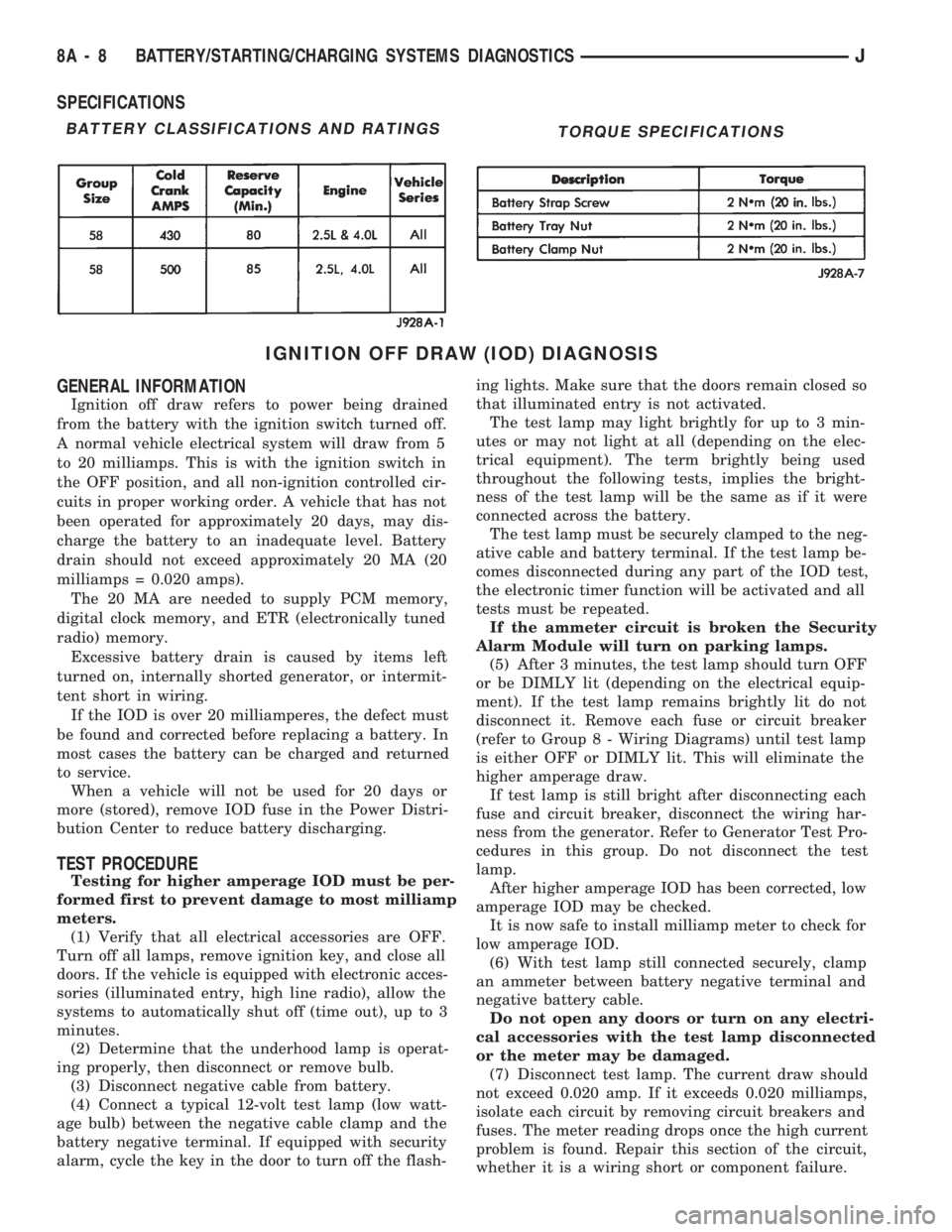
SPECIFICATIONS
IGNITION OFF DRAW (IOD) DIAGNOSIS
GENERAL INFORMATION
Ignition off draw refers to power being drained
from the battery with the ignition switch turned off.
A normal vehicle electrical system will draw from 5
to 20 milliamps. This is with the ignition switch in
the OFF position, and all non-ignition controlled cir-
cuits in proper working order. A vehicle that has not
been operated for approximately 20 days, may dis-
charge the battery to an inadequate level. Battery
drain should not exceed approximately 20 MA (20
milliamps = 0.020 amps).
The 20 MA are needed to supply PCM memory,
digital clock memory, and ETR (electronically tuned
radio) memory.
Excessive battery drain is caused by items left
turned on, internally shorted generator, or intermit-
tent short in wiring.
If the IOD is over 20 milliamperes, the defect must
be found and corrected before replacing a battery. In
most cases the battery can be charged and returned
to service.
When a vehicle will not be used for 20 days or
more (stored), remove IOD fuse in the Power Distri-
bution Center to reduce battery discharging.
TEST PROCEDURE
Testing for higher amperage IOD must be per-
formed first to prevent damage to most milliamp
meters.
(1) Verify that all electrical accessories are OFF.
Turn off all lamps, remove ignition key, and close all
doors. If the vehicle is equipped with electronic acces-
sories (illuminated entry, high line radio), allow the
systems to automatically shut off (time out), up to 3
minutes.
(2) Determine that the underhood lamp is operat-
ing properly, then disconnect or remove bulb.
(3) Disconnect negative cable from battery.
(4) Connect a typical 12-volt test lamp (low watt-
age bulb) between the negative cable clamp and the
battery negative terminal. If equipped with security
alarm, cycle the key in the door to turn off the flash-ing lights. Make sure that the doors remain closed so
that illuminated entry is not activated.
The test lamp may light brightly for up to 3 min-
utes or may not light at all (depending on the elec-
trical equipment). The term brightly being used
throughout the following tests, implies the bright-
ness of the test lamp will be the same as if it were
connected across the battery.
The test lamp must be securely clamped to the neg-
ative cable and battery terminal. If the test lamp be-
comes disconnected during any part of the IOD test,
the electronic timer function will be activated and all
tests must be repeated.
If the ammeter circuit is broken the Security
Alarm Module will turn on parking lamps.
(5) After 3 minutes, the test lamp should turn OFF
or be DIMLY lit (depending on the electrical equip-
ment). If the test lamp remains brightly lit do not
disconnect it. Remove each fuse or circuit breaker
(refer to Group 8 - Wiring Diagrams) until test lamp
is either OFF or DIMLY lit. This will eliminate the
higher amperage draw.
If test lamp is still bright after disconnecting each
fuse and circuit breaker, disconnect the wiring har-
ness from the generator. Refer to Generator Test Pro-
cedures in this group. Do not disconnect the test
lamp.
After higher amperage IOD has been corrected, low
amperage IOD may be checked.
It is now safe to install milliamp meter to check for
low amperage IOD.
(6) With test lamp still connected securely, clamp
an ammeter between battery negative terminal and
negative battery cable.
Do not open any doors or turn on any electri-
cal accessories with the test lamp disconnected
or the meter may be damaged.
(7) Disconnect test lamp. The current draw should
not exceed 0.020 amp. If it exceeds 0.020 milliamps,
isolate each circuit by removing circuit breakers and
fuses. The meter reading drops once the high current
problem is found. Repair this section of the circuit,
whether it is a wiring short or component failure.
BATTERY CLASSIFICATIONS AND RATINGSTORQUE SPECIFICATIONS
8A - 8 BATTERY/STARTING/CHARGING SYSTEMS DIAGNOSTICSJ
Page 288 of 1784

OPERATIONAL CHECK WITH VOLTMETER
When the ignition switch is turned to the ON po-
sition, battery potential will register on the voltme-
ter. During engine cranking a lower voltage will
appear on the meter. With the engine running, a
voltage reading higher than the first reading (igni-
tion in ON) should register.
DIAGNOSTIC PROCEDURES
If the indicator operates abnormally, or if an un-
dercharged or overcharged battery condition occurs,
the following procedures may be used to diagnose the
charging system.
Remember that an undercharged battery is often
caused by:
²accessories being left on overnight
²or by a defective switch which allows a bulb, such
as a liftgate or glove box light, to stay on (refer to
Ignition Off Draw Diagnosis).
VISUAL INSPECTION
²Inspect condition of battery cable terminals, bat-
tery posts, connections at engine block, starter motor
solenoid and relay. They should be clean and tight.
Repair as required.
²Inspect all fuses in the fuse block for tightness in
receptacles. They should be properly installed and
tight. Repair or replace as required.²Inspect the electrolyte level in the battery and add
water if necessary.
²Inspect generator mounting bolts for tightness. Re-
place or torque bolt as required. Refer to Torque
Specifications in Battery/Starter/Generator Service.
²Inspect generator drive belt condition and tension.
Tension or replace belt as required. Refer to Belt
Tension Specifications in Battery/Starter/Generator
Service.
²Inspect connection at generator B+ output. It
should be clean and tight. Repair as required.
GENERATOR OUTPUT WIRE RESISTANCE
TEST
Generator output wire resistance test will show
amount of voltage drop across generator output wire
between generator battery terminal and battery pos-
itive post.
PREPARATION
(1) Before starting test make sure vehicle has a
fully charged battery. Test and procedures on how to
check for a fully charged battery are shown in Bat-
tery Test Procedures.
(2) Turn OFF ignition switch.
(3) Disconnect negative cable from battery.
(4) Disconnect generator output wire from genera-
tor output battery terminal.
Fig. 2 Generator Output Wire Resistance Test (Typical)
JBATTERY/STARTING/CHARGING SYSTEMS DIAGNOSTICS 8A - 15
Page 453 of 1784

A voltage drop of one-half the full amount, approx-
imately 6 volts, indicates a good grid or closed cir-
cuit.
A voltage drop of 12 volts at the centerline indi-
cates a break in the grid between the positive volt-
meter lead and the ground.
No voltage drop (0 volts) at the centerline indicates
a break in the grid between the centerline and the
voltage source or lead.
The exact location of the break can be pinpointed
by moving positive voltmeter lead to the left or right
along grid. An abrupt change in the voltage reading
will be noticed. The break is at that point in the
grid.
REAR WINDOW DEFOGGER GRID REPAIR
Locate the broken or open grid.
Use the grid repair kit (available as a service part)
by using the following procedure:
(1) Mark the location of the broken or open grid on
the exterior surface of the glass using a suitable
marking pencil.
(2) Lightly rub the area to be repaired (inside the
rear window) using fine steel wool. Clean the area
with alcohol.
(3) Attach two strips of masking tape to the inside
surface of the rear window (above and below the
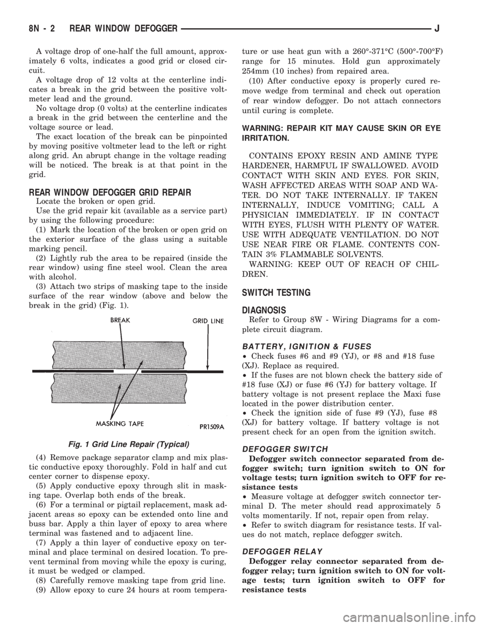
break in the grid) (Fig. 1).
(4) Remove package separator clamp and mix plas-
tic conductive epoxy thoroughly. Fold in half and cut
center corner to dispense epoxy.
(5) Apply conductive epoxy through slit in mask-
ing tape. Overlap both ends of the break.
(6) For a terminal or pigtail replacement, mask ad-
jacent areas so epoxy can be extended onto line and
buss bar. Apply a thin layer of epoxy to area where
terminal was fastened and to adjacent line.
(7) Apply a thin layer of conductive epoxy on ter-
minal and place terminal on desired location. To pre-
vent terminal from moving while the epoxy is curing,
it must be wedged or clamped.
(8) Carefully remove masking tape from grid line.
(9) Allow epoxy to cure 24 hours at room tempera-ture or use heat gun with a 260É-371ÉC (500É-700ÉF)
range for 15 minutes. Hold gun approximately
254mm (10 inches) from repaired area.
(10) After conductive epoxy is properly cured re-
move wedge from terminal and check out operation
of rear window defogger. Do not attach connectors
until curing is complete.
WARNING: REPAIR KIT MAY CAUSE SKIN OR EYE
IRRITATION.
CONTAINS EPOXY RESIN AND AMINE TYPE
HARDENER, HARMFUL IF SWALLOWED. AVOID
CONTACT WITH SKIN AND EYES. FOR SKIN,
WASH AFFECTED AREAS WITH SOAP AND WA-
TER. DO NOT TAKE INTERNALLY. IF TAKEN
INTERNALLY, INDUCE VOMITING; CALL A
PHYSICIAN IMMEDIATELY. IF IN CONTACT
WITH EYES, FLUSH WITH PLENTY OF WATER.
USE WITH ADEQUATE VENTILATION. DO NOT
USE NEAR FIRE OR FLAME. CONTENTS CON-
TAIN 3% FLAMMABLE SOLVENTS.
WARNING: KEEP OUT OF REACH OF CHIL-
DREN.
SWITCH TESTING
DIAGNOSIS
Refer to Group 8W - Wiring Diagrams for a com-
plete circuit diagram.
BATTERY, IGNITION & FUSES
²Check fuses #6 and #9 (YJ), or #8 and #18 fuse
(XJ). Replace as required.
²If the fuses are not blown check the battery side of
#18 fuse (XJ) or fuse #6 (YJ) for battery voltage. If
battery voltage is not present replace the Maxi fuse
located in the power distribution center.
²Check the ignition side of fuse #9 (YJ), fuse #8
(XJ) for battery voltage. If battery voltage is not
present check for an open from the ignition switch.
DEFOGGER SWITCH
Defogger switch connector separated from de-
fogger switch; turn ignition switch to ON for
voltage tests; turn ignition switch to OFF for re-
sistance tests
²Measure voltage at defogger switch connector ter-
minal D. The meter should read approximately 5
volts momentarily. If not, repair open from relay.
²Refer to switch diagram for resistance tests. If val-
ues do not match, replace defogger switch.
DEFOGGER RELAY
Defogger relay connector separated from de-
fogger relay; turn ignition switch to ON for volt-
age tests; turn ignition switch to OFF for
resistance tests
Fig. 1 Grid Line Repair (Typical)
8N - 2 REAR WINDOW DEFOGGERJ
Page 488 of 1784

CHIME/BUZZER WARNING SYSTEMS
CONTENTS
page page
GENERAL.............................. 1
IGNITION KEY WARNING SWITCH REPLACEMENT.4OPERATION/DIAGNOSIS.................. 1
GENERAL
The buzzer or optional chime module is mounted on
the left side of the fuse block (above and to the left of
the brake/clutch pedal). The buzzer or chime sounds
an audible warning tone in any of the following con-
ditions:
²Vehicle lights are ON when the ignition has been
switched OFF and the key is removed and then the
driver's door is opened (except YJ).²The key is in the ignition and the driver's door is
open (On some vehicles, the buzzer will not sound if
the ignition switch is in the ON position).
²The ignition is switched ON and the driver's seat
belt is not buckled. Buzzer will quit after 4 to 8 sec-
onds. Besides the buzzer, a seat belt indicator lamp
turns on as a reminder to fasten seat belt.
OPERATION/DIAGNOSIS
OPERATION
Battery voltage for module operation is supplied to
two pins. Voltage is always present at pin 7. Pin 1
receives voltage when the ignition switch is in the
ON or START position.
SEAT BELT WARNING
The seat belt warning system uses both visual and
audible signals. These consist of a buzzer that is part
of a combined seat belt and key warning buzzer and
a red light on the instrument panel.
The system will always illuminate the seat belt
warning lamp for four to eight seconds when the ig-
nition switch is turned to the ON position. Also, only
if the driver does not fasten his seat belt, the buzzer
will sound during the same time interval. Passenger
belts are not connected to the system.
A timed buzzer-relay is used to operate the system
for the time period. It has a time delay mechanism
and buzzer assembly. Only the driver's seat belt
buckle has a switch that is connected to the system.
KEY-IN-IGNITION WARNING
To sound the key-in-ignition warning, the following
must occur:
²the ignition key warning switch must be closed
²the driver's door jamb switch must be closed.
These conditions ground pin 6 of the module. These
switches are closed when the key is in the ignition
and the driver's door is open.On some vehicles the chime/buzzer will not
sound if the door is open and the key is in the
ON position.
LIGHTS-ON WARNING (EXCEPT YJ)
To sound the lights-on warning, the following must
occur:
²the headlamp switch must be closed
²the driver's door jamb switch must be closed.
These conditions ground pin 6 of the module. These
switches are closed when the headlamp switch is ON
and the driver's door is open.
DIAGNOSIS
If the buzzer/chime unit does not operate as de-
scribed, check the two fuses for pins 1 and 7 (Figs. 1
and 2) and replace as required. If the fuses are not
defective, perform the following tests to determine if
the problem is in the module or in the wiring. Using
a flat head screwdriver, release the locking plastic
clip while carefully pulling out the module. Plug in a
known good module and check its operation. If the
problem is not corrected by replacing the module, re-
move the module and continue as follows:
VOLTAGE TESTS
Ignition in ON position, measure between the
following pins and vehicle ground.
²Measure voltage at buzzer/chime module connector
pin 1. Meter should read battery voltage. If not, re-
pair open to ignition switch.
Turn ignition OFF and remove the key from the ig-
nition.
JCHIME/BUZZER WARNING SYSTEMS 8U - 1
Page 494 of 1784

WIRING DIAGRAMS
CONTENTS
page page
FUSE CHARTS AND RELAY BANKS......... 8
GENERAL INFORMATION.................. 1
SPLICE LOCATIONS..................... 53
WIRING AND COMPONENT IDENTIFICATION . 13WIRING DIAGRAMS XJ.................. 149
WIRING DIAGRAMS XJ RHD............. 271
WIRING DIAGRAMS YJ.................. 73
GENERAL INFORMATION
INDEX
page page
Circuit Identification........................ 2
Component Identification.................... 2
Connector and Terminal Assembly Replacement . . 5
Connector Replacement.................... 4
Connectors.............................. 3
Fusible Link Replacement................... 4
Fusible Links............................. 3
Locating A System........................ 2Secondary Ignition Wiring................... 1
Splice Locations.......................... 2
Symbols, Fuses and Abbreviations............ 6
Terminal Replacement...................... 5
Troubleshooting Wiring Problems.............. 3
Wire Code Identification.................... 2
Wiring Diagram Sheets and Indexes........... 1
Wiring Repair............................ 4
The wiring diagrams contain the latest information
at the time of publication.
Throughout this group references may be made to
a particular vehicle by letter or number designation.
A chart showing the breakdown of these designations
is included in the Introduction Section at the front of
this service manual.
SECONDARY IGNITION WIRING
Secondary ignition wiring is shown in Figures 1
and 2. For additional information on ignition systems
or distributor operation refer to Group 8D Ignition
Systems.
WIRING DIAGRAM SHEETS AND INDEXES
The diagrams are organized to show the basic ve-
hicle and all of its options. Add-on or non-factory op-
tions are not covered. The diagram pages are
identified by a sheet number which is located at the
lower right or left hand corner of each sheet.Page
numbers at the top of each page do not apply to
diagram sheets.
Diagram sheets show all information relating to
the system. This includes feeds, grounds, switch in-
ternal circuity, connectors, splices, and pin identifica-
tion for controllers and modules. All components,switches, and relays are shown in the at rest position
with the key removed from the ignition and the doors
closed.
In certain instances a wire may be referenced to
another sheet. When this happens, the wire will be
identified as to where it is going.
The index used for the diagrams is located at the
beginning of the section. The main system and all re-
lated components are covered.
Fig. 1 Secondary Ignition Wiring 2.5L
JWIRING DIAGRAMS 8W - 1
Page 495 of 1784

WIRE CODE IDENTIFICATION
Each wire shown in the diagrams contains a code
(Fig. 3) which identifies the main circuit, part of the
main circuit, gauge of wire, and color. The color is
shown as a two letter code which can be identified by
referring to the Wire Color Code Chart (Fig. 4). If the
wire has a tracer and it is a standard color an aster-
isk will follow the main wire color. If the tracer is
non-standard the main wire color will have a slash (/)
after it followed by the tracer color.
CIRCUIT IDENTIFICATION
All circuits in the diagrams use an alpha/numeric
code to identify the wire and its function. To identify
which circuit code applies to a system, refer to the
Circuit Identification Code Chart. This chart shows
the main circuits only and does not show the second-
ary codes that may apply to some models.
LOCATING A SYSTEM
To locate a system or component in the diagrams,
refer to the alphabetical index at the front of the di-
agrams. Determine the diagram sheet number. Sheet
numbers are located at the lower right or left handcorner of each sheet.Page numbers at the top of
the page do not apply to diagram sheets.
The index identifies the main system and all com-
ponents that relate to that system. There are also
sections of the index that identify specific compo-
nents only (for example modules, lamps, etc.). Refer
to a components name in the index if you are unclear
as to what a system may be called.
Diagram sheets are arranged starting with the bat-
tery and fuses. Then working into charging, starting,
and ignition systems. After this they start at the
front of the vehicle and work to rear. The diagrams
end with connector identification pages.
COMPONENT IDENTIFICATION
When looking for a components location in the vehicle
refer to the Component Identification section index.
This section shows the wire harness routing and the
components location in the vehicle. When using this sec-
tion refer to the wiring diagrams for the general loca-
tion of the component. Then use the component
identification index to locate the proper figure number.
SPLICE LOCATIONS
Splice locations are indicated in the diagrams by a
diamond with a splice circuit code within it (Fig. 5
example 1). If there is more than one splice per cir-
cuit a small box will be connected to it with the
splice number in it (Fig. 5 example 2).
To locate a splice in the wiring harness determine
the splice number from the wiring diagrams then re-
fer to the splice location index. This section shows
the general location of the splice in the harness.
Fig. 2 Secondary Ignition Wiring 4.0L
Fig. 3 Wire Color Code Identification
Fig. 4 Wire Color Code Chart
8W - 2 WIRING DIAGRAMSJ
Page 499 of 1784

(10) Spread the strands of the wire apart on each
of the exposed wires (Fig. 7 example 1).
(11) Push the two ends of wire together until the
strands of wire are close to the insulation (Fig. 7 ex-
ample 2).
(12) Twist the wires together (Fig. 7 example 3).
(13) Solder the connection together using rosin
core type solder only.Do not use acid core solder.
(14) Center the heat shrink tubing over the joint
and heat using a heat gun. Heat the joint until the
tubing is tightly sealed and sealant comes out of both
ends of the tubing.
(15) Insert the repaired wire into the connector.
(16) Install the connector locking wedge and recon-
nect the connector to its mating half.
(17) Re-tape the wire harness starting 1-1/2 inches
behind the connector and 2 inches past the repair.(18) Connect battery and test affected systems.
SYMBOLS, FUSES AND ABBREVIATIONS
Various symbols are used throughout the wiring di-
agrams. These symbols can be identified by referring
to the symbol identification chart (Fig. 11).
Certain abbreviations are also used in the dia-
grams. These have been developed in such a way
that there meaning should be clear. For fuse block,
relay bank, and power distribution center informa-
tion refer to the fuse charts and relay bank index.
CAUTION: When replacing a blown fuse it is impor-
tant to replace it with a fuse having the correct am-
perage rating. The use of a fuse with a rating other
than indicated may result in an electrical overload.
If a proper rated fuse continues to blow, it indicates
a problem that should be corrected.
8W - 6 WIRING DIAGRAMSJ
Page 567 of 1784

Wiring Diagram Name Sheet Number
Left Fog Lamp.............................27
Left Headlamp.............................27
Left Park and Turn Signal Lamp.................27
Left Side Marker Lamp.......................27
Right Fog Lamp............................28
Right Headlamp............................28
Right Park and Turn Signal Lamp................28
Right Side Marker Lamp......................28
Fuel Gauge................................44
Fuel Injection Ignition System
2.5L Engine.................11, 12, 13, 14, 15, 16
Automatic Shut Down Relay....................11
Camshaft Position Sensor.....................12
Crankshaft Position Sensor.....................12
Data Link Connector.........................13
Engine Coolant Temperature Sensor...............15
Fuel Injectors.............................14
Fuel Pump Relay...........................11
Heated Oxygen Sensor.......................11
Idle Air Control Motor........................14
Ignition Coil..............................13
Intake Air Temperature Sensor..................15
MAP Sensor..............................15
Power Steering Switch.......................14
Powertrain Control Module (PCM) . . .11, 12, 13, 14, 15, 16
Throttle Position (Sensor).....................15
Vehicle Speed Sensor........................12
Fuel Injection Ignition System
4.0L Engine.................17, 18, 19, 20, 21, 22
Automatic Shut Down Relay....................17
Camshaft Position Sensor.....................18
Crankshaft Position Sensor.....................18
Data Link Connector.........................19
Engine Coolant Temperature Sensor...............21
Fuel Injectors.............................20
Fuel Pump Relay...........................17
Heated Oxygen Sensor.......................17
Idle Air Control Motor........................20
Ignition Coil..............................19
Intake Air Temperature Sensor..................21
MAP Sensor..............................21
Powertrain Control Module (PCM) . . .17, 18, 19, 20, 21, 22
Throttle Position (Sensor).....................21
Vehicle Speed Sensor........................18
Fuel Injectors............................14, 20
Fuel Pump Relay..........................11, 17
Fuel Tank System............................55
Fuel Tank Sending Unit.........................55
Fuse Application Chart........................1,2
Fuses
1 .................................2,10,37
3 ..............................1,30,34,36
4 .................................2,10,34
5 ..............................2,10,13,19
6 .................................1,30,53
7 ..............................2,10,24,46
8 ...................................1,29
9 .................................2,10,36Wiring Diagram Name Sheet Number
10 ...................................1,31
11 .............................2,10,38,39
12 ...........................2,10,47,48,50
F13 ..................................2,58
F15 ..............................2,4,6,33
F16 ............................2,4,6,8,35
Fuse Panel..............................61, 62
Gauge Package Connector.......................43
Gauges
Electronic Speedometer.......................42
Electronic Tachometer........................42
Engine Coolant Temperature Gauge...............44
Engine Oil Pressure Gauge.....................44
Fuel Gauge...............................44
Voltmeter................................44
Generator................................3,5
Hazard Signal Flasher..........................34
Headlamps.........................25, 26, 27, 28
Headlamp Switch........................1,29,30
Dimmer Switch............................29
Headlamp Switch...........................29
Heated Oxygen Sensor......................11, 17
Heated Rear Window Relay......................54
Heated Rear Window Switch.....................53
Heated Rear Window System..................53, 54
Heated Rear Window Grid.....................53
Heated Rear Window Relay....................54
Heated Rear Window Switch....................53
Timer..................................54
Heater Control Panel Illumination..................32
Heater System..............................47
Blower Motor.............................47
Blower Resistor............................47
Blower Switch.............................47
Heater/Off Switch...........................47
Horn.....................................33
Horn Brush/Slip Ring........................33
Horn Relay...............................33
Horn Switch..............................33
Hydraulic Actuation Unit........................58
Idle Air Control Motor.......................14, 20
Ignition Coil.............................13, 19
Ignition Key Warning Switch.....................36
Ignition Switch..........................2,9,10
Instrument Panel Illumination Lamps................32
Intake Air Temperature Sensor.................15, 21
Intermittent Wiper Module.......................40
Intermittent Wiper System....................39, 40
Intermittent Wiper Module.....................40
Park Switch..............................39
Washer Pump.............................39
Wiper Motor..............................39
Wiper/Washer Switch........................40
W/Wiper Circuit Breaker (5.3 Amp)...............39
Lamps
Center High Mounted Stop Lamps................52
Dome Lamp..............................35
Instrument Panel Illumination Lamp...............32
8W - 74 WIRING DIAGRAMSJ