1994 JEEP CHEROKEE service indicator
[x] Cancel search: service indicatorPage 3 of 1784
ROUTINE SERVICE
The following routine vehicle service is highly rec-
ommended on a monthly basis.
TIRESÐInspect the tires for unusual wear/damage
and determine if the inflation pressure is acceptable
for the vehicle load.
BATTERYÐInspect and clean the terminals.
Tighten the terminals, if necessary.
FLUIDSÐDetermine if the coolant, brake fluid,
power steering, automatic transmission, and clutch
fluid level are acceptable. Add fluid, if necessary.
LIGHTS/ELECTRICALÐTest all the electrically
operated systems in the vehicle for proper operation.
It is also recommended that the engine oil level
and the windshield washer fluid level be deter-
mined (and corrected) during each fuel fill-up.
FUEL REQUIREMENTS
All Jeeptengines require the use of unleaded gas-
oline. In addition, the fuel must have a minimum oc-
tane rating of 87.
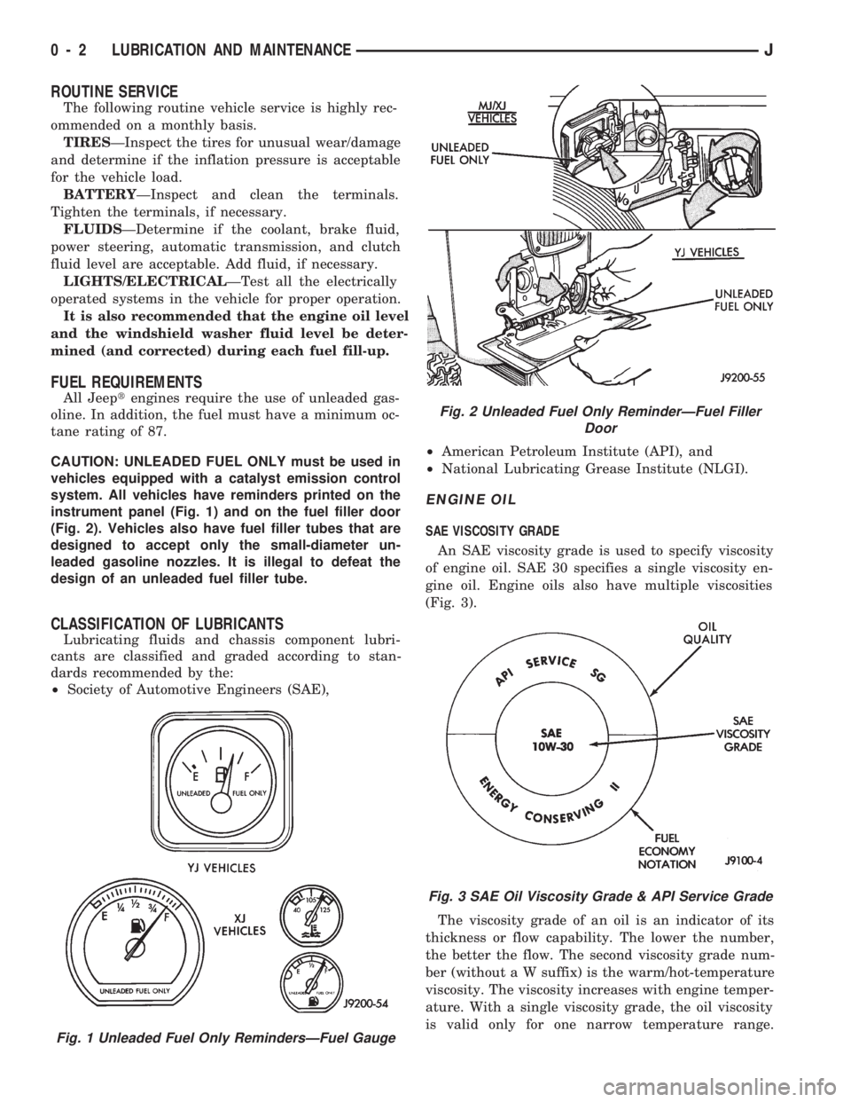
CAUTION: UNLEADED FUEL ONLY must be used in
vehicles equipped with a catalyst emission control
system. All vehicles have reminders printed on the
instrument panel (Fig. 1) and on the fuel filler door
(Fig. 2). Vehicles also have fuel filler tubes that are
designed to accept only the small-diameter un-
leaded gasoline nozzles. It is illegal to defeat the
design of an unleaded fuel filler tube.
CLASSIFICATION OF LUBRICANTS
Lubricating fluids and chassis component lubri-
cants are classified and graded according to stan-
dards recommended by the:
²Society of Automotive Engineers (SAE),²American Petroleum Institute (API), and
²National Lubricating Grease Institute (NLGI).
ENGINE OIL
SAE VISCOSITY GRADE
An SAE viscosity grade is used to specify viscosity
of engine oil. SAE 30 specifies a single viscosity en-
gine oil. Engine oils also have multiple viscosities
(Fig. 3).
The viscosity grade of an oil is an indicator of its
thickness or flow capability. The lower the number,
the better the flow. The second viscosity grade num-
ber (without a W suffix) is the warm/hot-temperature
viscosity. The viscosity increases with engine temper-
ature. With a single viscosity grade, the oil viscosity
is valid only for one narrow temperature range.
Fig. 1 Unleaded Fuel Only RemindersÐFuel Gauge
Fig. 2 Unleaded Fuel Only ReminderÐFuel Filler
Door
Fig. 3 SAE Oil Viscosity Grade & API Service Grade
0 - 2 LUBRICATION AND MAINTENANCEJ
Page 53 of 1784
AXLE NOISE/VIBRATION DIAGNOSIS
INDEX
page page
Driveline Snap........................... 17
Gear and Bearing Noise................... 16
General Information....................... 16Low Speed Knock........................ 17
Vibration............................... 17
GENERAL INFORMATION
Axle bearing problem conditions are usually caused
by:
²Insufficient or incorrect lubricant
²Foreign matter/water contamination
²Incorrect bearing preload torque adjustment
²Incorrect backlash (to tight)
When serviced, the bearings must be cleaned thor-
oughly. They should be dried with lint-free shop tow-
els.Never dry bearings with compressed air.
This will overheat them and brinell the bearing
surfaces. This will result in noisy operation after
repair.
Axle gear problem conditions are usually the result
of:
²Insufficient lubrication
²Incorrect or contaminated lubricant
²Overloading (excessive engine torque) or exceeding
vehicle weight capacity
²Incorrect clearance or backlash adjustment
Insufficient lubrication is usually the result of a
housing cover leak. It can also be from worn axle
shaft or pinion gear seals. Check for cracks or porous
areas in the housing or tubes.
Using the wrong lubricant will cause overheating
and gear failure. Gear tooth cracking and bearing
spalling are indicators of this.
Axle component breakage is most often the result
of:
²Severe overloading
²Insufficient lubricant
²Incorrect lubricant
²Improperly tightened components
Overloading occurs when towing heavier than rec-
ommended loads. Component breakage can occur
when the wheels are spun excessively. Incorrect lu-
bricant quantity contributes to breakage. Loose dif-
ferential components can also cause breakage.
Incorrect bearing preload or gear backlash will not
result in component breakage. Mis-adjustment will
produce enough noise to cause service repair before a
failure occurs. If a mis-adjustment condition is not
corrected, component failure can result.
Excessive bearing preload may not be noisy. This
condition will cause high temperature which can re-
sult in bearing failure.
GEAR AND BEARING NOISE
GEAR NOISE
Axle gear noise can be caused by insufficient lubri-
cant. Incorrect backlash, tooth contact, or worn/dam-
aged gears can cause noise.
Gear noise usually happens at a specific speed
range. The range is 30 to 40 mph, or above 50 mph.
The noise can also occur during a specific type of
driving condition. These conditions are acceleration,
deceleration, coast, or constant load.
When road testing, accelerate the vehicle to the
speed range where the noise is the greatest. Shift
out-of-gear and coast through the peak-noise range.
If the noise stops or changes greatly, check for insuf-
ficient lubricant. Incorrect ring gear backlash, or
gear damage can cause noise changes.
Differential side and pinion gears can be checked
by turning the vehicle. They usually do not cause
noise in straight-ahead driving. These gears are
loaded during vehicle turns. If noise does occur dur-
ing vehicle turns, the side or pinion gears could be
worn or damaged. A worn pinion gear mate shaft can
also cause a snapping or a knocking noise.
BEARING NOISE
The axle shaft, differential and pinion gear bear-
ings can all produce noise when worn or damaged.
Bearing noise can be either a whining, or a growling
sound.
Pinion gear bearings have a constant-pitch noise.
This noise changes only with vehicle speed. Pinion
bearing noise will be higher because it rotates at a
faster rate. Drive the vehicle and load the differen-
tial. If bearing noise occurs the pinion rear bearing is
the source of the noise. If the bearing noise is heard
during a coast, front bearing is the source.
Worn, damaged differential bearings usually pro-
duce a low pitch noise. Differential bearing noise is
similar to pinion bearing. The pitch of differential
bearing noise is also constant and varies only with
vehicle speed.
Axle shaft bearings produce noise and vibration
when worn or damaged. The noise generally changes
when the bearings are loaded. Road test the vehicle.
Turn the vehicle sharply to the left and to the right.
This will load the bearings and change the noise
2 - 16 FRONT SUSPENSION AND AXLEJ
Page 57 of 1784
MODEL 30 AXLE AND TUBE AXLE (2WD)
INDEX
page page
Axle Bushing Replacement................. 32
Axle Shaft Ð Cardan U-Joint................ 25
Axle Specifications....................... 46
Backlash and Contact Pattern Analysis........ 44
Cleaning/Inspection....................... 35
Differential and Pinion Measurement.......... 38
Differential Assembly...................... 36
Differential Disassembly.................... 34
Differential Installation..................... 43
Differential Removal...................... 32
Differential Shim Pack Measurement and Adjustment.42
Drive Axle Assembly ReplacementÐXJ Vehicles . 21
Drive Axle Assembly ReplacementÐYJ Vehicles . 21Final Assembly.......................... 44
Hub Bearing and Axle Shaft................ 24
Information............................. 20
Inner Axle Shaft Oil Seal Replacement........ 33
Lubricant Change........................ 22
Lubricant Specifications.................... 20
Pinion Gear Assembly/Installation............ 40
Pinion Gear Depth Information.............. 37
Pinion Removal/Disassembly................ 34
Pinion Seal Replacement.................. 23
Steering Knuckle and Ball Studs............. 30
Vacuum Disconnect Axle Ð YJ Vehicles....... 26
INFORMATION
The housing for Model 30 front axles consists of an
iron center casting (differential housing) with axle
shaft tubes extending from either side. The tubes are
pressed into and welded to the differential housing to
form a one-piece axle housing.
The integral type housing, hypoid gear design has
the centerline of the pinion set above the centerline
of the ring gear.
The axle has a fitting for a vent hose used to re-
lieve internal pressure caused by lubricant vaporiza-
tion and internal expansion.
The axles are equipped with semi-floating axle
shafts, meaning that loads are supported by the hub
bearings. The axle shafts are retained by nuts at the
hub bearings. The hub bearings are bolted to the
steering knuckle at the outboard end of the axle tube
yoke. The hub bearings are serviced as an assembly.
The axles are equipped with ABS brake sensors.
The sensors are attached to the knuckle assemblies
and tone rings are pressed on the axle shaft.Use
care when removing axle shafts as NOT to dam-
age the tone wheel or the sensor.
The stamped steel cover provides a means for in-
spection and servicing the differential.
The Model 30 axle has the assembly part number
and gear ratio listed on a tag. The tag is attached to
the housing cover. Build date identification codes are
stamped on the axle shaft tube cover side.
The differential case is a one-piece design. The dif-
ferential pinion mate shaft is retained with a roll
pin. Differential bearing preload and ring gear back-
lash is adjusted by the use of shims (select thick-
ness). The shims are located between the differential
bearing cones and case. Pinion bearing preload is set
and maintained by the use of collapsible spacer.
PINION GEAR DEPTH MEASUREMENT WITH
PINION GAUGE SET 6774, Pinion Block 6733 and
Dial Indicator C-3339 is performed when;²Axle/differential housing is being replaced
²Original pinion depth shim pack is lost or mis-
placed
²Replacing the differential case
²Original differential bearing shim pack is lost or
misplaced
COMMAND-TRACÐYJ VEHICLES
The Command-Trac system is a vacuum disconnect
axle. The system has a two-piece axle shaft coupled
together by a shift collar. For two-wheel drive oper-
ation, the vacuum motor and shift fork disengages
the axle shaft splines. For four-wheel drive opera-
tion, the vacuum motor and shift fork engages the
splines.
SELEC-TRACÐXJ VEHICLES
The Selec-Trac system is a non-disconnect axle.
Shifting from two-wheel to four-wheel drive is at the
transfer case.
For XJ vehicles equipped withSelec-Tracand
ABS brake system, refer to Group 5ÐBrakes for ad-
ditional service information.
LUBRICANT SPECIFICATIONS
Multi-purpose, hypoid gear lubricant should be
used for Model 30 axles. The lubricant should have
MIL-L-2105C and API GL 5 quality specifications.
MOPARtHypoid Gear Lubricant conforms to both of
these specifications.
²The factory fill for the Model 30 axle is SAE 75W
gear lubricant.Do not use heavier weight lubri-
cant, this will cause axle engagement difficulties.
²The factory installed lubricant quantity for the
NON-DISCONNECT TYPE AXLE is 5061 fluid oz..
²The factory installed lubricant quantity for the
VACUUM-DISCONNECT TYPE AXLE is 5661 fluid
oz..
2 - 20 FRONT SUSPENSION AND AXLEJ
Page 66 of 1784
SHIFT MOTOR Ð REMOVAL/DISASSEMBLY
(1) Disconnect the vacuum and wiring connector
from the shift housing.
(2) Remove indicator switch.
(3) Remove the shift motor housing cover, gasket
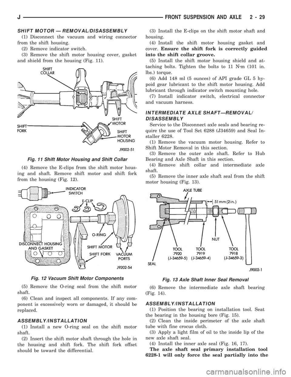
and shield from the housing (Fig. 11).
(4) Remove the E-clips from the shift motor hous-
ing and shaft. Remove shift motor and shift fork
from the housing (Fig. 12).
(5) Remove the O-ring seal from the shift motor
shaft.
(6) Clean and inspect all components. If any com-
ponent is excessively worn or damaged, it should be
replaced.
ASSEMBLY/INSTALLATION
(1) Install a new O-ring seal on the shift motor
shaft.
(2) Insert the shift motor shaft through the hole in
the housing and shift fork. The shift fork offset
should be toward the differential.(3) Install the E-clips on the shift motor shaft and
housing.
(4) Install the shift motor housing gasket and
cover.Ensure the shift fork is correctly guided
into the shift collar groove.
(5) Install the shift motor housing shield and at-
taching bolts. Tighten the bolts to 11 Nzm (101 in.
lbs.) torque.
(6) Add 148 ml (5 ounces) of API grade GL 5 hy-
poid gear lubricant to the shift motor housing. Add
lubricant through indicator switch mounting hole.
(7) Install indicator switch, electrical connector
and vacuum harness.
INTERMEDIATE AXLE SHAFTÐREMOVAL/
DISASSEMBLY
Service to the Disconnect axle seals and bearing re-
quire the use of Tool Set 6288 (J34659) and Seal In-
staller 6228.
(1) Remove the vacuum motor housing. Refer to
Shift Motor Removal in this section.
(3) Remove the outer axle shaft. Refer to Hub
Bearing and Axle Shaft in this section.
(4) Remove shift collar and intermediate axle
shaft.
(5) Remove the inner axle shaft seal from the shift
motor housing (Fig. 13).
(6) Remove the intermediate axle shaft bearing
(Fig. 14).
ASSEMBLY/INSTALLATION
(1) Position the bearing on installation tool. Seat
the bearing in the housing bore (Fig. 15).
(2) Clean the inside perimeter of the axle shaft
tube with fine crocus cloth.
(3) Apply a light film of oil to the inside lip of the
new axle shaft seal.
(4) Install the inner axle seal (Fig. 16, 17).
The axle shaft seal primary installation tool
6228-1 will only force the seal partially into the
Fig. 11 Shift Motor Housing and Shift Collar
Fig. 12 Vacuum Shift Motor ComponentsFig. 13 Axle Shaft Inner Seal Removal
JFRONT SUSPENSION AND AXLE 2 - 29
Page 69 of 1784
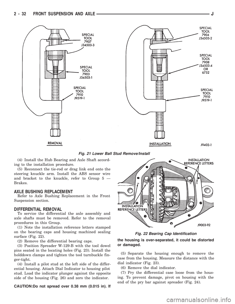
(4) Install the Hub Bearing and Axle Shaft accord-
ing to the installation procedure.
(5) Reconnect the tie-rod or drag link end onto the
steering knuckle arm. Install the ABS sensor wire
and bracket to the knuckle, refer to Group 5 Ð
Brakes.
AXLE BUSHING REPLACEMENT
Refer to Axle Bushing Replacement in the Front
Suspension section.
DIFFERENTIAL REMOVAL
To service the differential the axle assembly and
axle shafts must be removed. Refer to the removal
procedures in this Group.
(1) Note the installation reference letters stamped
on the bearing caps and housing machined sealing
surface (Fig. 22).
(2) Remove the differential bearing caps.
(3) Position Spreader W-129-B with the tool dowel
pins seated in the locating holes (Fig. 23). Install the
holddown clamps and tighten the tool turnbuckle fin-
ger-tight.
(4) Install a pilot stud at the left side of the differ-
ential housing. Attach Dial Indicator to housing pilot
stud. Load the indicator plunger against the opposite
side of the housing (Fig. 26) and zero the indicator.
CAUTION:Do not spread over 0.38 mm (0.015 in). Ifthe housing is over-separated, it could be distorted
or damaged.
(5) Separate the housing enough to remove the
case from the housing. Measure the distance with the
dial indicator (Fig. 23).
(6) Remove the dial indicator.
(7) Pry the differential case loose from the hous-
ing. To prevent damage, pivot on housing with the
end of the pry bar against spreader (Fig. 24).
Fig. 21 Lower Ball Stud Remove/Install
Fig. 22 Bearing Cap Identification
2 - 32 FRONT SUSPENSION AND AXLEJ
Page 77 of 1784
Arbor Discs have different steps to fit other
axle sizes. Pick correct size step for axle being
serviced.
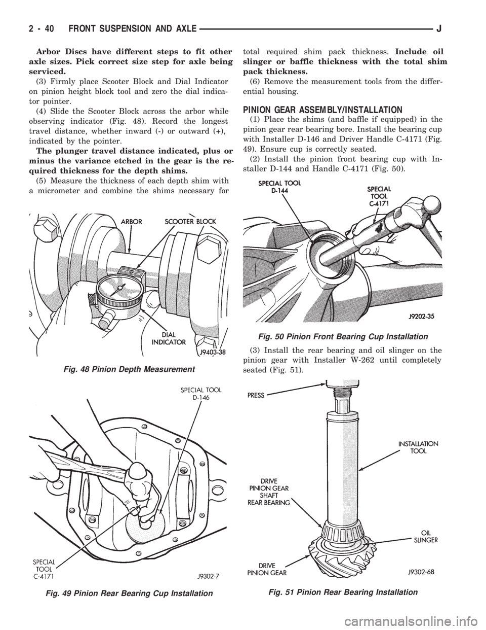
(3) Firmly place Scooter Block and Dial Indicator
on pinion height block tool and zero the dial indica-
tor pointer.
(4) Slide the Scooter Block across the arbor while
observing indicator (Fig. 48). Record the longest
travel distance, whether inward (-) or outward (+),
indicated by the pointer.
The plunger travel distance indicated, plus or
minus the variance etched in the gear is the re-
quired thickness for the depth shims.
(5) Measure the thickness of each depth shim with
a micrometer and combine the shims necessary fortotal required shim pack thickness.Include oil
slinger or baffle thickness with the total shim
pack thickness.
(6) Remove the measurement tools from the differ-
ential housing.
PINION GEAR ASSEMBLY/INSTALLATION
(1) Place the shims (and baffle if equipped) in the
pinion gear rear bearing bore. Install the bearing cup
with Installer D-146 and Driver Handle C-4171 (Fig.
49). Ensure cup is correctly seated.
(2) Install the pinion front bearing cup with In-
staller D-144 and Handle C-4171 (Fig. 50).
(3) Install the rear bearing and oil slinger on the
pinion gear with Installer W-262 until completely
seated (Fig. 51).
Fig. 48 Pinion Depth Measurement
Fig. 49 Pinion Rear Bearing Cup Installation
Fig. 50 Pinion Front Bearing Cup Installation
Fig. 51 Pinion Rear Bearing Installation
2 - 40 FRONT SUSPENSION AND AXLEJ
Page 111 of 1784
ing the IAC motor pintle in and out of the air control
passage. The IAC motor is positioned when the igni-
tion key is turned to the On position.
A (factory adjusted) set screw is used to mechani-
cally limit the position of the throttle body throttle
plate.Never attempt to adjust the engine idle
speed using this screw.All idle speed functions are
controlled by the PCM.
IGNITION COILÐPCM OUTPUT
System voltage is supplied to the ignition coil pos-
itive terminal. The powertrain control module (PCM)
operates the ignition coil.Base (initial) ignition
timing is not adjustable.The PCM adjusts ignition
timing to meet changing engine operating conditions.
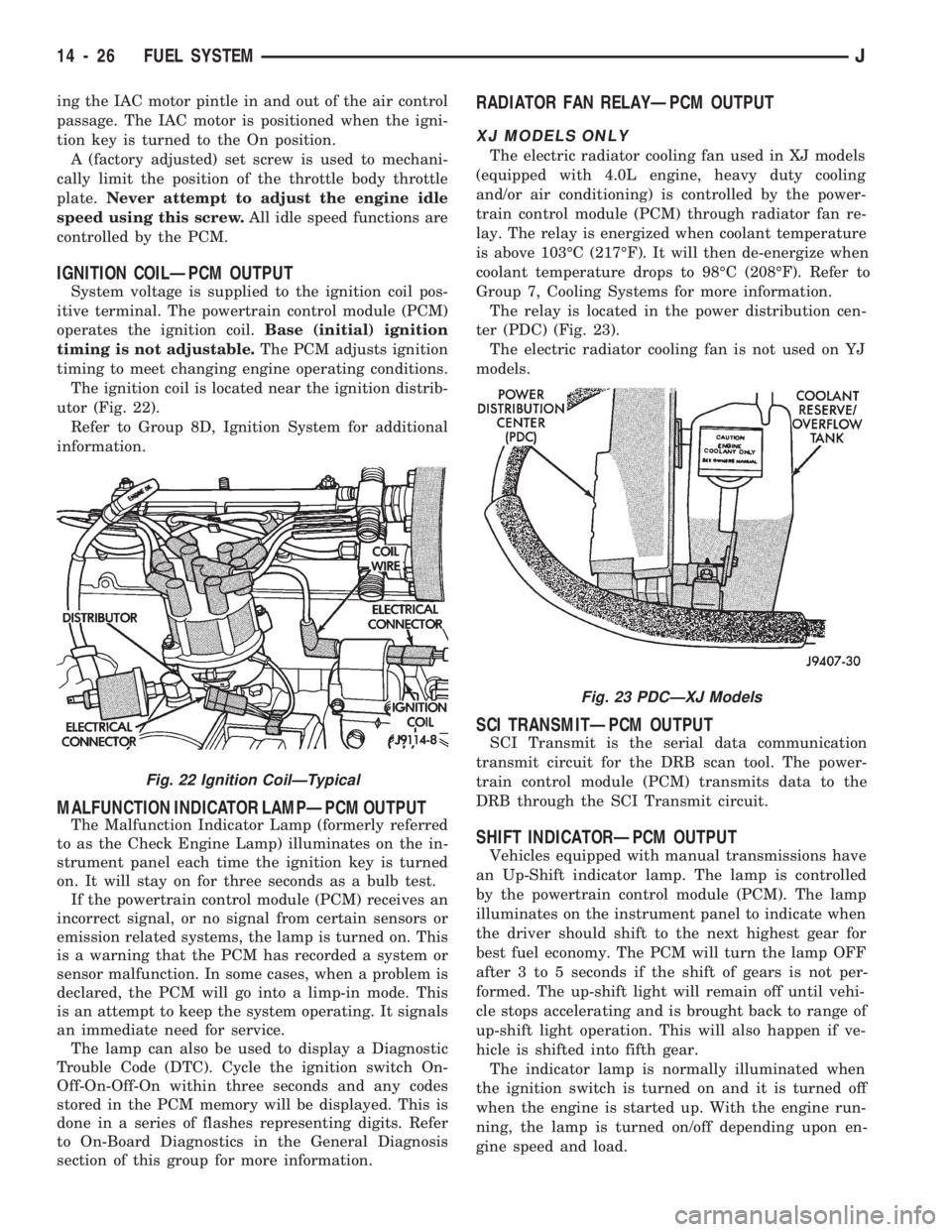
The ignition coil is located near the ignition distrib-
utor (Fig. 22).
Refer to Group 8D, Ignition System for additional
information.
MALFUNCTION INDICATOR LAMPÐPCM OUTPUT
The Malfunction Indicator Lamp (formerly referred
to as the Check Engine Lamp) illuminates on the in-
strument panel each time the ignition key is turned
on. It will stay on for three seconds as a bulb test.
If the powertrain control module (PCM) receives an
incorrect signal, or no signal from certain sensors or
emission related systems, the lamp is turned on. This
is a warning that the PCM has recorded a system or
sensor malfunction. In some cases, when a problem is
declared, the PCM will go into a limp-in mode. This
is an attempt to keep the system operating. It signals
an immediate need for service.
The lamp can also be used to display a Diagnostic
Trouble Code (DTC). Cycle the ignition switch On-
Off-On-Off-On within three seconds and any codes
stored in the PCM memory will be displayed. This is
done in a series of flashes representing digits. Refer
to On-Board Diagnostics in the General Diagnosis
section of this group for more information.
RADIATOR FAN RELAYÐPCM OUTPUT
XJ MODELS ONLY
The electric radiator cooling fan used in XJ models
(equipped with 4.0L engine, heavy duty cooling
and/or air conditioning) is controlled by the power-
train control module (PCM) through radiator fan re-
lay. The relay is energized when coolant temperature
is above 103ÉC (217ÉF). It will then de-energize when
coolant temperature drops to 98ÉC (208ÉF). Refer to
Group 7, Cooling Systems for more information.
The relay is located in the power distribution cen-
ter (PDC) (Fig. 23).
The electric radiator cooling fan is not used on YJ
models.
SCI TRANSMITÐPCM OUTPUT
SCI Transmit is the serial data communication
transmit circuit for the DRB scan tool. The power-
train control module (PCM) transmits data to the
DRB through the SCI Transmit circuit.
SHIFT INDICATORÐPCM OUTPUT
Vehicles equipped with manual transmissions have
an Up-Shift indicator lamp. The lamp is controlled
by the powertrain control module (PCM). The lamp
illuminates on the instrument panel to indicate when
the driver should shift to the next highest gear for
best fuel economy. The PCM will turn the lamp OFF
after 3 to 5 seconds if the shift of gears is not per-
formed. The up-shift light will remain off until vehi-
cle stops accelerating and is brought back to range of
up-shift light operation. This will also happen if ve-
hicle is shifted into fifth gear.
The indicator lamp is normally illuminated when
the ignition switch is turned on and it is turned off
when the engine is started up. With the engine run-
ning, the lamp is turned on/off depending upon en-
gine speed and load.
Fig. 23 PDCÐXJ Models
Fig. 22 Ignition CoilÐTypical
14 - 26 FUEL SYSTEMJ
Page 135 of 1784
Excessive Oil Consumption: Although the PCM
monitors exhaust stream oxygen content through ox-
ygen sensor (closed loop), it cannot determine exces-
sive oil consumption.
Throttle Body Air Flow: The PCM cannot detect
a clogged or restricted air cleaner inlet or air filter
element.
Evaporative System: The PCM will not detect a
restricted, plugged or loaded EVAP canister.
Vacuum Assist: Leaks or restrictions in the vac-
uum circuits of vacuum assisted engine control sys-
tem devices are not monitored by the PCM. However,
a vacuum leak at the MAP sensor will be monitored
and a diagnostic trouble code (DTC) will be gener-
ated by the PCM.
Powertrain Control Module (PCM) System
Ground: The PCM cannot determine a poor system
ground. However, a DTC may be generated as a re-
sult of this condition.
Powertrain Control Module (PCM) Connector
Engagement: The PCM cannot determine spread or
damaged connector pins. However, a DTC may be
generated as a result of this condition.
HIGH AND LOW LIMITS
The powertrain control module (PCM) compares in-
put signal voltages from each input device. It will es-
tablish high and low limits that are programmed into
it for that device. If the input voltage is not within
specifications and other Diagnostic Trouble Code
(DTC) criteria are met, a DTC will be stored in mem-
ory. Other DTC criteria might include engine rpm
limits or input voltages from other sensors or
switches. The other inputs might have to be sensed
by the PCM when it senses a high or low input volt-
age from the control system device in question.
ACCESSING DIAGNOSTIC TROUBLE CODES
A stored Diagnostic Trouble Code (DTC) can be dis-
played by cycling the ignition key On-Off-On-Off-On
within three seconds and observing the Malfunction
Indicator Lamp. This lamp was formerly referred to
as the Check Engine Lamp. The lamp is located on
the instrument panel.
They can also be displayed through the use of the
Diagnostic Readout Box (DRB) scan tool. The DRB
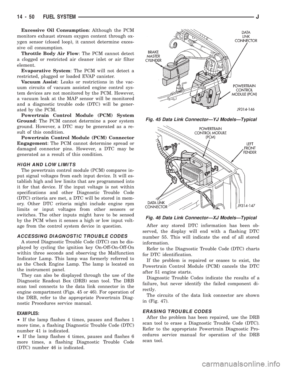
scan tool connects to the data link connector in the
engine compartment (Figs. 45 or 46). For operation of
the DRB, refer to the appropriate Powertrain Diag-
nostic Procedures service manual.
EXAMPLES:
²If the lamp flashes 4 times, pauses and flashes 1
more time, a flashing Diagnostic Trouble Code (DTC)
number 41 is indicated.
²If the lamp flashes 4 times, pauses and flashes 6
more times, a flashing Diagnostic Trouble Code
(DTC) number 46 is indicated.After any stored DTC information has been ob-
served, the display will end with a flashing DTC
number 55. This will indicate the end of all stored
information.
Refer to the Diagnostic Trouble Code (DTC) charts
for DTC identification.
If the problem is repaired or ceases to exist, the
Powertrain Control Module (PCM) cancels the DTC
after 51 engine starts.
Diagnostic Trouble Codes indicate the results of a
failure, but never identify the failed component di-
rectly.
The circuits of the data link connector are shown
in (Fig. 47).
ERASING TROUBLE CODES
After the problem has been repaired, use the DRB
scan tool to erase a Diagnostic Trouble Code (DTC).
Refer to the appropriate Powertrain Diagnostic Pro-
cedures service manual for operation of the DRB
scan tool.
Fig. 45 Data Link ConnectorÐYJ ModelsÐTypical
Fig. 46 Data Link ConnectorÐXJ ModelsÐTypical
14 - 50 FUEL SYSTEMJ