1994 JEEP CHEROKEE fuse box diagram
[x] Cancel search: fuse box diagramPage 495 of 1784

WIRE CODE IDENTIFICATION
Each wire shown in the diagrams contains a code
(Fig. 3) which identifies the main circuit, part of the
main circuit, gauge of wire, and color. The color is
shown as a two letter code which can be identified by
referring to the Wire Color Code Chart (Fig. 4). If the
wire has a tracer and it is a standard color an aster-
isk will follow the main wire color. If the tracer is
non-standard the main wire color will have a slash (/)
after it followed by the tracer color.
CIRCUIT IDENTIFICATION
All circuits in the diagrams use an alpha/numeric
code to identify the wire and its function. To identify
which circuit code applies to a system, refer to the
Circuit Identification Code Chart. This chart shows
the main circuits only and does not show the second-
ary codes that may apply to some models.
LOCATING A SYSTEM
To locate a system or component in the diagrams,
refer to the alphabetical index at the front of the di-
agrams. Determine the diagram sheet number. Sheet
numbers are located at the lower right or left handcorner of each sheet.Page numbers at the top of
the page do not apply to diagram sheets.
The index identifies the main system and all com-
ponents that relate to that system. There are also
sections of the index that identify specific compo-
nents only (for example modules, lamps, etc.). Refer
to a components name in the index if you are unclear
as to what a system may be called.
Diagram sheets are arranged starting with the bat-
tery and fuses. Then working into charging, starting,
and ignition systems. After this they start at the
front of the vehicle and work to rear. The diagrams
end with connector identification pages.
COMPONENT IDENTIFICATION
When looking for a components location in the vehicle
refer to the Component Identification section index.
This section shows the wire harness routing and the
components location in the vehicle. When using this sec-
tion refer to the wiring diagrams for the general loca-
tion of the component. Then use the component
identification index to locate the proper figure number.
SPLICE LOCATIONS
Splice locations are indicated in the diagrams by a
diamond with a splice circuit code within it (Fig. 5
example 1). If there is more than one splice per cir-
cuit a small box will be connected to it with the
splice number in it (Fig. 5 example 2).
To locate a splice in the wiring harness determine
the splice number from the wiring diagrams then re-
fer to the splice location index. This section shows
the general location of the splice in the harness.
Fig. 2 Secondary Ignition Wiring 4.0L
Fig. 3 Wire Color Code Identification
Fig. 4 Wire Color Code Chart
8W - 2 WIRING DIAGRAMSJ
Page 496 of 1784

CONNECTORS
The connectors shown in the diagram sheets are
viewed from the terminal end unless otherwise speci-
fied. For viewing bulkhead, powertrain control module,
and transmission control module connectors refer to the
rear of the wiring diagrams. This area shows major con-
nectors and identifies pin and cavity information.
The connectors shown in the diagrams are identi-
fied in two ways. The first is an actual view of the
connector. This view shows the connector and which
cavity the wire is in.
The second way is with the use of arrows to indicate
the connector. This is done when the connector is to
large to be shown on the diagram page. A box placed
next to the connector identifies the connector and the
cavity the wire is in. In certain instances there may be
more than one connector in the same location. When
this happens the connector identification box will have a
number placed in it. Refer to the rear of the diagrams
for a complete pin out of the connector.
TROUBLESHOOTING WIRING PROBLEMS
When troubleshooting wiring problems there are
six steps which can aid in the procedure. The steps
are listed and explained below.(1) Verify the problem.
(2) Verify any related symptoms. Do this by per-
forming operational checks on components that are
in the same circuit as the problem area. Refer to the
wiring diagrams fuse application chart for circuit
identification.
(3) Analyze the symptoms. Use the wiring dia-
grams to determine what the circuit is doing, where
the problem most likely is occurring and where the
diagnosis will continue.
(4) Isolate the problem area.
(5) Repair the problem.
(6) Verify proper operation. For this step check for
proper operation of all items on the circuit repaired.
Refer to the wiring diagram fuse application chart for
circuit identification.
FUSIBLE LINKS
Vehicle wiring harnesses are equipped with fusible
links to protect against harness damage in the event
of a short in the system. Fusible links are color coded
to indicate wire gauge and size. Refer to the fusible
link chart for color and gauge identification (Fig. 6).
Fig. 5 Wiring Splice Examples
Fig. 6 Fusible Link Chart
JWIRING DIAGRAMS 8W - 3
Page 644 of 1784

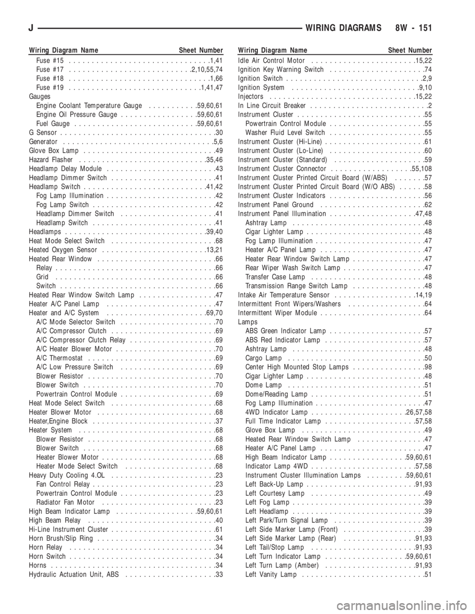
Wiring Diagram Name Sheet Number
Fuse #15...............................1,41
Fuse #17...........................2,10,55,74
Fuse #18...............................1,66
Fuse #19.............................1,41,47
Gauges
Engine Coolant Temperature Gauge...........59,60,61
Engine Oil Pressure Gauge.................59,60,61
Fuel Gauge...........................59,60,61
G Sensor..................................30
Generator.................................5,6
Glove Box Lamp.............................49
Hazard Flasher............................35,46
Headlamp Delay Module........................43
Headlamp Dimmer Switch.......................41
Headlamp Switch...........................41,42
Fog Lamp Illumination........................42
Fog Lamp Switch...........................42
Headlamp Dimmer Switch.....................41
Headlamp Switch...........................41
Headlamps...............................39,40
Heat Mode Select Switch.......................68
Heated Oxygen Sensor.......................13,21
Heated Rear Window..........................66
Relay...................................66
Grid...................................66
Switch..................................66
Heated Rear Window Switch Lamp.................47
Heater A/C Panel Lamp........................47
Heater and A/C System......................69,70
A/C Mode Selector Switch.....................70
A/C Compressor Clutch.......................69
A/C Compressor Clutch Relay...................69
A/C Heater Blower Motor......................70
A/C Thermostat............................69
A/C Low Pressure Switch.....................69
Blower Resistor............................70
Blower Switch.............................70
Powertrain Control Module.....................69
Heat Mode Select Switch.......................68
Heater Blower Motor..........................68
Heater,Engine Block...........................37
Heater System..............................68
Blower Resistor............................68
Blower Switch.............................68
Heater Blower Motor.........................68
Heater Mode Select Switch....................68
Heavy Duty Cooling 4.OL.......................23
Fan Control Relay...........................23
Powertrain Control Module.....................23
Radiator Fan Motor.........................23
High Beam Indicator Lamp..................59,60,61
High Beam Relay............................40
Hi-Line Instrument Cluster.......................61
Horn Brush/Slip Ring..........................34
Horn Relay................................34
Horn Switch................................34
Horns....................................34
Hydraulic Actuation Unit, ABS....................33Wiring Diagram Name Sheet Number
Idle Air Control Motor.......................15,22
Ignition Key Warning Switch.....................74
Ignition Switch..............................2,9
Ignition System............................9,10
Injectors................................15,22
In Line Circuit Breaker..........................2
Instrument Cluster............................55
Powertrain Control Module.....................55
Washer Fluid Level Switch.....................55
Instrument Cluster (Hi-Line)......................61
Instrument Cluster (Lo-Line).....................60
Instrument Cluster (Standard)....................59
Instrument Cluster Connector..................55,108
Instrument Cluster Printed Circuit Board (W/ABS).......57
Instrument Cluster Printed Circuit Board (W/O ABS)......58
Instrument Cluster Indicators.....................56
Instrument Panel Ground.......................62
Instrument Panel Illumination...................47,48
Ashtray Lamp.............................48
Cigar Lighter Lamp..........................48
Fog Lamp Illumination........................47
Heater A/C Panel Lamp.......................47
Heater Rear Window Switch Lamp................47
Rear Wiper Wash Switch Lamp..................47
Transfer Case Lamp.........................48
Transmission Range Switch Lamp................48
Intake Air Temperature Sensor..................14,19
Intermittent Front Wipers/Washers.................64
Intermittent Wiper Module.......................64
Lamps
ABS Green Indicator Lamp.....................57
ABS Red Indicator Lamp......................57
Ashtray Lamp.............................48
Cargo Lamp..............................50
Center High Mounted Stop Lamps................98
Cigar Lighter Lamp..........................48
Dome Lamp..............................51
Dome/Reading Lamp.........................51
Fog Lamp Illumination........................47
4WD Indicator Lamp.....................26,57,58
Full Time Indicator Lamp....................57,58
Glove Box Lamp...........................49
Heated Rear Window Switch Lamp...............47
Heater A/C Panel Lamp.......................47
High Beam Indicator Lamp.................59,60,61
Indicator Lamp 4WD.......................57,58
Instrument Cluster Illumination Lamps.........59,60,61
Left Back-Up Lamp........................91,93
Left Courtesy Lamp.........................49
Left Fog Lamp.............................39
Left Headlamp.............................39
Left Park/Turn Signal Lamp....................39
Left Side Marker Lamp (Front)..................39
Left Side Marker Lamp (Rear)................91,93
Left Tail/Stop Lamp.......................91,93
Left Turn Indicator Lamp..................59,60,61
Left Turn Lamp (Amber)....................91,93
Left Vanity Lamp...........................51
JWIRING DIAGRAMS 8W - 151
Page 765 of 1784

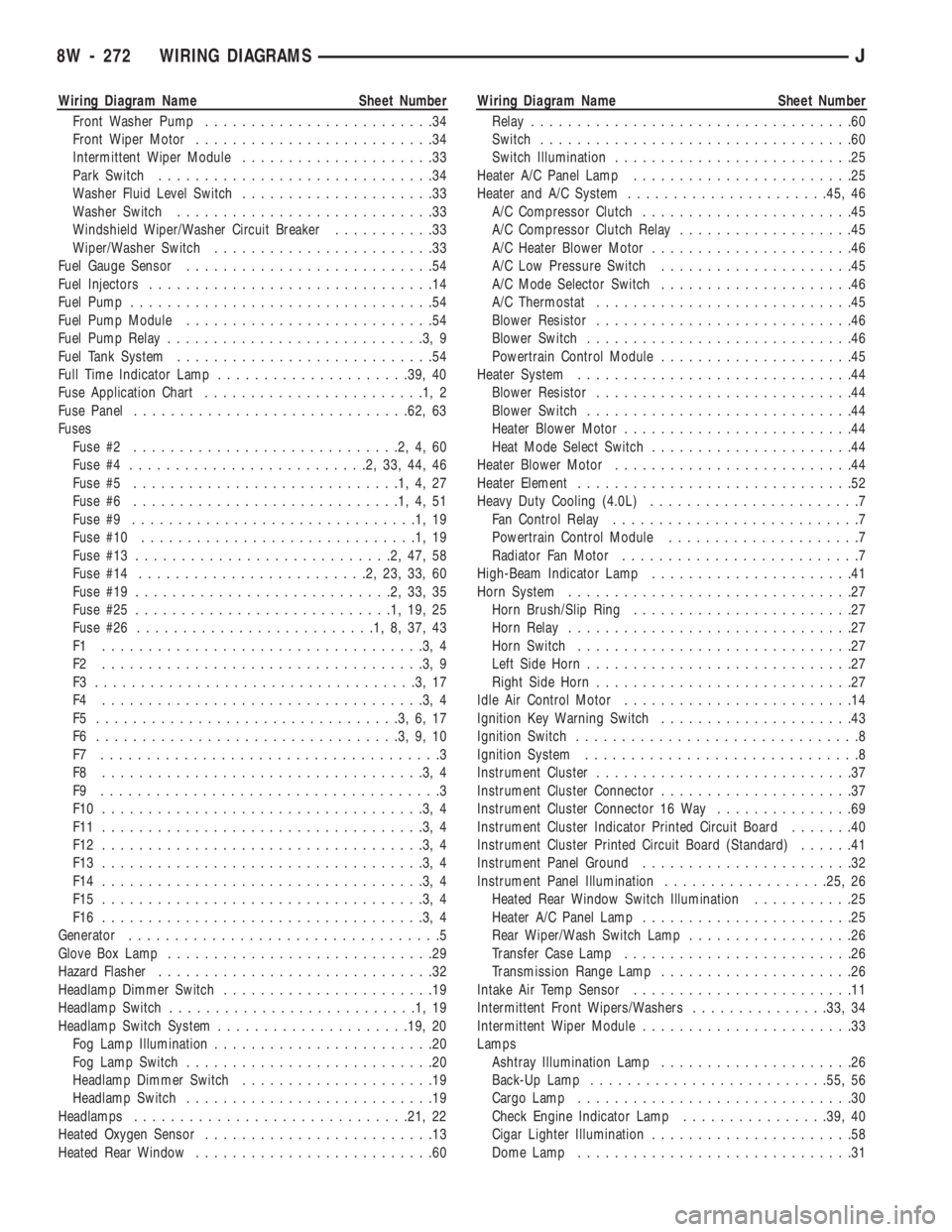
Wiring Diagram Name Sheet Number
Front Washer Pump.........................34
Front Wiper Motor..........................34
Intermittent Wiper Module.....................33
Park Switch..............................34
Washer Fluid Level Switch.....................33
Washer Switch............................33
Windshield Wiper/Washer Circuit Breaker...........33
Wiper/Washer Switch........................33
Fuel Gauge Sensor...........................54
Fuel Injectors...............................14
Fuel Pump.................................54
Fuel Pump Module...........................54
Fuel Pump Relay............................3,9
Fuel Tank System............................54
Full Time Indicator Lamp.....................39, 40
Fuse Application Chart........................1,2
Fuse Panel..............................62, 63
Fuses
Fuse #2.............................2,4,60
Fuse #4..........................2,33,44,46
Fuse #5.............................1,4,27
Fuse #6.............................1,4,51
Fuse #9...............................1,19
Fuse #10..............................1,19
Fuse #13............................2,47,58
Fuse #14.........................2,23,33,60
Fuse #19............................2,33,35
Fuse #25............................1,19,25
Fuse #26..........................1,8,37,43
F1 ...................................3,4
F2 ...................................3,9
F3 ...................................3,17
F4 ...................................3,4
F5 .................................3,6,17
F6 .................................3,9,10
F7 .....................................3
F8 ...................................3,4
F9 .....................................3
F10 ...................................3,4
F11 ...................................3,4
F12 ...................................3,4
F13 ...................................3,4
F14 ...................................3,4
F15 ...................................3,4
F16 ...................................3,4
Generator..................................5
Glove Box Lamp.............................29
Hazard Flasher..............................32
Headlamp Dimmer Switch.......................19
Headlamp Switch...........................1,19
Headlamp Switch System.....................19, 20
Fog Lamp Illumination........................20
Fog Lamp Switch...........................20
Headlamp Dimmer Switch.....................19
Headlamp Switch...........................19
Headlamps..............................21, 22
Heated Oxygen Sensor.........................13
Heated Rear Window..........................60Wiring Diagram Name Sheet Number
Relay...................................60
Switch..................................60
Switch Illumination..........................25
Heater A/C Panel Lamp........................25
Heater and A/C System......................45, 46
A/C Compressor Clutch.......................45
A/C Compressor Clutch Relay...................45
A/C Heater Blower Motor......................46
A/C Low Pressure Switch.....................45
A/C Mode Selector Switch.....................46
A/C Thermostat............................45
Blower Resistor............................46
Blower Switch.............................46
Powertrain Control Module.....................45
Heater System..............................44
Blower Resistor............................44
Blower Switch.............................44
Heater Blower Motor.........................44
Heat Mode Select Switch......................44
Heater Blower Motor..........................44
Heater Element..............................52
Heavy Duty Cooling (4.0L).......................7
Fan Control Relay...........................7
Powertrain Control Module.....................7
Radiator Fan Motor..........................7
High-Beam Indicator Lamp......................41
Horn System...............................27
Horn Brush/Slip Ring........................27
Horn Relay...............................27
Horn Switch..............................27
Left Side Horn.............................27
Right Side Horn............................27
Idle Air Control Motor.........................14
Ignition Key Warning Switch.....................43
Ignition Switch...............................8
Ignition System..............................8
Instrument Cluster............................37
Instrument Cluster Connector.....................37
Instrument Cluster Connector 16 Way...............69
Instrument Cluster Indicator Printed Circuit Board.......40
Instrument Cluster Printed Circuit Board (Standard)......41
Instrument Panel Ground.......................32
Instrument Panel Illumination..................25, 26
Heated Rear Window Switch Illumination...........25
Heater A/C Panel Lamp.......................25
Rear Wiper/Wash Switch Lamp..................26
Transfer Case Lamp.........................26
Transmission Range Lamp.....................26
Intake Air Temp Sensor........................11
Intermittent Front Wipers/Washers...............33, 34
Intermittent Wiper Module.......................33
Lamps
Ashtray Illumination Lamp.....................26
Back-Up Lamp..........................55, 56
Cargo Lamp..............................30
Check Engine Indicator Lamp................39, 40
Cigar Lighter Illumination......................58
Dome Lamp..............................31
8W - 272 WIRING DIAGRAMSJ
Page 1754 of 1784

FUSES AND ABBREVIATIONS, SYMBOLS, . . . 8W-6
FUSIBLE LINK REPLACEMENT............8W-4
FUSIBLE LINKS........................8W-3
GALVANIZED METALS, PAINT REPAIR ON . . 23-202
GAP ADJUSTMENT, WHEEL SENSOR AIR....5-49
GAP, REAR SPEED SENSOR AIR............5-3
GASKET FAILURE DIAGNOSIS, ENGINE
CYLINDER HEAD.......................9-5
GASKETS, FORM-IN-PLACE................9-1
GAUGE AND MANIFOLD ASSEMBLY,
PRESSURE..........................24-2
GAUGE CALIBRATION VALUES............8E-22
GAUGE CLUSTER REPLACEMENT.........8E-24
GAUGE, COOLANT TEMPERATURE..........8E-1
GAUGE, FUEL..........................8E-2
GAUGE HOUSINGS, INSTRUMENT
CLUSTER..........................23-190
GAUGE INOPERATIVE, COOLANT
TEMPERATURE.......................8E-3
GAUGE INOPERATIVE, FUEL...............8E-3
GAUGE INOPERATIVE, OIL PRESSURE......8E-3
GAUGE INOPERATIVE, ONE..............8E-22
GAUGE, OIL PRESSURE..................8E-1
GAUGE PACKAGE DIAGNOSIS............8E-22
GAUGE PACKAGE GAUGE REPLACEMENT . . . 8E-24
GAUGE PACKAGE GENERAL
INFORMATION.......................8E-22
GAUGE PACKAGE SERVICE PROCEDURES . . . 8E-24
GAUGE REPLACEMENT, GAUGE
PACKAGE...........................8E-24
GAUGE REPLACEMENTÐINSTRUMENT
CLUSTER REMOVED...................8E-5
GAUGE SENDING UNIT, FUEL.............14-15
GAUGES AND INDICATORS INOPERATIVE....8E-3
GAUGES INOPERATIVE (FIG. 15), ALL......8E-22
GAUGES, INSTRUMENT CLUSTER;
INSTRUMENT PANEL AND GAUGESÐ
XJ ................................8E-13
GAUGES, INSTRUMENT CLUSTER;
INSTRUMENT PANEL AND GAUGESÐ
YJ ................................8E-27
GAUGES, INSTRUMENT PANEL......8A-1 ,8E-27
GAUGES, PRESSURE....................22-2
GAUGESÐXJ, INSTRUMENT PANEL........8E-1
GAUGESÐYJ, INSTRUMENT PANEL........8E-1
GEAR (1) POSITION, HYDRAULIC FLOW
IN MANUAL FIRST...................21-94
GEAR ADJUSTMENTS IN VEHICLE.........19-37
GEAR ADJUSTMENTS ON BENCH.........19-42
GEAR ADJUSTMENTS, STEERING.........19-22
GEAR AND BEARING NOISE; FRONT
SUSPENSION AND AXLE................2-16
GEAR AND BEARING NOISE; REAR
SUSPENSION AND AXLES................3-7
GEAR AND CLUTCH OVERHAUL,
OVERDRIVE PLANETARY..............21-209
GEAR AND NO. 1 ONE-WAY CLUTCH
OVERHAUL, SUN....................21-229
GEAR ASSEMBLY, STEERING.............19-41
GEAR ASSEMBLY/INSTALLATION,
PINION; FRONT SUSPENSION AND AXLE....2-40
GEAR ASSEMBLY/INSTALLATION,
PINION; REAR SUSPENSION AND AXLES....3-22
GEAR CLEANING AND INSPECTION........19-40
GEAR COMPONENTS, FIRSTÐTHIRDÐ
REVERSE..........................21-159
GEAR (CONVERTER CLUTCH
ENGAGED), HYDRAULIC FLOW IN
THIRD.............................21-90
GEAR DEPTH INFORMATION, PINION;
FRONT SUSPENSION AND AXLE..........2-37
GEAR DEPTH INFORMATION, PINION;
REAR SUSPENSION AND AXLES..........3-19
GEAR DEPTH VARIANCE, PINION; FRONT
SUSPENSION AND AXLE................2-38
GEAR DEPTH VARIANCE, PINION; REAR
SUSPENSION AND AXLES...........3-20,3-38
GEAR DISASSEMBLY INFORMATION.......19-24
GEAR, HYDRAULIC FLOW IN D RANGE
FIRST..............................21-87
GEAR, HYDRAULIC FLOW IN D RANGE
SECOND
............................21-88
GEAR, HYDRAULIC FLOW IN D
RANGE THIRD
.......................21-89
GEAR INSTALLATION, RING
...............3-24
GEAR LEAKAGE DIAGNOSIS
..............19-8GEAR, MANUAL STEERING.........19-35,19-73
GEAR OVERDRIVE COMPONENTS,
FOURTH...........................21-158
GEAR OVERHAUL, FRONT PLANETARY....21-228
GEAR OVERHAUL, GOVERNOR AND
PARK .............................21-121
GEAR, POWER STEERING...............19-73
GEAR RATIOS..........................21-2
GEAR RATIOS, TRANSMISSION...........21-33
GEAR, RECIRCULATING BALL POWER
STEERING..........................19-19
GEAR REPLACEMENT, STEERING....19-21,19-43
GEAR SELECTOR INDICATOR
REPLACEMENTÐINSTRUMENT
CLUSTER REMOVED...................8E-6
GEAR SERVICE, GOVERNOR AND PARK . . . 21-101
GEAR SPECIFICATIONS, MANUAL
STEERING..........................19-44
GEAR SPECIFICATIONS, POWER
STEERING..........................19-34
GEAR, SPEED SENSOR ROTORÐ
SPEEDOMETER DRIVE...............21-183
GEAR TRAIN OVERHAUL, PLANETARY.....21-131
GEARÐYJ VEHICLES, MANUAL
STEERING...........................0-32
GEARS, RECIRCULATING-BALL
POWER STEERING...................19-69
GEARSHIFT LINKAGE...................21-70
GEARSHIFT LINKAGE ADJUSTMENT (YJ) . . . 21-96
GEARTRAIN OPERATION AND
APPLICATION CHARTS...............21-159
GENERAL; BATTERY/STARTER/
GENERATOR SERVICE..................8B-7
GENERAL BODY SERVICE INFORMATION....23-1
GENERAL; CHIME/BUZZER WARNING
SYSTEMS...........................8U-1
GENERAL DIAGNOSIS INFORMATION;
CLUTCH..............................6-3
GENERAL DIAGNOSIS INFORMATION;
TRANSMISSION AND TRANSFER
CASE.............................21-167
GENERAL; HEATING AND AIR
CONDITIONING.......................24-8
GENERAL INFORMATION, 2.5L STARTER....8B-4
GENERAL INFORMATION, 4.0L STARTER....8B-6
GENERAL INFORMATION; AUDIO
SYSTEMS........................8F-1,8F-8
GENERAL INFORMATION, BATTERY
TESTING............................8A-3
GENERAL INFORMATION; BATTERY/
STARTER/GENERATOR SERVICE......8B-1,8B-4
GENERAL INFORMATION; BRAKES . . . 5-1,5-7,5-24,
5-39,5-65
GENERAL INFORMATION; CLUTCH..........6-1
GENERAL INFORMATION; COOLING
SYSTEM.................7-1,7-31,7-37,7-38
GENERAL INFORMATION; ELECTRICAL . 8A-1,8A-2,
8A-8,8A-9,8A-14
GENERAL INFORMATION; EMISSION
CONTROL SYSTEMS...................25-1
GENERAL INFORMATION; ENGINES......9-9,9-50
GENERAL INFORMATION; EXHAUST
SYSTEM AND INTAKE MANIFOLD.........11-1
GENERAL INFORMATION; FRAME AND
BUMPERS.......................13-1,13-8
GENERAL INFORMATION; FRONT
SUSPENSION AND AXLE..........2-1,2-5,2-16
GENERAL INFORMATION, FRONT WIPERS/
WASHERS...........................8K-8
GENERAL INFORMATION; FUEL SYSTEM....14-1,
14-12,14-16,14-17,14-32,14-62
GENERAL INFORMATION, GAUGE
PACKAGE...........................8E-22
GENERAL INFORMATION; HEATING
AND AIR CONDITIONING................24-1
GENERAL INFORMATION; HORNS..........8G-1
GENERAL INFORMATION; IGNITION
SYSTEMS
.......8D-1,8D-8,8D-20,8D-30,8D-33
GENERAL INFORMATION, INSTRUMENT
CLUSTER; INSTRUMENT PANEL
AND GAUGESÐXJ
....................8E-1
GENERAL INFORMATION, INSTRUMENT
CLUSTER; INSTRUMENT PANEL AND
GAUGESÐYJ
........................8E-14
GENERAL INFORMATION; LUBRICATION
AND MAINTENANCE
....................0-1GENERAL INFORMATION; PROPELLER
SHAFTS.............................16-1
GENERAL INFORMATION; REAR
SUSPENSION AND AXLES........3-1,3-7,3-11
GENERAL INFORMATION; STEERING........19-1
GENERAL INFORMATION; TRANSMISSION
AND TRANSFER CASE.......21-1,21-32,21-66,
21-69,21-156,21-272,21-293
GENERAL INFORMATION; VEHICLE
SPEED CONTROL SYSTEM..............8H-1
GENERAL INFORMATION; WHEELS AND
TIRES..........................22-1,22-6
GENERAL INFORMATION; WIRING
DIAGRAMS..........................8W-1
GENERAL; POWER DOOR LOCKS..........8P-1
GENERAL; POWER MIRRORS.............8T-1
GENERAL; POWER SEATS................8R-1
GENERAL; REAR WINDOW DEFOGGER......8N-1
GENERAL SERVICE INFORMATION; BODY
COMPONENTSÐXJ VEHICLES.........23-132
GENERAL SERVICE INFORMATION;
BRAKES.........................5-20,5-56
GENERAL SERVICE MAINTENANCE..........0-5
GENERAL SERVICE PROCEDURE
INFORMATION.......................19-69
GENERAL SERVICE, STEERING COLUMN . . . 19-45
GENERAL SPECIFICATIONS, 30RH/32RH . . . 21-322
GENERAL SPECIFICATIONS, AW-4........21-324
GENERATOR DIAGNOSTIC TROUBLE
CODE (DTC)........................8A-19
GENERATOR FIELDÐPCM OUTPUT........14-25
GENERATOR LAMPÐPCM OUTPUT........14-25
GENERATOR REPLACEMENTÐLEFT
HAND DRIVE.........................8B-7
GENERATOR REPLACEMENTÐ
RIGHT HAND DRIVE...................8B-9
GENERATOR SERVICE PROCEDURES.......8B-7
GENERATOR SPECIFICATIONS............8B-12
GENERATOR SPLASH SHIELD............13-14
GENERATOR TEST PROCEDURES ON
VEHICLE...........................8A-14
GLASS AND DOOR OPENING WEATHERSTRIP
SEALS, DOOR WINDOW...............23-62
GLASS, FIXEDÐWATER LEAK
DETECTION AND REPAIR........23-83,23-189
GLASS, FIXED WINDOW..........23-73,23-183
GLASS, FRONT DOOR WINDOW..........23-49
GLASS, FULL-METAL DOOR VENT
WINDOW..........................23-177
GLASS, FULL-METAL DOOR WINDOW.....23-178
GLASS, HARD TOP LIFTGATE............23-162
GLASS, HARD TOP QUARTER WINDOW . . . 23-188
GLASS, REAR DOOR FIXED WINDOW......23-53
GLASS, REAR DOOR WINDOW
...........23-52
GLASS REGULATOR, FRONT DOOR
WINDOW
...........................23-48
GLASS REGULATOR, FULL-METAL
DOOR WINDOW
....................23-177
GLASS REGULATOR HANDLE, FULL-
METAL DOOR WINDOW
..............23-175
GLASS REGULATOR, REAR DOOR
WINDOW
...........................23-51
GLASS REPLACEMENT, WINDSHIELD
......23-75
GLASS, SIGHT
........................24-41
GLASS WEATHERSTRIP SEAL
REPLACEMENT, LIFTGATE
.............23-163
GLASS, WINDSHIELD
..................23-185
GLASSÐXJ VEHICLES, LIFTGATE
WINDOW
...........................23-81
GLASSÐXJ VEHICLES, REAR
QUARTER VENT WINDOW
..............23-80
GLASS/REAR QUARTER PLASTIC INSERT
ÐXJ VEHICLES, QUARTER WINDOW
.....23-80
GLOVE BOX
.........................23-194
GOVERNOR AND PARK GEAR
OVERHAUL
........................21-121
GOVERNOR AND PARK GEAR SERVICE
....21-101
GRID REPAIR, REAR WINDOW
DEFOGGER
..........................8N-2
GRID TEST, REAR WINDOW DEFOGGER
.....8N-1
GRILLE AND GRILLE OPENING PANEL
(GOP)
..............................23-3
GRILLE AND SCREEN, COWL
.......23-11,23-139
GRILLE APPLIQUE, RADIATOR
...........23-134
10 INDEXJ
Description Group-Page Description Group-Page Description Group-Page