1994 JEEP CHEROKEE warning
[x] Cancel search: warningPage 8 of 1784
JUMP STARTING, HOISTING AND TOWING
JUMP STARTING
WARNING: DO NOT ATTEMPT TO PUSH OR TOW A
VEHICLE TO START THE ENGINE. UNBURNED
FUEL COULD ENTER THE EXHAUST CATALYTIC
CONVERTER AND IGNITE AFTER THE ENGINE IS
STARTED. THIS COULD CAUSE THE CONVERTER
TO OVERHEAT AND RUPTURE.
BOOSTER BATTERY
WARNING: TO PREVENT PERSONAL INJURY OR
CLOTHING DAMAGE, DO NOT ALLOW BATTERY
(ACID) TO CONTACT EYES, SKIN OR CLOTHING.
DO NOT LEAN OVER A BATTERY WHEN CON-
NECTING JUMPER CABLES. DO NOT ALLOW THE
POSITIVE AND NEGATIVE CABLE CONNECTOR
CLAMPS TO CONTACT EACH OTHER. KEEP OPEN
FLAMES AND SPARKS AWAY FROM THE BATTERY
VENT HOLES. ALWAYS WEAR EYE PROTECTION
WHEN INVOLVED WITH BATTERIES.
If it is necessary to use a booster battery and
jumper cables to start an engine use the following
procedure.
(1) Engage the parking brake and shift the auto-
matic transmission to PARK, manual transmission
shift to NEUTRAL.
(2) Turn off all lights, the heater-A/C blower mo-
tor, and all other electrical loads.
WARNING: WHEN THE AIR TEMPERATURE IS BE-
LOW THE FREEZING POINT (0ÉC OR 32ÉF), THE
ACID IN A DISCHARGED VEHICLE BATTERY CAN
FREEZE. DO NOT ATTEMPT TO JUMP START AN
ENGINE BEFORE DETERMINING THE CONDITION
OF THE BATTERY.
(3) Inspect the general condition of the battery.
CAUTION: Do not permit metal surfaces on vehicles
to contact because this could establish ground con-
tinuity between vehicle bodies.
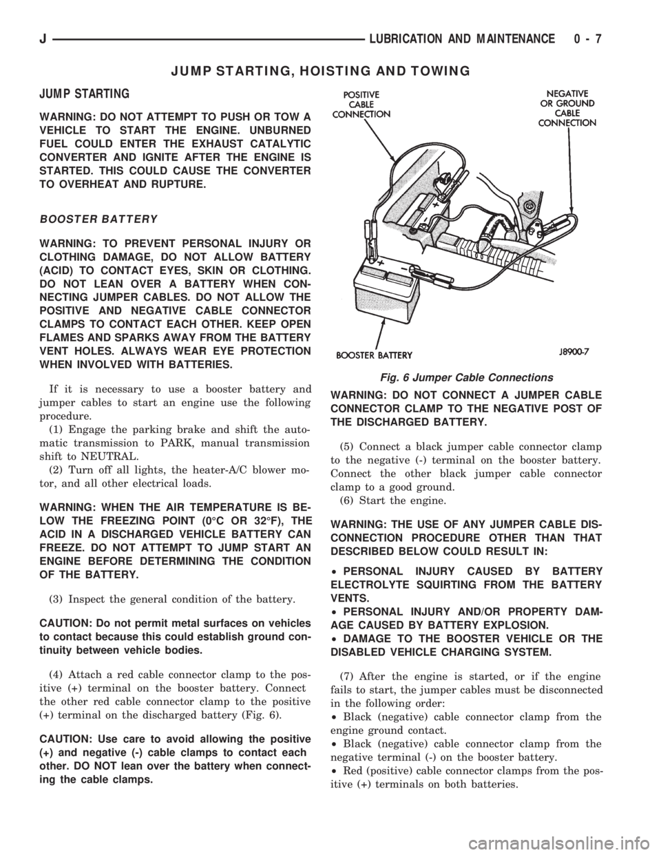
(4) Attach a red cable connector clamp to the pos-
itive (+) terminal on the booster battery. Connect
the other red cable connector clamp to the positive
(+) terminal on the discharged battery (Fig. 6).
CAUTION: Use care to avoid allowing the positive
(+) and negative (-) cable clamps to contact each
other. DO NOT lean over the battery when connect-
ing the cable clamps.WARNING: DO NOT CONNECT A JUMPER CABLE
CONNECTOR CLAMP TO THE NEGATIVE POST OF
THE DISCHARGED BATTERY.
(5) Connect a black jumper cable connector clamp
to the negative (-) terminal on the booster battery.
Connect the other black jumper cable connector
clamp to a good ground.
(6) Start the engine.
WARNING: THE USE OF ANY JUMPER CABLE DIS-
CONNECTION PROCEDURE OTHER THAN THAT
DESCRIBED BELOW COULD RESULT IN:
²PERSONAL INJURY CAUSED BY BATTERY
ELECTROLYTE SQUIRTING FROM THE BATTERY
VENTS.
²PERSONAL INJURY AND/OR PROPERTY DAM-
AGE CAUSED BY BATTERY EXPLOSION.
²DAMAGE TO THE BOOSTER VEHICLE OR THE
DISABLED VEHICLE CHARGING SYSTEM.
(7) After the engine is started, or if the engine
fails to start, the jumper cables must be disconnected
in the following order:
²Black (negative) cable connector clamp from the
engine ground contact.
²Black (negative) cable connector clamp from the
negative terminal (-) on the booster battery.
²Red (positive) cable connector clamps from the pos-
itive (+) terminals on both batteries.
Fig. 6 Jumper Cable Connections
JLUBRICATION AND MAINTENANCE 0 - 7
Page 10 of 1784
²if the vehicle is damaged, secure the loose and pro-
truding parts;
²always use a safety chain system that is indepen-
dent of the lifting and towing equipment;
²do not allow any of the towing equipment to con-
tact the disabled vehicle's fuel tank;
²do not allow anyone to be under the disabled vehi-
cle while it is lifted by the towing equipment;
²do not allow passengers to ride in a vehicle being
towed;
²always observe all state and local laws involving
warning signals, night illumination, speed, etc.
²do not attempt a towing operation that could jeop-
ardize the safety of the operator, bystanders or other
motorists;
²do not exceed a towing speed of 48 km/h (30 mph);
²avoid towing distances of more than 24 km (15
miles) whenever possible; and
²do not attach tow chains or a tow sling to a
bumper, the steering linkage, the universal joints,
the constant velocity (CV) joints, or a drive shaft.
CLEARANCES AND RAMP ANGLE
SURFACE CLEARANCE
The end of the disabled vehicle that is attached to
the tow vehicle should be lifted a minimum of 10 cm
or four inches off the surface. Inspect to ensure that
the opposite end of the disabled vehicle has clearance
from the surface.
RAMP ANGLEÐFLAT-BED TOWING
If a vehicle with flat-bed towing equipment is used,
the approach ramp angle should not exceed 15 de-
grees.
SLING-TYPE, FRONT-END TOWING
XJ VEHICLES
Use the following guidelines when the tow vehicle
is attached to the front end of a disabled vehicle.
(1) Always tow with the front wheels lifted off the
surface and turned all the way to the right.
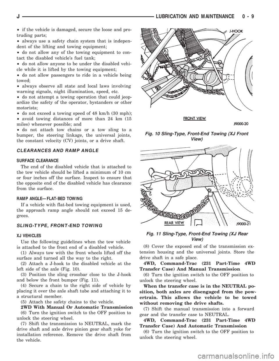
(2) Attach a J-hook to the disabled vehicle at the
left side of the axle (Fig. 10).
(3) Position the sling crossbar close to the J-hook
and below the front bumper (Fig. 11).
(4) Secure a chain to the right side of vehicle by
placing it over the axle shaft tube and attaching it to
a structural member.
(5) Attach the safety chains to the vehicle.
2WD With Manual Or Automatic Transmission
(6) Turn the ignition switch to the OFF position to
unlock the steering wheel.
(7) Shift the transmission to NEUTRAL, mark the
drive shaft and axle drive pinion gear shaft yoke for
installation reference. Remove the drive shaft from
the vehicle.(8) Cover the exposed end of the transmission ex-
tension housing and the universal joints. Store the
drive shaft in a safe place.
4WD, Command-Trac (231 Part-Time 4WD
Transfer Case) And Manual Transmission
(6) Turn the ignition switch to the OFF position to
unlock the steering wheel.
When the transfer case is in the NEUTRAL po-
sition, both axles are disengaged from the pow-
ertrain. This allows the vehicle to be towed
without removing the drive shafts.
(7) Shift the manual transmission into a forward
gear and the transfer case to NEUTRAL.
4WD, Command-Trac (231 Part-Time 4WD
Transfer Case) And Automatic Transmission
(6) Turn the ignition switch to the OFF position to
unlock the steering wheel.
Fig. 10 Sling-Type, Front-End Towing (XJ Front
View)
Fig. 11 Sling-Type, Front-End Towing (XJ Rear
View)
JLUBRICATION AND MAINTENANCE 0 - 9
Page 13 of 1784
When the transfer case is in the NEUTRAL po-
sition, both axles are disengaged from the pow-
ertrain. This allows the vehicle to be towed
without removing the drive shafts.
(2) Shift the transfer case to NEUTRAL.
(3) The vehicle can now be towed with the front
wheels raised (refer to Sling-Type, Front-End Tow-
ing).
VEHICLE DOORS LOCKED
Place a tow dolly under the rear wheels (Fig. 14)
and tow with the front end raised (refer to Sling-
Type, Front-End Towing).
4WD EMERGENCY TOWINGÐTRANSFER CASE
NOT SHIFTED TO NEUTRAL
When a situation arises and the transfer case can-
not be shifted to NEUTRAL, any of the following
methods can be used to tow a 4WD vehicle.
Drive shafts not removed, place the rear
wheels on a tow dolly and tow with the front
end raised.
Drive shafts not removed, place the front
wheels on a tow dolly and tow with the rear end
raised.
Rear drive shaft removed, tow with the front
end raised.
Front drive shaft removed, tow with the rear
end raised.
Both drive shafts removed, tow with all four
wheels on the road surface.
(1) Turn ignition key switch to the unlocked (OFF)
position.
(2) Shift the transmission to the NEUTRAL posi-
tion.
(3) Determine the method by which the vehicle
will be towed and prepare the vehicle for towing.
(4) Connect the vehicle to the tow vehicle. Refer to
the applicable procedure.
FLAT TOWING (4 TIRES/WHEELS ON
SURFACE)
Tow a vehicle in this manner only when all four
wheels will freely rotate. Prepare the vehicle accord-
ing to the following procedures.
2WD VEHICLES
(1) Mark the drive shaft and the axle drive pinion
gear shaft yoke for installation alignment reference.
(2) Remove the drive shaft. Install a protective
covering over the drive shaft U-joints to retain them
assembled and protected.
(3) Cover the open end of the transmission exten-
sion housing.4WD VEHICLES
(1) Mark the drive shafts and the axle drive pinion
gear shaft yokes for installation alignment reference.
(2) Remove the drive shafts. Install a protective
covering over the drive shaft U-joints/CV-joints to re-
tain them assembled and protected.
(3) Cover the exposed ends of the transfer case.
CAUTION: Whenever a drive shaft has been re-
moved and installed, check the transmission fluid
level of the transmission and transfer case. Driving
a vehicle with low tranfer case fluid can damage the
transmission and transfer case.
EMERGENCY TOW HOOKS
WARNING: REMAIN AT A SAFE DISTANCE FROM A
VEHICLE THAT IS BEING TOWED VIA ITS TOW
HOOKS. THE TOW STRAPS/CHAINS COULD POSSI-
BLY BREAK AND CAUSE SERIOUS INJURY.
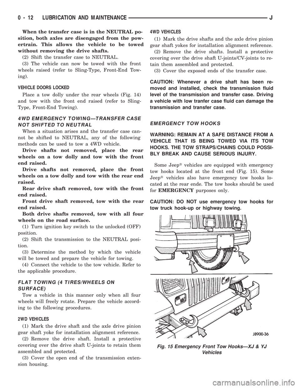
Some Jeeptvehicles are equipped with emergency
tow hooks located at the front end (Fig. 15). Some
Jeeptvehicles also have emergency tow hooks lo-
cated at the rear ende. The tow hooks should be used
forEMERGENCYpurposes only.
CAUTION: DO NOT use emergency tow hooks for
tow truck hook-up or highway towing.
Fig. 15 Emergency Front Tow HooksÐXJ & YJ
Vehicles
0 - 12 LUBRICATION AND MAINTENANCEJ
Page 16 of 1784
ENGINE OIL CHANGE AND FILTER REPLACEMENT
WARNING: CARE SHOULD BE TAKEN WHEN
CHANGING OIL. PROTECTIVE CLOTHING AND
GLOVES SHOULD BE WORN. EXPOSED SKIN
SHOULD BE WASHED WITH SOAP AND WATER TO
REMOVE ANY ENGINE OIL. DO NOT USE GASO-
LINE, THINNER, OR SOLVENTS TO REMOVE EN-
GINE OIL FROM SKIN.
REQUIRED MAINTENANCE
With normal driving conditions, engine oil and fil-
ter must be changed after each 12 000-km (7,500-
miles)/12-month interval. If the vehicle is involved
with a severe driving condition, after each 4 800-km
(3,000-miles)/3-month interval. A severe driving con-
dition includes:
²frequent short trip driving less than 24 km (15
miles);
²frequent driving in a dusty environment;
²trailer towing;
²extensive engine idling;
²sustained high-speed operation;
²desert operation;
²frequent starting and stopping;
²cold-climate operation;
²off-road driving; or
²commercial service.
OIL CHANGE AND FILTER REPLACEMENT
(1) Drain the engine oil from the crankcase. Wait
until after the engine has attained the normal oper-
ating temperature to ensure complete drainage of oil.
(2) Install the drain-hole plug with a replacement
gasket.
The oil filter should be replaced during every
engine oil change.
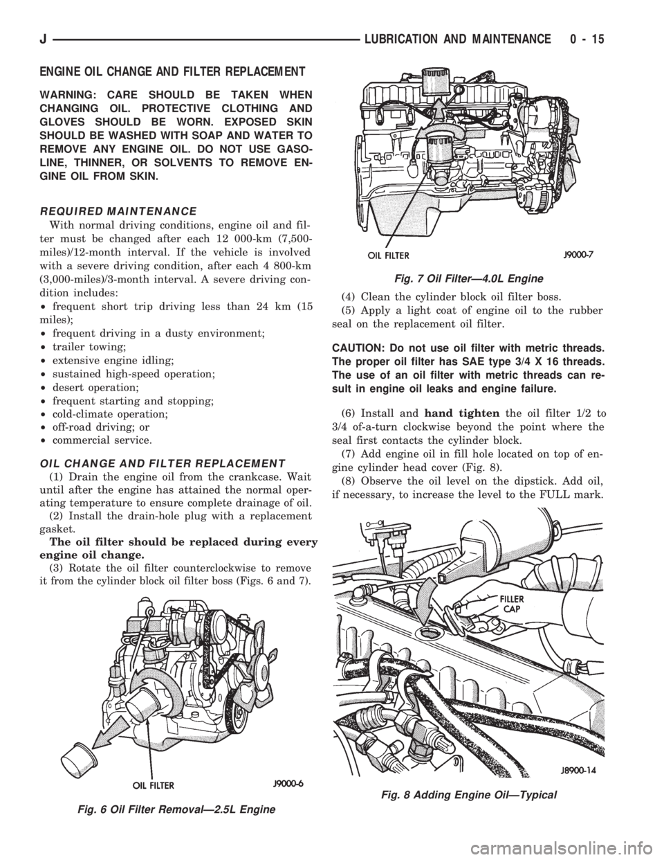
(3)
Rotate the oil filter counterclockwise to remove
it from the cylinder block oil filter boss (Figs. 6 and 7).
(4) Clean the cylinder block oil filter boss.
(5) Apply a light coat of engine oil to the rubber
seal on the replacement oil filter.
CAUTION: Do not use oil filter with metric threads.
The proper oil filter has SAE type 3/4 X 16 threads.
The use of an oil filter with metric threads can re-
sult in engine oil leaks and engine failure.
(6) Install andhand tightenthe oil filter 1/2 to
3/4 of-a-turn clockwise beyond the point where the
seal first contacts the cylinder block.
(7) Add engine oil in fill hole located on top of en-
gine cylinder head cover (Fig. 8).
(8) Observe the oil level on the dipstick. Add oil,
if necessary, to increase the level to the FULL mark.
Fig. 6 Oil Filter RemovalÐ2.5L Engine
Fig. 7 Oil FilterÐ4.0L Engine
Fig. 8 Adding Engine OilÐTypical
JLUBRICATION AND MAINTENANCE 0 - 15
Page 17 of 1784
CAUTION: Do not overfill the engine crankcase with
oil. This will cause oil aeration and result in a de-
crease in the engine oil pressure.
(9) Start the engine and observe the oil pressure
gauge or warning lamp. If the pressure does not in-
crease or the warning lamp does not go out, stop the
engine and determine the cause of the problem.
USED ENGINE OIL DISPOSAL
Care should be exercised when disposing used en-
gine oil after it has been drained from a vehicle en-
gine. Refer to the WARNING listed above.
COOLING SYSTEM
WARNING: USE EXTREME CAUTION WHEN RE-
MOVING THE RADIATOR CAP IF THE ENGINE IS
OPERATING. DO NOT PUT YOUR HANDS NEAR
THE DRIVE BELT(S), PULLEYS OR FAN BLADE. DO
NOT STAND IN A DIRECT LINE WITH THE FAN
BLADE.
RECOMMENDED MAINTENANCE
The engine coolant level should be determined at
least once a month and more often during periods of
hot weather. Add coolant as necessary.
COOLANT LEVEL
With the engine at normal operating temperature,
observe the coolant level in thecoolant recovery bot-
tle. The coolant level must be at least above the ADD
mark and preferably at the FULL mark. Add coolant
to the coolant recovery bottleonly, if necessary.
REQUIRED MAINTENANCE
Check coolant level, and inspect condition of cool-
ing system hoses and clamps after each 12 000-km
(7,500-miles).
Initially, coolant must be drained and cooling sys-
tem flushed and filled after the first 36 months of op-
eration. Thereafter, after each 24-months interval of
vehicle operation.
RECOMMENDED MAINTENANCE
The engine cooling system should be inspected for
proper operation and for component failure at least
every 12 months.
WARNING: IF THE ENGINE HAS BEEN RECENTLY
OPERATED, USE EXTREME CARE WHEN REMOV-
ING THE RADIATOR CAP TO AVOID SCALDING
WITH HOT, PRESSURIZED COOLANT.
For additional information, refer to Section 7, Cool-
ing System.COOLANT FREEZE PROTECTION
Jeeptcooling systems contain a 50/50 mixture of
anti-freeze and distilled water coolant. This is the
recommended coolant mixture for most ambient tem-
peratures. The factory-installed anti-freeze is formu-
lated to prevent corrosion on all cooling system metal
surfaces.
The degree of coolant freeze protection should be
tested every 12 months. If the coolant is contami-
nated orrustyin appearance, cooling system should
be drained and filled with a 50/50 mixture of fresh
coolant. For additional information, refer to Group
7ÐCooling System.
ENGINE AIR CLEANER FILTER ELEMENT
RECOMMENDED MAINTENANCE
Engine performance and fuel economy can be af-
fected by a restricted air cleaner filter. The filter
should be inspected on a regular basis for excessive
air restriction.
If the filter element is saturated with oil, replace
the filter element.
REQUIRED MAINTENANCE
Engine air cleaner filter must be replaced after
each 48 000-km (30,000-miles).
If a vehicle is frequently operated in dusty
areas, the air cleaner filter should be inspected
often.
FILTER ELEMENT SERVICE/REPLACEMENT
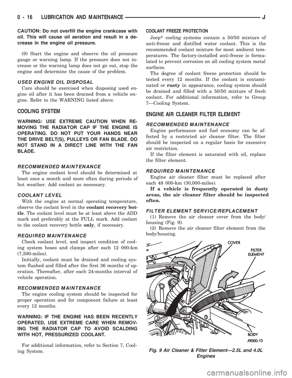
(1) Remove the air cleaner cover from the body/
housing (Fig. 9).
(2) Remove the air cleaner filter element from the
body/housing.
Fig. 9 Air Cleaner & Filter ElementÐ2.5L and 4.0L
Engines
0 - 16 LUBRICATION AND MAINTENANCEJ
Page 19 of 1784

In areas of the country where carbon monoxide lev-
els are high, gasolines are being treated with oxy-
genated materials such as MTBE, ETBE and
ethanol.
Chrysler Corporation supports these efforts toward
cleaner air and recommends the use of these gaso-
lines as they become available.
IGNITION CABLES, DISTRIBUTOR CAP AND
ROTOR
REQUIRED IGNITION SYSTEM MAINTENANCE
The ignition cables, distributor cap and rotor must
be replaced after each 96 000-km (60,000-miles). Re-
fer to Group 8DÐIgnition Systems for additional in-
formation.
IGNITION TIMING
The ignition timing for 2.5L and 4.0L engines is
not adjustable. Refer to the specifications listed on
the engine Emission Control Information Label. Re-
fer to Group 25ÐEmission Control Systems for addi-
tional information.
SPARK PLUGS
REQUIRED MAINTENANCE
The spark plugs must be replaced after each 48
000-km (30,000-miles). Refer to the Spark Plugs
chart below and to Group 8DÐIgnition Systems for
additional information.
BATTERY
RECOMMENDED MAINTENANCE
The battery electrolyte level should be checked and
the cable clamps should be inspected for corrosion.
This should be done when the oil is changed and the
oil filter is replaced.
The battery cables should be inspected for abnor-
mal clamp and battery terminal post corrosion. Ser-
vice the terminals and cable clamps as necessary.In addition, the general condition of the battery
should be determined before the start of cold and hot
weather seasons. If the battery condition is marginal
or worse, it should be replaced.
Care should be taken when disposing a bat-
tery after removal from a vehicle. Lead-acid bat-
teries are highly poisonous and, when
indiscriminately disposed, could create a prob-
lem for the environment. Contact the applicable
local city or county government agency to deter-
mine where automobile (lead-acid) batteries can
be properly disposed in the local area.
INSPECTION/SERVICE
WARNING: WEAR SAFETY GLASSES, RUBBER
GLOVES AND PROTECTIVE CLOTHING WHEN HAN-
DLING/SERVICING A BATTERY. THE BATTERY
ELECTROLYTE CONTAINS SULFURIC ACID AND
WILL CAUSE HARM IF IT CONTACTS SKIN, EYES
OR CLOTHING. IT WILL ALSO DAMAGE PAINTED
(AS WELL AS UN-PAINTED) SURFACES OF A VEHI-
CLE. IF SULFURIC ACID CONTACTS ANY OF
THESE, FLUSH IMMEDIATELY WITH LARGE
AMOUNTS OF WATER. IF SULFURIC ACID CON-
TACTS SKIN OR EYES, GET IMMEDIATE MEDICAL
ATTENTION. DO NOT SMOKE IN THE VICINITY OF
A BATTERY. KEEP OPEN FLAMES AND SPARKS
AWAY FROM BATTERY FILLER CAPS BECAUSE
EXPLOSIVE GAS IS ALWAYS PRESENT.
(1) Disconnect the battery negative cable and then
the positive cable.
(2) Clean the battery cable clamps and terminal
posts with a wire brush and a battery terminal
cleaner.
(3) Pry the battery cell filler caps upward to re-
move them and inspect each filler well (low-mainte-
nance batteries only, not applicable to maintenance-
free batteries). It could possibly be necessary to
loosen the battery holddown clamp to remove the
caps. Maintain the electrolyte level above the battery
plates and at the bottom of the filler well ring. Add
distilled water or low-mineral content drinking wa-
ter, if necessary. In freezing weather (below 0ÉC/
32ÉF), add the water just before driving to ensure
that it mixes thoroughly with the electrolyte. This
will prevent it from freezing.
(4) Remove the battery holddown strap and clean
the battery case/battery tray.Clean with bicarbonate
of soda (baking soda) and water. Rinse and dry the
battery case/tray thoroughly after cleaning.
(5) Position the battery in the tray and install the
holddown strap.Do not over-tighten the nuts.
(6) Connect the battery positive cable and then the
negative cable to the battery.
SPARK PLUGS
0 - 18 LUBRICATION AND MAINTENANCEJ
Page 25 of 1784
dye to aid in detecting the source of ATF leaks. The
use of transmission sealing additives should also be
avoided.
Black-light detection dye is factory-installed in
automatic transmissions and, unless the ATF
has been drained and re-placed, it is not neces-
sary to add dye.
ATF LEVEL
Determine the ATF level according to the following
procedure.
WARNING: USE EXTREME CAUTION WHEN THE
ENGINE IS OPERATING. DO NOT PUT YOUR
HANDS NEAR THE DRIVE BELT, PULLEYS OR FAN
BLADE. DO NOT STAND IN A DIRECT LINE WITH
THE FAN BLADE.
(1) Operate the engine and allow the automatic
transmission sufficient time to warm to the normal
operating temperature (77ÉC/170ÉF).
When at normal operating temperature, ATF
will be uncomfortable to fingertips when the
dipstick is touched. Normally, 25 km (15 miles) is
a sufficient driving distance for a transmission
to warm to normal operating temperature (77ÉC/
170ÉF).
(2) Place the vehicle on a level surface.
(3) Operate the engine at idle speed.
(4) Engage the parking brake.
(5) Place a block in front of and at the rear of one
wheel/tire to prevent vehicle movement.
(6) Depress the brake pedal and move the trans-
mission selector lever through all the positions and
then place the selector lever in NEUTRAL position.
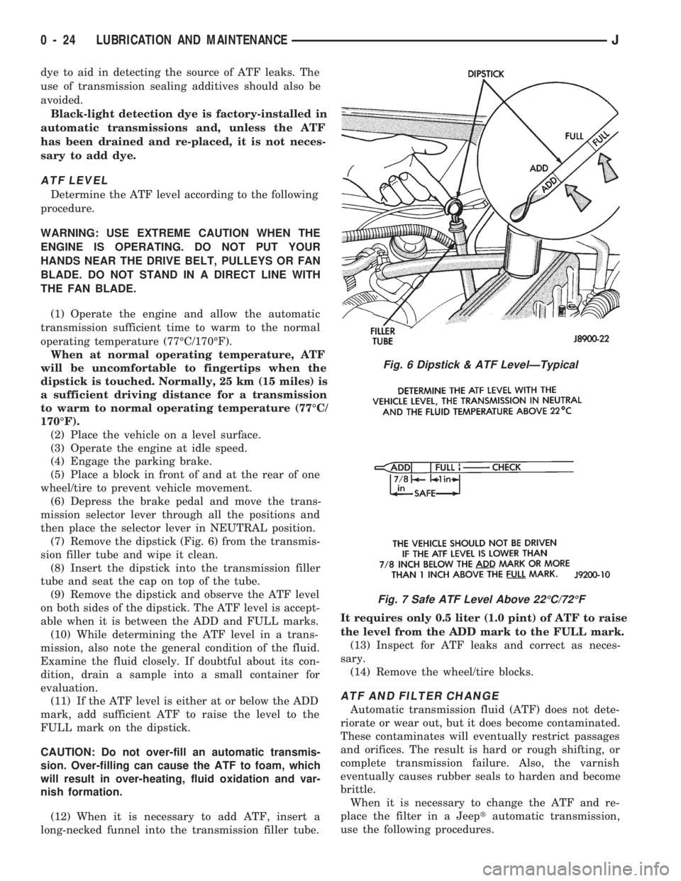
(7) Remove the dipstick (Fig. 6) from the transmis-
sion filler tube and wipe it clean.
(8) Insert the dipstick into the transmission filler
tube and seat the cap on top of the tube.
(9) Remove the dipstick and observe the ATF level
on both sides of the dipstick. The ATF level is accept-
able when it is between the ADD and FULL marks.
(10) While determining the ATF level in a trans-
mission, also note the general condition of the fluid.
Examine the fluid closely. If doubtful about its con-
dition, drain a sample into a small container for
evaluation.
(11) If the ATF level is either at or below the ADD
mark, add sufficient ATF to raise the level to the
FULL mark on the dipstick.
CAUTION: Do not over-fill an automatic transmis-
sion. Over-filling can cause the ATF to foam, which
will result in over-heating, fluid oxidation and var-
nish formation.
(12) When it is necessary to add ATF, insert a
long-necked funnel into the transmission filler tube.It requires only 0.5 liter (1.0 pint) of ATF to raise
the level from the ADD mark to the FULL mark.
(13) Inspect for ATF leaks and correct as neces-
sary.
(14) Remove the wheel/tire blocks.
ATF AND FILTER CHANGE
Automatic transmission fluid (ATF) does not dete-
riorate or wear out, but it does become contaminated.
These contaminates will eventually restrict passages
and orifices. The result is hard or rough shifting, or
complete transmission failure. Also, the varnish
eventually causes rubber seals to harden and become
brittle.
When it is necessary to change the ATF and re-
place the filter in a Jeeptautomatic transmission,
use the following procedures.
Fig. 6 Dipstick & ATF LevelÐTypical
Fig. 7 Safe ATF Level Above 22ÉC/72ÉF
0 - 24 LUBRICATION AND MAINTENANCEJ
Page 35 of 1784
(6) Inspect the disc brake caliper dust boot for cor-
rect installation, damage/tears and indications of
brake fluid leakage. Inspect the bushings and pins
for corrosion, tears and a binding condition.
(7) Pull the rear wheel cylinder dust boot back to
expose the wheel cylinder housing and inspect for
fluid leaks. Inspect the pistons and cylinder bores for
proper appearance.
(8) Inspect the brake differential warning valve
and housing for indications of leakage, kinked hoses
and loose fittings.
PARK BRAKE
(1) As applicable, engage the park brake lever or
pedal and then release it.
(2) If the park brake is functioning normally, test
it for smooth operation and vehicle-holding capabil-
ity.
(3) Inspect the park brake cables for kinks, fraying
and a binding condition.
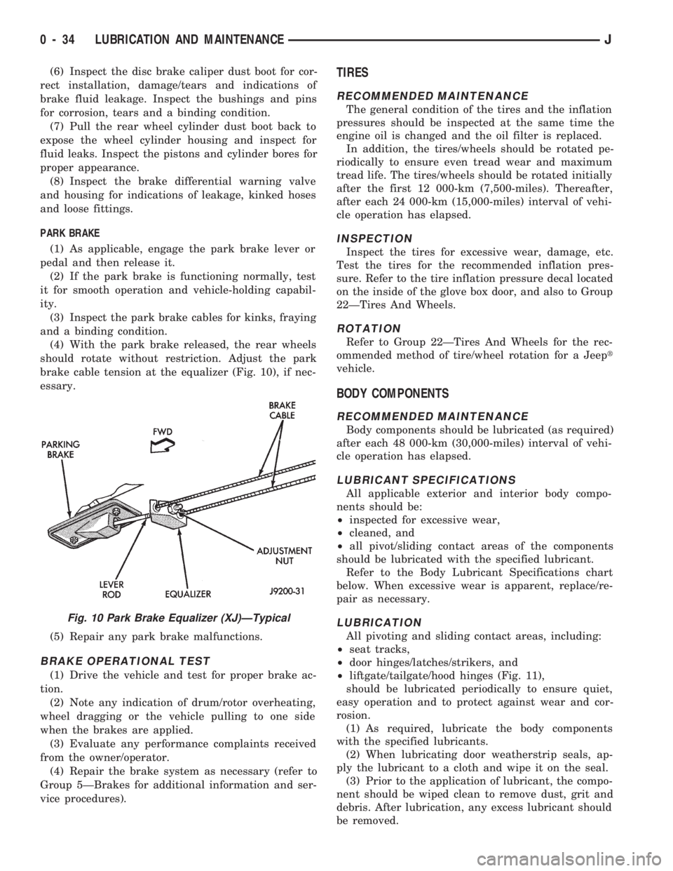
(4) With the park brake released, the rear wheels
should rotate without restriction. Adjust the park
brake cable tension at the equalizer (Fig. 10), if nec-
essary.
(5) Repair any park brake malfunctions.
BRAKE OPERATIONAL TEST
(1) Drive the vehicle and test for proper brake ac-
tion.
(2) Note any indication of drum/rotor overheating,
wheel dragging or the vehicle pulling to one side
when the brakes are applied.
(3) Evaluate any performance complaints received
from the owner/operator.
(4) Repair the brake system as necessary (refer to
Group 5ÐBrakes for additional information and ser-
vice procedures).
TIRES
RECOMMENDED MAINTENANCE
The general condition of the tires and the inflation
pressures should be inspected at the same time the
engine oil is changed and the oil filter is replaced.
In addition, the tires/wheels should be rotated pe-
riodically to ensure even tread wear and maximum
tread life. The tires/wheels should be rotated initially
after the first 12 000-km (7,500-miles). Thereafter,
after each 24 000-km (15,000-miles) interval of vehi-
cle operation has elapsed.
INSPECTION
Inspect the tires for excessive wear, damage, etc.
Test the tires for the recommended inflation pres-
sure. Refer to the tire inflation pressure decal located
on the inside of the glove box door, and also to Group
22ÐTires And Wheels.
ROTATION
Refer to Group 22ÐTires And Wheels for the rec-
ommended method of tire/wheel rotation for a Jeept
vehicle.
BODY COMPONENTS
RECOMMENDED MAINTENANCE
Body components should be lubricated (as required)
after each 48 000-km (30,000-miles) interval of vehi-
cle operation has elapsed.
LUBRICANT SPECIFICATIONS
All applicable exterior and interior body compo-
nents should be:
²inspected for excessive wear,
²cleaned, and
²all pivot/sliding contact areas of the components
should be lubricated with the specified lubricant.
Refer to the Body Lubricant Specifications chart
below. When excessive wear is apparent, replace/re-
pair as necessary.
LUBRICATION
All pivoting and sliding contact areas, including:
²seat tracks,
²door hinges/latches/strikers, and
²liftgate/tailgate/hood hinges (Fig. 11),
should be lubricated periodically to ensure quiet,
easy operation and to protect against wear and cor-
rosion.
(1) As required, lubricate the body components
with the specified lubricants.
(2) When lubricating door weatherstrip seals, ap-
ply the lubricant to a cloth and wipe it on the seal.
(3) Prior to the application of lubricant, the compo-
nent should be wiped clean to remove dust, grit and
debris. After lubrication, any excess lubricant should
be removed.
Fig. 10 Park Brake Equalizer (XJ)ÐTypical
0 - 34 LUBRICATION AND MAINTENANCEJ