1994 JEEP CHEROKEE warning
[x] Cancel search: warningPage 188 of 1784
4). The engine intake manifold serves as the vacuum
source for booster operation.
The booster is mounted on the engine compartment
side of the dash panel. The master cylinder is
mounted on attaching studs at the front of the
booster. The master cylinder central valves are di-
rectly actuated by the booster push rod.
The pedal travel sensor is mounted in the forward
face of the booster shell. The sensor plunger is actu-
ated by the booster diaphragm plate.
PEDAL TRAVEL SENSOR
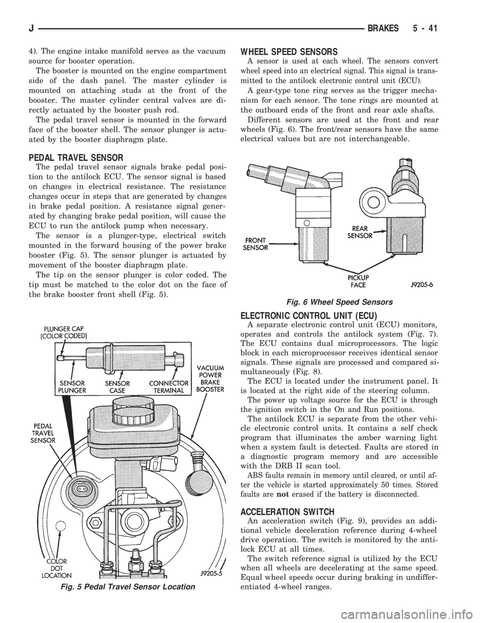
The pedal travel sensor signals brake pedal posi-
tion to the antilock ECU. The sensor signal is based
on changes in electrical resistance. The resistance
changes occur in steps that are generated by changes
in brake pedal position. A resistance signal gener-
ated by changing brake pedal position, will cause the
ECU to run the antilock pump when necessary.
The sensor is a plunger-type, electrical switch
mounted in the forward housing of the power brake
booster (Fig. 5). The sensor plunger is actuated by
movement of the booster diaphragm plate.
The tip on the sensor plunger is color coded. The
tip must be matched to the color dot on the face of
the brake booster front shell (Fig. 5).
WHEEL SPEED SENSORS
A sensor is used at each wheel. The sensors convert
wheel speed into an electrical signal. This signal is trans-
mitted to the antilock electronic control unit (ECU).
A gear-type tone ring serves as the trigger mecha-
nism for each sensor. The tone rings are mounted at
the outboard ends of the front and rear axle shafts.
Different sensors are used at the front and rear
wheels (Fig. 6). The front/rear sensors have the same
electrical values but are not interchangeable.
ELECTRONIC CONTROL UNIT (ECU)
A separate electronic control unit (ECU) monitors,
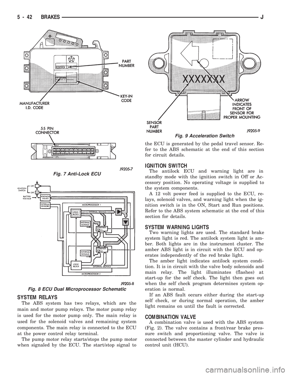
operates and controls the antilock system (Fig. 7).
The ECU contains dual microprocessors. The logic
block in each microprocessor receives identical sensor
signals. These signals are processed and compared si-
multaneously (Fig. 8).
The ECU is located under the instrument panel. It
is located at the right side of the steering column.
The power up voltage source for the ECU is through
the ignition switch in the On and Run positions.
The antilock ECU is separate from the other vehi-
cle electronic control units. It contains a self check
program that illuminates the amber warning light
when a system fault is detected. Faults are stored in
a diagnostic program memory and are accessible
with the DRB II scan tool.
ABS faults remain in memory until cleared, or until af-
ter the vehicle is started approximately 50 times. Stored
faults arenoterased if the battery is disconnected.
ACCELERATION SWITCH
An acceleration switch (Fig. 9), provides an addi-
tional vehicle deceleration reference during 4-wheel
drive operation. The switch is monitored by the anti-
lock ECU at all times.
The switch reference signal is utilized by the ECU
when all wheels are decelerating at the same speed.
Equal wheel speeds occur during braking in undiffer-
entiated 4-wheel ranges.
Fig. 5 Pedal Travel Sensor Location
Fig. 6 Wheel Speed Sensors
JBRAKES 5 - 41
Page 189 of 1784
SYSTEM RELAYS
The ABS system has two relays, which are the
main and motor pump relays. The motor pump relay
is used for the motor pump only. The main relay is
used for the solenoid valves and remaining system
components. The main relay is connected to the ECU
at the power control relay terminal.
The pump motor relay starts/stops the pump motor
when signaled by the ECU. The start/stop signal tothe ECU is generated by the pedal travel sensor. Re-
fer to the ABS schematic at the end of this section
for circuit details.
IGNITION SWITCH
The antilock ECU and warning light are in
standby mode with the ignition switch in Off or Ac-
cessory position. No operating voltage is supplied to
the system components.
A 12 volt power feed is supplied to the ECU, re-
lays, solenoid valves, and warning light when the ig-
nition switch is in the ON, Start and Run positions.
Refer to the ABS system schematic at the end of this
section for details.
SYSTEM WARNING LIGHTS
Two warning lights are used. The standard brake
system light is red. The antilock system light is am-
ber. Both lights are in the instrument cluster. The
amber ABS light is in circuit with the ECU and op-
erates independently of the red brake light.
The amber light indicates antilock system condi-
tion. It is in circuit with the valve body solenoids and
main relay. The light illuminates (flashes) at
start-up for the self check. The light then goes out
when the self check program determines system op-
eration is normal.
If an ABS fault occurs either during the start-up
self check, or during normal operation, the amber
light remains on until the fault is corrected.
COMBINATION VALVE
A combination valve is used with the ABS system
(Fig. 2). The valve contains a front/rear brake pres-
sure switch and proportioning valve. The valve is
connected between the master cylinder and hydraulic
control unit (HCU).
Fig. 7 Anti-Lock ECU
Fig. 8 ECU Dual Microprocessor Schematic
Fig. 9 Acceleration Switch
5 - 42 BRAKESJ
Page 190 of 1784
ANTILOCK BRAKE SYSTEM OPERATION
INDEX
page page
ABS Operation in Antilock Braking Mode....... 43
ABS Operation in Normal Braking Mode....... 43
Acceleration Switch Operation............... 45
ECY Operation.......................... 46HCU Pump and Pedal Travel Sensor Operation . 44
HCU Solenoid Valve Operation.............. 43
System Power-Up and Initialization........... 43
Wheel Speed Sensor Operation............. 45
SYSTEM POWER-UP AND INITIALIZATION
The antilock system is in standby mode with the
ignition switch in Off or Accessory position. The an-
tilock electrical components are not operational.
Turning the ignition switch to On or Run position
allows battery voltage to flow through the switch to
the ECU ignition terminal.
The ABS system is activated when battery voltage
is supplied to the ECU. The ECU performs a system
initialization procedure at this point. Initialization
consists of a static and dynamic self check of system
electrical components.
The static check occurs immediately after the igni-
tion switch is turned to the On position. The dynamic
check occurs when vehicle road speed reaches ap-
proximately 10 kph (6 mph). During the dynamic
check, the ECU briefly cycles the pump to verify op-
eration. The HCU solenoids are checked continu-
ously.
If an ABS component exhibits a fault during ini-
tialization, the ECU illuminates the amber warning
light and registers a fault code in the microprocessor
memory.
ABS OPERATION IN NORMAL BRAKING MODE
The ECU monitors wheel speed sensor inputs con-
tinuously while the vehicle is in motion. However,
the ECU will not activate any ABS components as
long as sensor inputs and the acceleration switch in-
dicate normal braking.
During normal braking, the master cylinder, power
booster and wheel brake units all function as they
would in a vehicle without ABS. The HCU compo-
nents are not activated.
ABS OPERATION IN ANTILOCK BRAKING MODE
The purpose of the antilock system is to prevent
wheel lockup during periods of high wheel slip. Pre-
venting lockup helps maintain vehicle braking action
and steering control.
The antilock ECU activates the system whenever
sensor signals indicate periods of high wheel slip.
High wheel slip can be described as the point where
wheel rotation begins approaching zero (or lockup)
during braking. Periods of high wheel slip occur
when brake stops involve high pedal pressure and
rate of vehicle deceleration.The antilock system retards lockup during high
slip conditions by modulating fluid apply pressure to
the wheel brake units.
Brake fluid apply pressure is modulated according
to wheel speed, degree of slip and rate of decelera-
tion. A sensor at each wheel converts wheel speed
into electrical signals. These signals are transmitted
to the ECU for processing and determination of
wheel slip and deceleration rate.
The Jeep ABS system has three fluid pressure con-
trol channels. The front brakes are controlled sepa-
rately and the rear brakes in tandem (Fig. 10). A
speed sensor input signal indicating high slip condi-
tions activates the ECU antilock program.
Two solenoid valves are used in each antilock con-
trol channel (Fig. 11). The valves are all located
within the HCU valve body and work in pairs to ei-
ther increase, hold, or decrease apply pressure as
needed in the individual control channels.
The solenoid valves are not static during antilock
braking. They are cycled continuously to modulate
pressure. Solenoid cycle time in antilock mode can be
measured in milliseconds.
HCU SOLENOID VALVE OPERATION
Normal Braking
During normal braking, the HCU solenoid valves
and pump are not activated. The master cylinder and
power booster operate the same as a vehicle without
an ABS brake system.
Antilock Pressure Modulation
Solenoid valve pressure modulation occurs in three
stages which are: pressure increase, pressure hold,
and pressure decrease. The valves are all contained
in the valve body portion of the HCU.
Pressure Decrease
The outlet valve is opened and the inlet valve is
closed during the pressure decrease cycle (Fig. 11).
A pressure decrease cycle is initiated when speed
sensor signals indicate high wheel slip at one or
more wheels. At this point, the ECU opens the outlet
valve. Opening the outlet valve also opens the hy-
draulic return circuit to the master cylinder reser-
JANTILOCK BRAKE SYSTEM OPERATION 5 - 43
Page 206 of 1784
PARKING BRAKE LEVER REMOVAL (XJ WITH FULL
CONSOLE)
(1) Release parking brakes, if necessary.
(2) Raise vehicle.
(3) Remove adjusting nut from tensioner rod. Then
temporarily secure equalizer to nearby chassis com-
ponent with wire.
(4) Remove nuts attaching lever support plate to
underside of floorpan.
(5) Lower vehicle.
(6) On models with manual transmission, remove
shift knob, boot and bezel.
(7) On models with automatic transmission, re-
move shift handle cap and remove plunger, spring
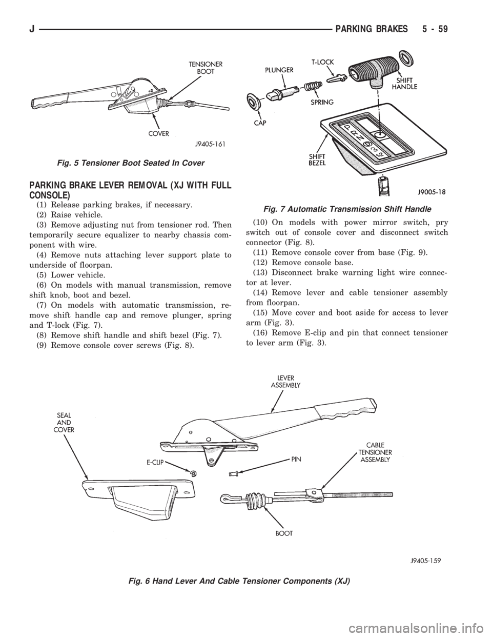
and T-lock (Fig. 7).
(8) Remove shift handle and shift bezel (Fig. 7).
(9) Remove console cover screws (Fig. 8).(10) On models with power mirror switch, pry
switch out of console cover and disconnect switch
connector (Fig. 8).
(11) Remove console cover from base (Fig. 9).
(12) Remove console base.
(13) Disconnect brake warning light wire connec-
tor at lever.
(14) Remove lever and cable tensioner assembly
from floorpan.
(15) Move cover and boot aside for access to lever
arm (Fig. 3).
(16) Remove E-clip and pin that connect tensioner
to lever arm (Fig. 3).
Fig. 6 Hand Lever And Cable Tensioner Components (XJ)
Fig. 5 Tensioner Boot Seated In Cover
Fig. 7 Automatic Transmission Shift Handle
JPARKING BRAKES 5 - 59
Page 207 of 1784
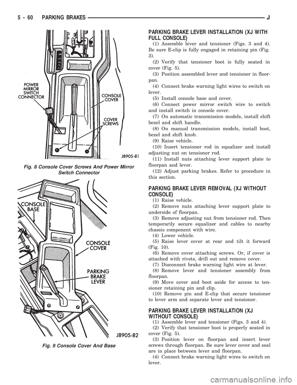
PARKING BRAKE LEVER INSTALLATION (XJ WITH
FULL CONSOLE)
(1) Assemble lever and tensioner (Figs. 3 and 4).
Be sure E-clip is fully engaged in retaining pin (Fig.
3).
(2) Verify that tensioner boot is fully seated in
cover (Fig. 5).
(3) Position assembled lever and tensioner in floor-
pan.
(4) Connect brake warning light wires to switch on
lever.
(5) Install console base and cover.
(6) Connect power mirror switch wire to switch
and install switch in console cover.
(7) On automatic transmission models, install shift
bezel and shift handle.
(8) On manual transmission models, install boot,
bezel and shift knob.
(9) Raise vehicle.
(10) Insert tensioner rod in equalizer and install
adjusting nut on tensioner rod.
(11) Install nuts attaching lever support plate to
floorpan and lever.
(12) Adjust parking brakes. Refer to procedure in
this section.
PARKING BRAKE LEVER REMOVAL (XJ WITHOUT
CONSOLE)
(1) Raise vehicle.
(2) Remove nuts attaching lever support plate to
underside of floorpan.
(3) Remove adjusting nut from tensioner rod. Then
temporarily secure equalizer and cables to nearby
chassis component with wire.
(4) Lower vehicle.
(5) Raise lever cover at rear and tilt it forward
(Fig. 10).
(6) Remove cover attaching screws. Or, if cover is
attached with rivets, drill out and remove cover.
(7) Disconnect brake warning light wire at lever.
(8) Remove lever and tensioner assembly from
floorpan.
(9) Move cover and boot aside for access to ten-
sioner retaining pin and clip.
(10) Remove pin and E-clip that secure tensioner
to lever arm and separate lever and tensioner.
PARKING BRAKE LEVER INSTALLATION (XJ
WITHOUT CONSOLE)
(1) Assemble lever and tensioner (Figs. 3 and 4).
(2) Verify that tensioner boot is properly seated in
cover (Fig. 5).
(3) Position lever on floorpan and insert lever
screws through floorpan. Be sure lever cover and seal
are in place between lever and floorpan.
(4) Connect brake warning light wires to switch on
lever.
Fig. 8 Console Cover Screws And Power Mirror
Switch Connector
Fig. 9 Console Cover And Base
5 - 60 PARKING BRAKESJ
Page 208 of 1784
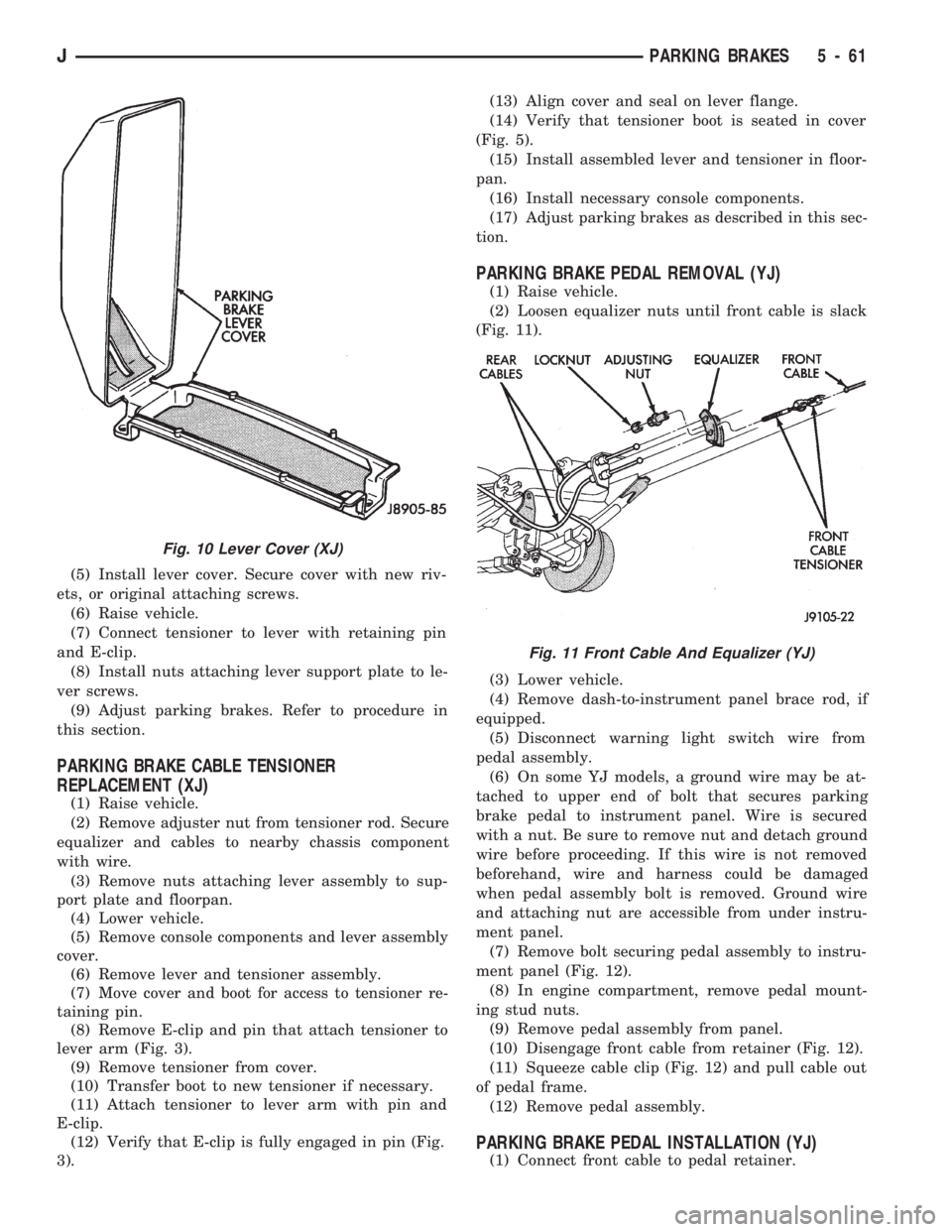
(5) Install lever cover. Secure cover with new riv-
ets, or original attaching screws.
(6) Raise vehicle.
(7) Connect tensioner to lever with retaining pin
and E-clip.
(8) Install nuts attaching lever support plate to le-
ver screws.
(9) Adjust parking brakes. Refer to procedure in
this section.
PARKING BRAKE CABLE TENSIONER
REPLACEMENT (XJ)
(1) Raise vehicle.
(2) Remove adjuster nut from tensioner rod. Secure
equalizer and cables to nearby chassis component
with wire.
(3) Remove nuts attaching lever assembly to sup-
port plate and floorpan.
(4) Lower vehicle.
(5) Remove console components and lever assembly
cover.
(6) Remove lever and tensioner assembly.
(7) Move cover and boot for access to tensioner re-
taining pin.
(8) Remove E-clip and pin that attach tensioner to
lever arm (Fig. 3).
(9) Remove tensioner from cover.
(10) Transfer boot to new tensioner if necessary.
(11) Attach tensioner to lever arm with pin and
E-clip.
(12) Verify that E-clip is fully engaged in pin (Fig.
3).(13) Align cover and seal on lever flange.
(14) Verify that tensioner boot is seated in cover
(Fig. 5).
(15) Install assembled lever and tensioner in floor-
pan.
(16) Install necessary console components.
(17) Adjust parking brakes as described in this sec-
tion.
PARKING BRAKE PEDAL REMOVAL (YJ)
(1) Raise vehicle.
(2) Loosen equalizer nuts until front cable is slack
(Fig. 11).
(3) Lower vehicle.
(4) Remove dash-to-instrument panel brace rod, if
equipped.
(5) Disconnect warning light switch wire from
pedal assembly.
(6) On some YJ models, a ground wire may be at-
tached to upper end of bolt that secures parking
brake pedal to instrument panel. Wire is secured
with a nut. Be sure to remove nut and detach ground
wire before proceeding. If this wire is not removed
beforehand, wire and harness could be damaged
when pedal assembly bolt is removed. Ground wire
and attaching nut are accessible from under instru-
ment panel.
(7) Remove bolt securing pedal assembly to instru-
ment panel (Fig. 12).
(8) In engine compartment, remove pedal mount-
ing stud nuts.
(9) Remove pedal assembly from panel.
(10) Disengage front cable from retainer (Fig. 12).
(11) Squeeze cable clip (Fig. 12) and pull cable out
of pedal frame.
(12) Remove pedal assembly.
PARKING BRAKE PEDAL INSTALLATION (YJ)
(1) Connect front cable to pedal retainer.
Fig. 10 Lever Cover (XJ)
Fig. 11 Front Cable And Equalizer (YJ)
JPARKING BRAKES 5 - 61
Page 209 of 1784
(2) Position pedal assembly on panel and install
mounting stud nuts and pedal-to-dash bolt.
(3) Install ground wire on upper end of pedal-to-
dash bolt and secure wire with attaching nut.
(4) Connect warning light switch wire to pedal
connector.
(5) Install dash-to-instrument panel brace rod, if
equipped.
(6) Raise vehicle and adjust brake cables. Refer to
procedure in Service Adjustment section.
PARKING BRAKE REAR CABLE REPLACEMENT (XJ)
(1) Raise vehicle and loosen equalizer nuts until
rear cables are slack.
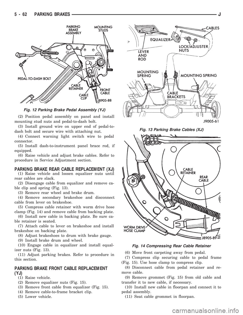
(2) Disengage cable from equalizer and remove ca-
ble clip and spring (Fig. 13).
(3) Remove rear wheel and brake drum.
(4) Remove secondary brakeshoe and disconnect
cable from lever on brakeshoe.
(5) Compress cable retainer with worm drive hose
clamp (Fig. 14) and remove cable from backing plate.
(6) Install new cable in backing plate. Be sure ca-
ble retainer is seated.
(7) Attach cable to lever on brakeshoe and install
brakeshoe on backing plate.
(8) Adjust brakeshoes to drum with brake gauge.
(9) Install brake drum and wheel.
(10) Engage cable in equalizer and install equal-
izer nuts (Fig. 13).
(11) Adjust parking brakes. Refer to procedure in
this section.
PARKING BRAKE FRONT CABLE REPLACEMENT
(YJ)
(1) Raise vehicle.
(2) Remove equalizer nuts (Fig. 15).
(3) Remove front cable from equalizer (Fig. 15).
(4) Remove cable-to-frame bracket clip.
(5) Lower vehicle.(6) Move front carpeting away from pedal.
(7) Compress clip securing cable to pedal frame
(Fig. 15). Use hose clamp to compress clip.
(8) Disconnect cable from pedal retainer and re-
move cable.
(9) Remove grommet (Fig. 15) from old cable and
transfer it to new cable, if necessary.
(10) Install new cable in floorpan and connect it to
pedal assembly.
(11) Seat cable grommet in floorpan.
Fig. 12 Parking Brake Pedal Assembly (YJ)
Fig. 13 Parking Brake Cables (XJ)
Fig. 14 Compressing Rear Cable Retainer
5 - 62 PARKING BRAKESJ
Page 225 of 1784
CLUTCH SERVICE
INDEX
page page
Clutch Cover and Disc Installation............ 10
Clutch Cover and Disc Removal............. 10
Clutch Fluid Level........................ 14
Clutch Housing Replacement................ 11
Clutch Hydraulic Linkage Installation.......... 12
Clutch Hydraulic Linkage Removal........... 11Clutch Pedal Installation................... 15
Clutch Pedal Removal..................... 15
Clutch Safety Precautions.................. 10
Flywheel Service......................... 15
Pilot Bearing Replacement................. 11
Release Bearing Replacement............... 11
CLUTCH SAFETY PRECAUTIONS
WARNING: EXERCISE CARE WHEN SERVICING
CLUTCH COMPONENTS. DUST AND DIRT ON
CLUTCH PARTS USE MAY CONTAIN ASBESTOS FI-
BERS. BREATHING EXCESSIVE CONCENTRATIONS
OF THESE FIBERS CAN CAUSE SERIOUS BODILY
HARM. WEAR A RESPIRATOR DURING SERVICE
AND NEVER CLEAN CLUTCH COMPONENTS WITH
COMPRESSED AIR OR WITH A DRY BRUSH. EI-
THER CLEAN THE COMPONENTS WITH A WATER
DAMPENED RAGS OR USE A VACUUM CLEANER
SPECIFICALLY DESIGNED FOR REMOVING ASBES-
TOS FIBERS AND DUST. DO NOT CREATE DUST
BY SANDING A CLUTCH DISC. REPLACE THE DISC
IF THE FRICTION MATERIAL IS DAMAGED OR
CONTAMINATED. DISPOSE OF ALL DUST AND
DIRT CONTAINING ASBESTOS FIBERS IN SEALED
BAGS OR CONTAINERS. THIS WILL HELP MINIMIZE
EXPOSURE TO YOURSELF AND TO OTHERS. FOL-
LOW ALL RECOMMENDED SAFETY PRACTICES
PRESCRIBED BY THE OCCUPATIONAL SAFETY
AND HEALTH ADMINISTRATION (OSHA) AND THE
ENVIRONMENTAL SAFETY AGENCY (EPA), FOR
THE HANDLING AND DISPOSAL OF PRODUCTS
CONTAINING ASBESTOS.
CLUTCH COVER AND DISC REMOVAL
(1) Remove transmission. Refer to procedures in
Group 21.
(2) If original clutch cover will be reinstalled,
mark position of cover on flywheel for assembly ref-
erence. Use paint or a scriber for this purpose.
(3) If clutch cover is to be replaced, cover bolts can
be removed in any sequence. However, if original
cover will be reinstalled, loosen cover bolts evenly
and in rotation to relieve spring tension equally.
This is necessary avoid warping cover.
(4) Remove cover bolts and remove cover and disc
(Fig. 2).
CLUTCH COVER AND DISC INSTALLATION
(1) Lightly scuff sand flywheel face with 180 grit
emery cloth. Then clean surface with a wax and
grease remover.
(2) Lubricate pilot bearing with Mopar high tem-
perature bearing grease.
(3) Check runout and free operation of new clutch
disc as follows:
(a) Slide disc onto transmission input shaft
splines. Disc should slide freely on splines.
(b) Leave disc on shaft and check face runout
with dial indicator. Check runout at disc hub and
about 6 mm (1/4 in.) from outer edge of facing.
(c) Face runout should not exceed 0.5 mm (0.020
in.). Obtain another clutch disc if runout exceeds
this limit.
(4) Position clutch disc on flywheel. Be sure side of
disc marked flywheel side is positioned against fly-
wheel (Fig. 2). If disc is not marked, be sure flat side
of disc hub is toward flywheel.
(5) Insert clutch alignment tool in clutch disc (Fig.
3).
(6) Insert alignment tool in pilot bearing and posi-
tion disc on flywheel. Be sure disc hub is positioned
correctly. Side of hub marked Flywheel Side should
face flywheel (Fig. 2). If disc is not marked, place flat
side of disc against flywheel.
(7) Position clutch cover over disc and on flywheel
(Fig. 3).
(8) Install clutch cover bolts finger tight.
(9) Tighten cover bolts evenly and in rotation a
few threads at a time.Cover bolts must be tight-
ened evenly and to specified torque to avoid dis-
torting cover. Tightening torques are 31 Nzm (23
ft. lbs.) on 2.5L engines and 54 Nzm (40 ft. lbs.) on
4.0L engines.
(10) Apply light coat of Mopar high temperature
bearing grease to pilot bearing hub and splines of
transmission input shaft.Do not overlubricate
shaft splines. This will result in grease contami-
nation of disc.
(11) Install transmission (Fig. 4). Refer to proce-
dures in Group 21.
6 - 10 CLUTCH SERVICEJ