1994 JEEP CHEROKEE warning
[x] Cancel search: warningPage 270 of 1784
ENGINE BLOCK HEATER
GENERAL INFORMATION
DESCRIPTION AND OPERATION
An optional engine block heater is available for all
models. The heater is equipped with a power cord.
The cord is attached to an engine compartment com-
ponent with tie-straps. The heater warms the engine
providing easier engine starting and faster warm-up
in low temperatures. The heater is mounted in a core
hole of the engine cylinder block (in place of a freeze
plug) with the heating element immersed in engine
coolant. Connect the power cord to a grounded 110-
120 volt AC electrical outlet with a grounded, three-
wire extension cord.
WARNING: DO NOT OPERATE ENGINE UNLESS
BLOCK HEATER CORD HAS BEEN DISCONNECTED
FROM POWER SOURCE AND SECURED IN PLACE.
BLOCK HEATER SPECIFICATIONS
²2.5L Engine: 115 Volts 400 Watts
²4.0L Engine: 120 Volts 600 Watts
REMOVAL
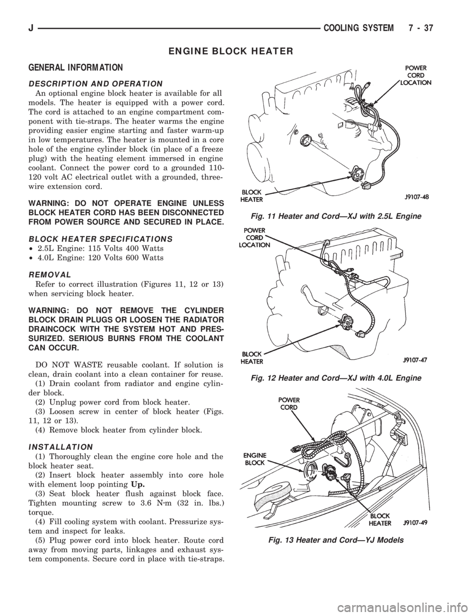
Refer to correct illustration (Figures 11, 12 or 13)
when servicing block heater.
WARNING: DO NOT REMOVE THE CYLINDER
BLOCK DRAIN PLUGS OR LOOSEN THE RADIATOR
DRAINCOCK WITH THE SYSTEM HOT AND PRES-
SURIZED. SERIOUS BURNS FROM THE COOLANT
CAN OCCUR.
DO NOT WASTE reusable coolant. If solution is
clean, drain coolant into a clean container for reuse.
(1) Drain coolant from radiator and engine cylin-
der block.
(2) Unplug power cord from block heater.
(3) Loosen screw in center of block heater (Figs.
11, 12 or 13).
(4) Remove block heater from cylinder block.
INSTALLATION
(1) Thoroughly clean the engine core hole and the
block heater seat.
(2) Insert block heater assembly into core hole
with element loop pointingUp.
(3) Seat block heater flush against block face.
Tighten mounting screw to 3.6 Nzm (32 in. lbs.)
torque.
(4) Fill cooling system with coolant. Pressurize sys-
tem and inspect for leaks.
(5) Plug power cord into block heater. Route cord
away from moving parts, linkages and exhaust sys-
tem components. Secure cord in place with tie-straps.
Fig. 11 Heater and CordÐXJ with 2.5L Engine
Fig. 12 Heater and CordÐXJ with 4.0L Engine
Fig. 13 Heater and CordÐYJ Models
JCOOLING SYSTEM 7 - 37
Page 274 of 1784
ELECTRICAL
GROUP INDEX
Group Group
AUDIO SYSTEMS....................... 8F
BATTERY/STARTER/GENERATOR SERVICE . . 8B
BATTERY/STARTING/CHARGING SYSTEMS
DIAGNOSTICS........................ 8A
CHIME/WARNING BUZZER SYSTEM....... 8U
HORNS............................... 8G
IGNITION SYSTEMS.................... 8D
INSTRUMENT PANEL AND GAUGES........ 8E
LAMPS............................... 8L
OVERHEAD CONSOLE................... 8CPOWER LOCKS........................ 8P
POWER MIRRORS...................... 8T
POWER SEAT.......................... 8R
POWER WINDOWS..................... 8S
REAR WINDOW DEFOGGER.............. 8N
TURN SIGNALS AND HAZARD WARNING
FLASHERS........................... 8J
VEHICLE SPEED CONTROL SYSTEM....... 8H
WINDSHIELD WIPERS AND WASHERS..... 8K
WIRING DIAGRAMS.................... 8W
BATTERY/STARTING/CHARGING SYSTEMS DIAGNOSTICS
CONTENTS
page page
BATTERY TEST PROCEDURES............. 2
ENGINE STARTER MOTOR TEST
PROCEDURES ON VEHICLE.............. 9GENERATOR TEST PROCEDURES ON
VEHICLE............................. 14
IGNITION OFF DRAW (IOD) DIAGNOSIS...... 8
USING ON-BOARD DIAGNOSTIC SYSTEM.... 19
GENERAL INFORMATION
The battery, starting, and charging systems oper-
ate with one another, and therefore, must be thor-
oughly tested as a complete system. In order for the
vehicle to start and charge properly, it must have a
battery that will perform to specifications. The
starter motor, generator, wiring, and electronics also
must perform within specifications. Group 8A covers
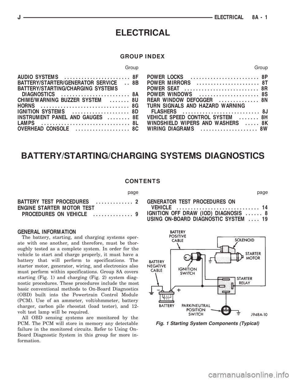
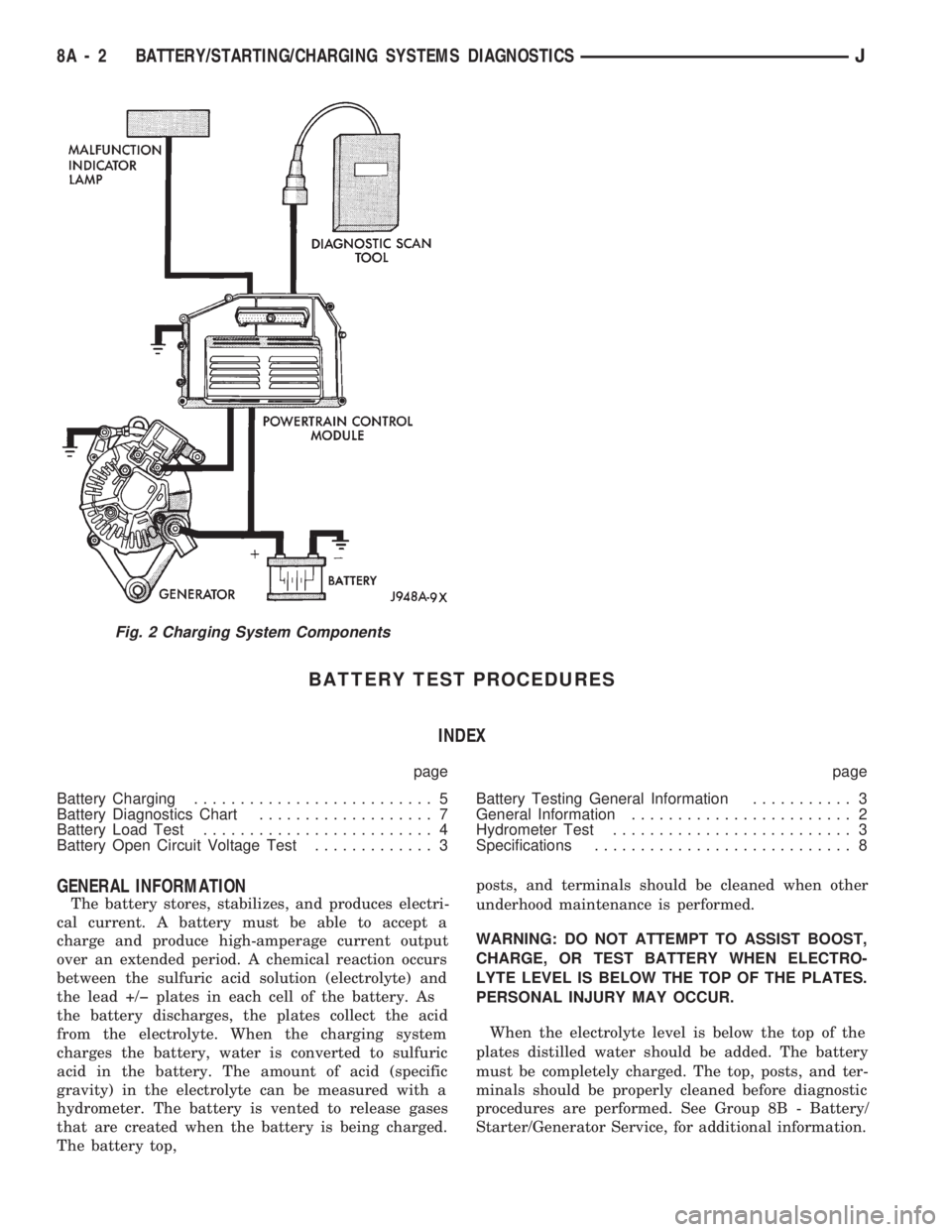
starting (Fig. 1) and charging (Fig. 2) system diag-
nostic procedures. These procedures include the most
basic conventional methods to On-Board Diagnostics
(OBD) built into the Powertrain Control Module
(PCM). Use of an ammeter, volt/ohmmeter, battery
charger, carbon pile rheostat (load tester), and 12-
volt test lamp will be required.
All OBD sensing systems are monitored by the
PCM. The PCM will store in memory any detectable
failure in the monitored circuits. Refer to Using On-
Board Diagnostic System in this group for more in-
formation.
Fig. 1 Starting System Components (Typical)
JELECTRICAL 8A - 1
Page 275 of 1784
BATTERY TEST PROCEDURES
INDEX
page page
Battery Charging.......................... 5
Battery Diagnostics Chart................... 7
Battery Load Test......................... 4
Battery Open Circuit Voltage Test............. 3Battery Testing General Information........... 3
General Information........................ 2
Hydrometer Test.......................... 3
Specifications............................ 8
GENERAL INFORMATION
The battery stores, stabilizes, and produces electri-
cal current. A battery must be able to accept a
charge and produce high-amperage current output
over an extended period. A chemical reaction occurs
between the sulfuric acid solution (electrolyte) and
the lead +/þ plates in each cell of the battery. As
the battery discharges, the plates collect the acid
from the electrolyte. When the charging system
charges the battery, water is converted to sulfuric
acid in the battery. The amount of acid (specific
gravity) in the electrolyte can be measured with a
hydrometer. The battery is vented to release gases
that are created when the battery is being charged.
The battery top,posts, and terminals should be cleaned when other
underhood maintenance is performed.
WARNING: DO NOT ATTEMPT TO ASSIST BOOST,
CHARGE, OR TEST BATTERY WHEN ELECTRO-
LYTE LEVEL IS BELOW THE TOP OF THE PLATES.
PERSONAL INJURY MAY OCCUR.
When the electrolyte level is below the top of the
plates distilled water should be added. The battery
must be completely charged. The top, posts, and ter-
minals should be properly cleaned before diagnostic
procedures are performed. See Group 8B - Battery/
Starter/Generator Service, for additional information.
Fig. 2 Charging System Components
8A - 2 BATTERY/STARTING/CHARGING SYSTEMS DIAGNOSTICSJ
Page 277 of 1784
Battery/Starter/Generator Service for instructions. To
test battery no load voltage, perform the following
operation:
(1) Before measuring open circuit voltage, the sur-
face charge must be removed from plates. Turn head-
lamps on for 15 seconds then allow up to 5 minutes
for voltage to stabilize.
(2) Remove both battery cables, negative first.
(3) Using a voltmeter connected to the battery
posts (see instructions provided with voltmeter) mea-
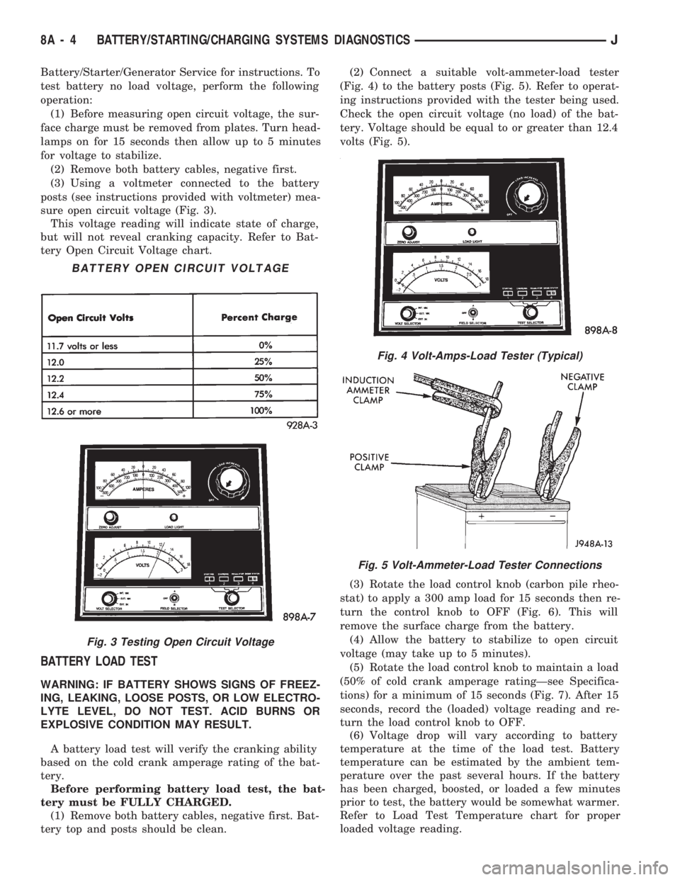
sure open circuit voltage (Fig. 3).
This voltage reading will indicate state of charge,
but will not reveal cranking capacity. Refer to Bat-
tery Open Circuit Voltage chart.
BATTERY LOAD TEST
WARNING: IF BATTERY SHOWS SIGNS OF FREEZ-
ING, LEAKING, LOOSE POSTS, OR LOW ELECTRO-
LYTE LEVEL, DO NOT TEST. ACID BURNS OR
EXPLOSIVE CONDITION MAY RESULT.
A battery load test will verify the cranking ability
based on the cold crank amperage rating of the bat-
tery.
Before performing battery load test, the bat-
tery must be FULLY CHARGED.
(1) Remove both battery cables, negative first. Bat-
tery top and posts should be clean.(2) Connect a suitable volt-ammeter-load tester
(Fig. 4) to the battery posts (Fig. 5). Refer to operat-
ing instructions provided with the tester being used.
Check the open circuit voltage (no load) of the bat-
tery. Voltage should be equal to or greater than 12.4
volts (Fig. 5).
(3) Rotate the load control knob (carbon pile rheo-
stat) to apply a 300 amp load for 15 seconds then re-
turn the control knob to OFF (Fig. 6). This will
remove the surface charge from the battery.
(4) Allow the battery to stabilize to open circuit
voltage (may take up to 5 minutes).
(5) Rotate the load control knob to maintain a load
(50% of cold crank amperage ratingÐsee Specifica-
tions) for a minimum of 15 seconds (Fig. 7). After 15
seconds, record the (loaded) voltage reading and re-
turn the load control knob to OFF.
(6) Voltage drop will vary according to battery
temperature at the time of the load test. Battery
temperature can be estimated by the ambient tem-
perature over the past several hours. If the battery
has been charged, boosted, or loaded a few minutes
prior to test, the battery would be somewhat warmer.
Refer to Load Test Temperature chart for proper
loaded voltage reading.
Fig. 4 Volt-Amps-Load Tester (Typical)
Fig. 5 Volt-Ammeter-Load Tester Connections
BATTERY OPEN CIRCUIT VOLTAGE
Fig. 3 Testing Open Circuit Voltage
8A - 4 BATTERY/STARTING/CHARGING SYSTEMS DIAGNOSTICSJ
Page 278 of 1784
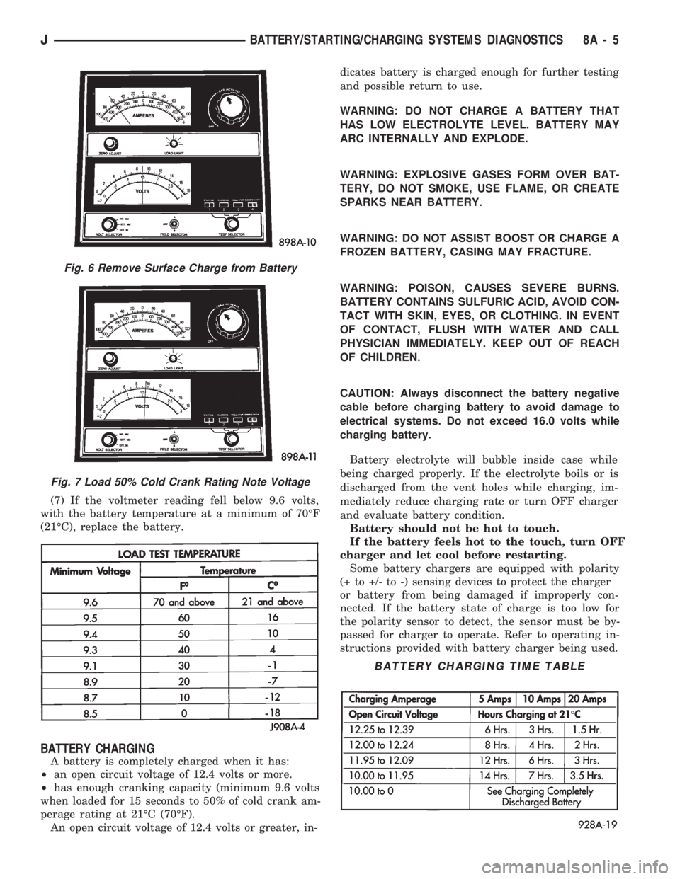
(7) If the voltmeter reading fell below 9.6 volts,
with the battery temperature at a minimum of 70ÉF
(21ÉC), replace the battery.
BATTERY CHARGING
A battery is completely charged when it has:
²an open circuit voltage of 12.4 volts or more.
²has enough cranking capacity (minimum 9.6 volts
when loaded for 15 seconds to 50% of cold crank am-
perage rating at 21ÉC (70ÉF).
An open circuit voltage of 12.4 volts or greater, in-dicates battery is charged enough for further testing
and possible return to use.
WARNING: DO NOT CHARGE A BATTERY THAT
HAS LOW ELECTROLYTE LEVEL. BATTERY MAY
ARC INTERNALLY AND EXPLODE.
WARNING: EXPLOSIVE GASES FORM OVER BAT-
TERY, DO NOT SMOKE, USE FLAME, OR CREATE
SPARKS NEAR BATTERY.
WARNING: DO NOT ASSIST BOOST OR CHARGE A
FROZEN BATTERY, CASING MAY FRACTURE.
WARNING: POISON, CAUSES SEVERE BURNS.
BATTERY CONTAINS SULFURIC ACID, AVOID CON-
TACT WITH SKIN, EYES, OR CLOTHING. IN EVENT
OF CONTACT, FLUSH WITH WATER AND CALL
PHYSICIAN IMMEDIATELY. KEEP OUT OF REACH
OF CHILDREN.
CAUTION: Always disconnect the battery negative
cable before charging battery to avoid damage to
electrical systems. Do not exceed 16.0 volts while
charging battery.
Battery electrolyte will bubble inside case while
being charged properly. If the electrolyte boils or is
discharged from the vent holes while charging, im-
mediately reduce charging rate or turn OFF charger
and evaluate battery condition.
Battery should not be hot to touch.
If the battery feels hot to the touch, turn OFF
charger and let cool before restarting.
Some battery chargers are equipped with polarity
(+ to +/- to -) sensing devices to protect the charger
or battery from being damaged if improperly con-
nected. If the battery state of charge is too low for
the polarity sensor to detect, the sensor must be by-
passed for charger to operate. Refer to operating in-
structions provided with battery charger being used.
Fig. 6 Remove Surface Charge from Battery
Fig. 7 Load 50% Cold Crank Rating Note Voltage
BATTERY CHARGING TIME TABLE
JBATTERY/STARTING/CHARGING SYSTEMS DIAGNOSTICS 8A - 5
Page 279 of 1784
After the battery has been charged to 12.4 volts or
greater, perform a load test to determine cranking
capacity. If the battery will endure a load test, re-
turn the battery to use. If battery will not endure a
load test, it must be replaced. Clean and inspect bat-
tery holddowns, tray, terminals, posts, and top before
completing service, see Group 8B - Battery/Starter/
Generator Service.
CHARGING TIME REQUIRED
The time required to charge a battery will vary de-
pending upon the following factors:
(1)Size of BatteryÐA completely discharged
large, heavy-duty battery requires more than twice
the recharging time as a completely discharged small
capacity battery.
WARNING: NEVER EXCEED 20 AMPS WHEN
CHARGING A COLD (-1ÉC/30ÉF) BATTERY, PER-
SONAL INJURY MAY RESULT.
(2)TemperatureÐA longer time will be needed
to charge a battery at -18ÉC (0ÉF) than at 27ÉC
(80ÉF). When a fast charger is connected to a cold
battery, current accepted by battery will be very low
at first. Then, in time, the battery will accept a
higher rate as battery warms.
(3)Charger CapacityÐA charger, that supplies
only 5 amperes, will require a longer charging time
than a charger that supplies 20 amperes or more.
(4)State Of ChargeÐA completely discharged
battery requires more charging time than a partially
charged battery. Electrolyte is nearly pure water in a
completely discharged battery. At first the charging
current amperage will be low. As the battery charges
the specific gravity of the electrolyte will rise slowly.
CHARGING COMPLETELY DISCHARGED
BATTERY
The following procedure should be used to recharge
a completely discharged battery. Unless procedure is
properly followed, a good battery may be needlessly
replaced.
(1) Measure voltage at battery posts with a volt-
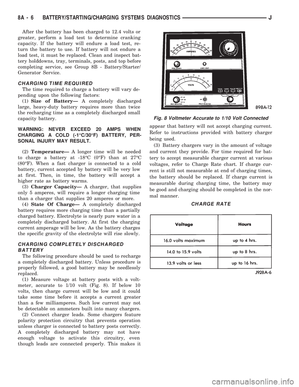
meter, accurate to 1/10 volt (Fig. 8). If below 10
volts, then charge current will be low and it could
take some time before it accepts a current greater
than a few milliamperes. Such low current may not
be detectable on ammeters built into many chargers.
(2) Connect charger leads. Some chargers feature
polarity protection circuitry that prevents operation
unless charger is connected to battery posts correctly.
A completely discharged battery may not have
enough voltage to activate this circuitry, even
though leads are connected properly. This makes itappear that battery will not accept charging current.
Refer to instructions provided with battery charger
being used.
(3) Battery chargers vary in the amount of voltage
and current they provide. For time required for bat-
tery to accept measurable charger current at various
voltages, refer to Charge Rate chart. If charge cur-
rent is still not measurable at end of charging times,
the battery should be replaced. If charge current is
measurable during charging time, the battery may
be good and charging should be completed in the nor-
mal manner.
Fig. 8 Voltmeter Accurate to 1/10 Volt Connected
CHARGE RATE
8A - 6 BATTERY/STARTING/CHARGING SYSTEMS DIAGNOSTICSJ
Page 294 of 1784
BATTERY/STARTER/GENERATOR SERVICE
CONTENTS
page page
BATTERY SERVICE PROCEDURES.......... 1
ENGINE STARTER MOTOR SERVICE
PROCEDURES......................... 4GENERATOR SERVICE PROCEDURES........ 7
SPECIFICATIONS....................... 10
BATTERY SERVICE PROCEDURES
GENERAL INFORMATION
This section covers battery removal and installa-
tion procedures only. For diagnostic procedures, refer
to Group 8A - Battery/Starting/Charging Systems Di-
agnostics.
BATTERY MAINTENANCE
(1) Inspect cable terminals for corrosion and dam-
age. Remove the corrosion using a wire brush, or
post and terminal cleaner, and a sodium bicarbonate/
water solution. Replace cables that have damaged or
deformed terminals.
Be sure filler caps or vents are installed when
washing battery to prevent solution from enter-
ing battery.
(2) Clean outside of battery case if the original
battery is to be installed. Clean top cover with di-
luted ammonia or a sodium bicarbonate/water solu-
tion to remove acid film. Flush with clean water.
Ensure that cleaning solution does not enter cells.
(3) Remove corrosion from the terminals with a
wire brush or post and terminal cleaner. Inspect the
case for cracks or other damage that would result in
leakage of electrolyte.
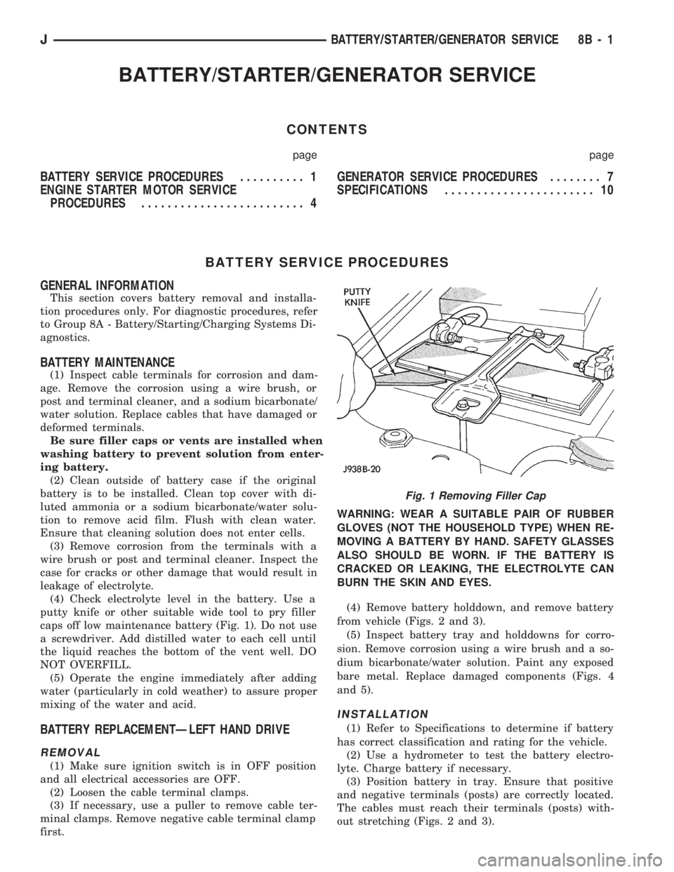
(4) Check electrolyte level in the battery. Use a
putty knife or other suitable wide tool to pry filler
caps off low maintenance battery (Fig. 1). Do not use
a screwdriver. Add distilled water to each cell until
the liquid reaches the bottom of the vent well. DO
NOT OVERFILL.
(5) Operate the engine immediately after adding
water (particularly in cold weather) to assure proper
mixing of the water and acid.
BATTERY REPLACEMENTÐLEFT HAND DRIVE
REMOVAL
(1) Make sure ignition switch is in OFF position
and all electrical accessories are OFF.
(2) Loosen the cable terminal clamps.
(3) If necessary, use a puller to remove cable ter-
minal clamps. Remove negative cable terminal clamp
first.WARNING: WEAR A SUITABLE PAIR OF RUBBER
GLOVES (NOT THE HOUSEHOLD TYPE) WHEN RE-
MOVING A BATTERY BY HAND. SAFETY GLASSES
ALSO SHOULD BE WORN. IF THE BATTERY IS
CRACKED OR LEAKING, THE ELECTROLYTE CAN
BURN THE SKIN AND EYES.
(4) Remove battery holddown, and remove battery
from vehicle (Figs. 2 and 3).
(5) Inspect battery tray and holddowns for corro-
sion. Remove corrosion using a wire brush and a so-
dium bicarbonate/water solution. Paint any exposed
bare metal. Replace damaged components (Figs. 4
and 5).
INSTALLATION
(1) Refer to Specifications to determine if battery
has correct classification and rating for the vehicle.
(2) Use a hydrometer to test the battery electro-
lyte. Charge battery if necessary.
(3) Position battery in tray. Ensure that positive
and negative terminals (posts) are correctly located.
The cables must reach their terminals (posts) with-
out stretching (Figs. 2 and 3).
Fig. 1 Removing Filler Cap
JBATTERY/STARTER/GENERATOR SERVICE 8B - 1
Page 296 of 1784
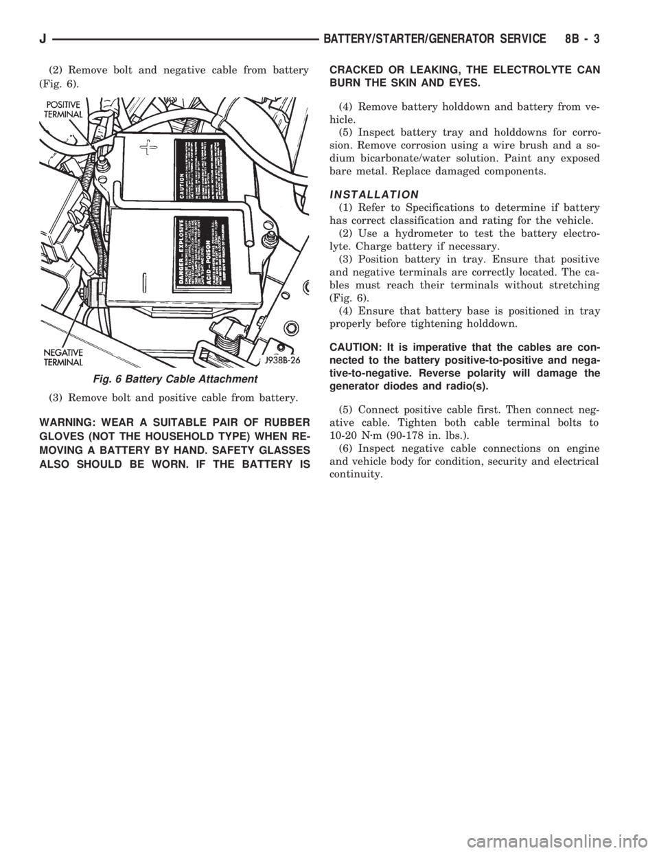
(2) Remove bolt and negative cable from battery
(Fig. 6).
(3) Remove bolt and positive cable from battery.
WARNING: WEAR A SUITABLE PAIR OF RUBBER
GLOVES (NOT THE HOUSEHOLD TYPE) WHEN RE-
MOVING A BATTERY BY HAND. SAFETY GLASSES
ALSO SHOULD BE WORN. IF THE BATTERY ISCRACKED OR LEAKING, THE ELECTROLYTE CAN
BURN THE SKIN AND EYES.
(4) Remove battery holddown and battery from ve-
hicle.
(5) Inspect battery tray and holddowns for corro-
sion. Remove corrosion using a wire brush and a so-
dium bicarbonate/water solution. Paint any exposed
bare metal. Replace damaged components.
INSTALLATION
(1) Refer to Specifications to determine if battery
has correct classification and rating for the vehicle.
(2) Use a hydrometer to test the battery electro-
lyte. Charge battery if necessary.
(3) Position battery in tray. Ensure that positive
and negative terminals are correctly located. The ca-
bles must reach their terminals without stretching
(Fig. 6).
(4) Ensure that battery base is positioned in tray
properly before tightening holddown.
CAUTION: It is imperative that the cables are con-
nected to the battery positive-to-positive and nega-
tive-to-negative. Reverse polarity will damage the
generator diodes and radio(s).
(5) Connect positive cable first. Then connect neg-
ative cable. Tighten both cable terminal bolts to
10-20 Nzm (90-178 in. lbs.).
(6) Inspect negative cable connections on engine
and vehicle body for condition, security and electrical
continuity.
Fig. 6 Battery Cable Attachment
JBATTERY/STARTER/GENERATOR SERVICE 8B - 3