1994 JEEP CHEROKEE warning
[x] Cancel search: warningPage 405 of 1784

(a) Remove 6 housing screws (Fig. 4).
(b) Slide housing toward steering wheel.
(18) Remove cover under column.
(19) If vehicle is equipped with a column shift, re-
move PRNDL cable clip (Fig. 5).
(20) Remove 2 nuts holding steering column
bracket to brake sled (Fig. 6).
(21) Remove 4 bolts holding steering column
bracket to column.
(22) Loosen column brace mounting nut at drivers
side kick panel. This will allow column to drop.(23) Push turn/hazard connector up and out of
steering column connector (Fig. 7).
(24) Pry up locking tabs of steering column connec-
tor and remove connector from column bracket.
(25) Tape connector to wires as shown (Fig. 8).
(26) Remove plastic harness cover by pulling it up
and over the weld nuts then open and slide the cover
off the harness (Fig. 9).
Fig. 4 Instrument Housing Removal/InstallationÐYJ
Fig. 5 PRNDL Cable Clip Removal/Installation
Fig. 6 Lower Steering Column
Fig. 7 Turn/Hazard Switch And Steering Column
Connectors
8J - 4 TURN SIGNALS AND HAZARD WARNING FLASHERJ
Page 406 of 1784
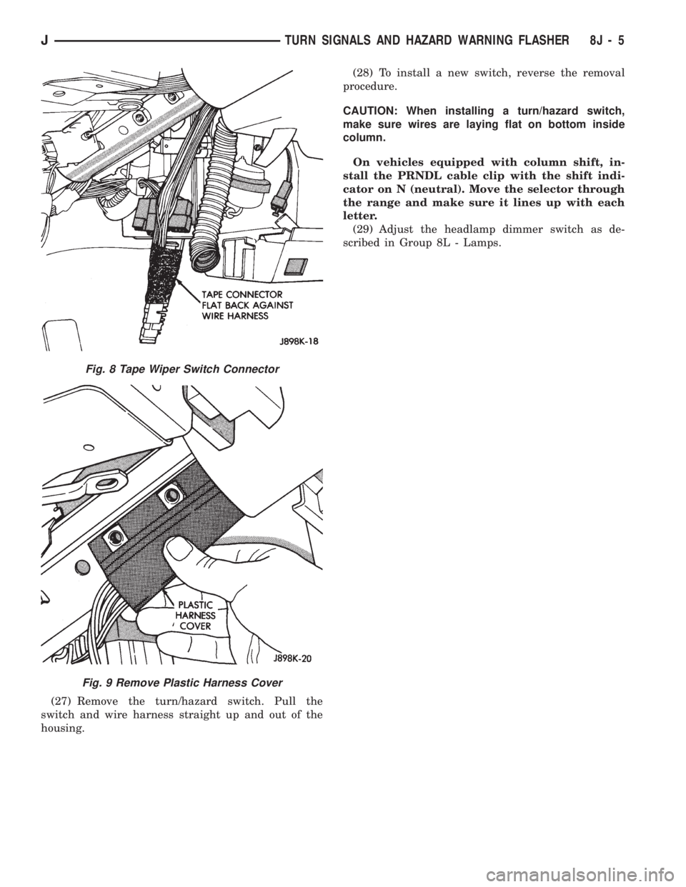
(27) Remove the turn/hazard switch. Pull the
switch and wire harness straight up and out of the
housing.(28) To install a new switch, reverse the removal
procedure.
CAUTION: When installing a turn/hazard switch,
make sure wires are laying flat on bottom inside
column.
On vehicles equipped with column shift, in-
stall the PRNDL cable clip with the shift indi-
cator on N (neutral). Move the selector through
the range and make sure it lines up with each
letter.
(29) Adjust the headlamp dimmer switch as de-
scribed in Group 8L - Lamps.
Fig. 8 Tape Wiper Switch Connector
Fig. 9 Remove Plastic Harness Cover
JTURN SIGNALS AND HAZARD WARNING FLASHER 8J - 5
Page 422 of 1784
WIPER CONTROL SWITCH REPLACEMENT
(1) Disconnect negative cable from battery.
(2) Remove horn button with a push and turn mo-
tion.
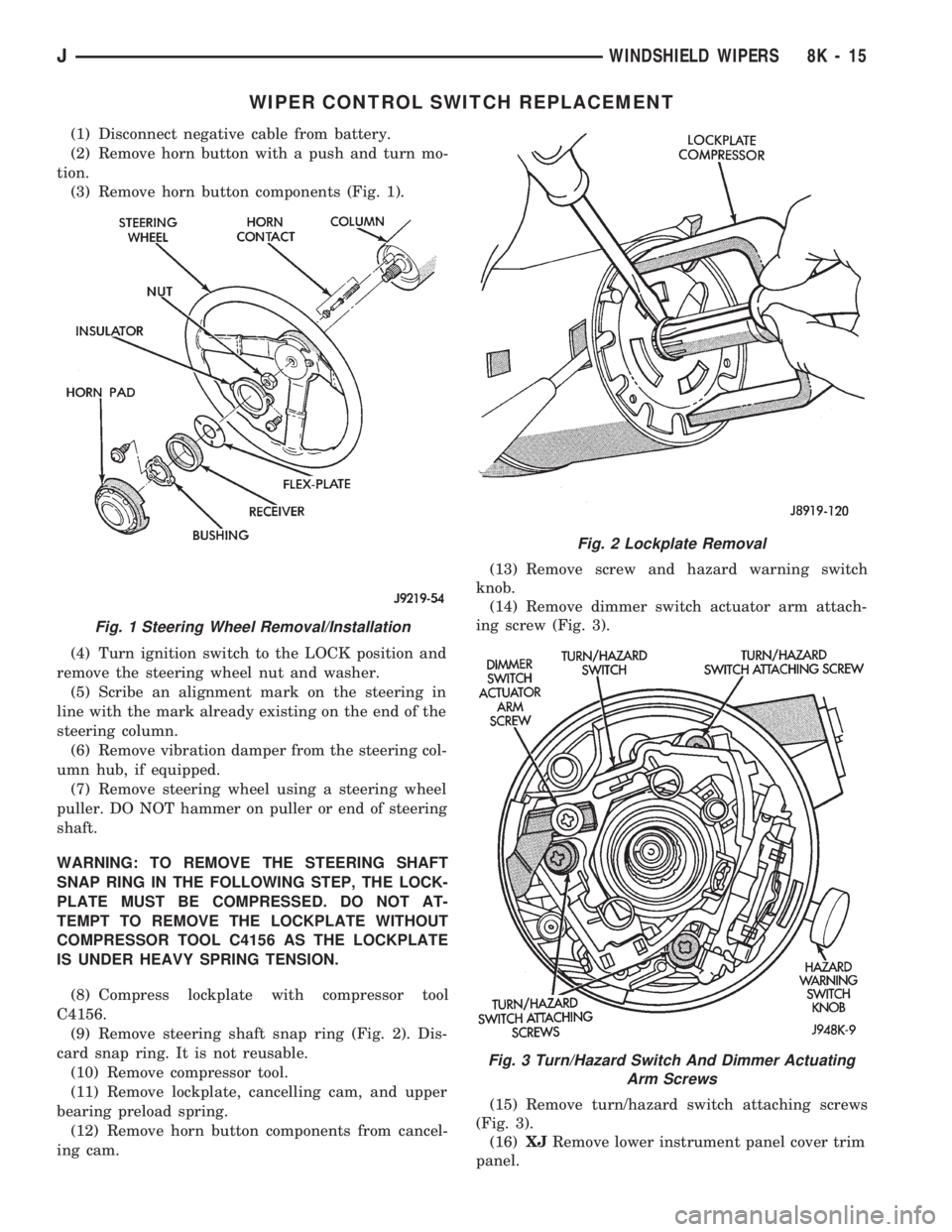
(3) Remove horn button components (Fig. 1).
(4) Turn ignition switch to the LOCK position and
remove the steering wheel nut and washer.
(5) Scribe an alignment mark on the steering in
line with the mark already existing on the end of the
steering column.
(6) Remove vibration damper from the steering col-
umn hub, if equipped.
(7) Remove steering wheel using a steering wheel
puller. DO NOT hammer on puller or end of steering
shaft.
WARNING: TO REMOVE THE STEERING SHAFT
SNAP RING IN THE FOLLOWING STEP, THE LOCK-
PLATE MUST BE COMPRESSED. DO NOT AT-
TEMPT TO REMOVE THE LOCKPLATE WITHOUT
COMPRESSOR TOOL C4156 AS THE LOCKPLATE
IS UNDER HEAVY SPRING TENSION.
(8) Compress lockplate with compressor tool
C4156.
(9) Remove steering shaft snap ring (Fig. 2). Dis-
card snap ring. It is not reusable.
(10) Remove compressor tool.
(11) Remove lockplate, cancelling cam, and upper
bearing preload spring.
(12) Remove horn button components from cancel-
ing cam.(13) Remove screw and hazard warning switch
knob.
(14) Remove dimmer switch actuator arm attach-
ing screw (Fig. 3).
(15) Remove turn/hazard switch attaching screws
(Fig. 3).
(16)XJRemove lower instrument panel cover trim
panel.
Fig. 1 Steering Wheel Removal/Installation
Fig. 2 Lockplate Removal
Fig. 3 Turn/Hazard Switch And Dimmer Actuating
Arm Screws
JWINDSHIELD WIPERS 8K - 15
Page 424 of 1784
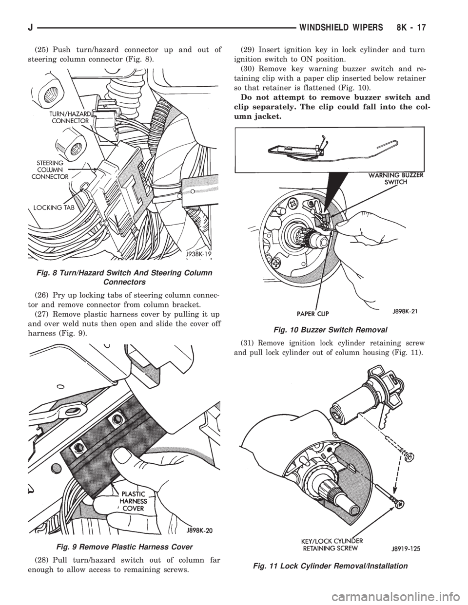
(25) Push turn/hazard connector up and out of
steering column connector (Fig. 8).
(26) Pry up locking tabs of steering column connec-
tor and remove connector from column bracket.
(27) Remove plastic harness cover by pulling it up
and over weld nuts then open and slide the cover off
harness (Fig. 9).
(28) Pull turn/hazard switch out of column far
enough to allow access to remaining screws.(29) Insert ignition key in lock cylinder and turn
ignition switch to ON position.
(30) Remove key warning buzzer switch and re-
taining clip with a paper clip inserted below retainer
so that retainer is flattened (Fig. 10).
Do not attempt to remove buzzer switch and
clip separately. The clip could fall into the col-
umn jacket.
(31) Remove ignition lock cylinder retaining screw
and pull lock cylinder out of column housing (Fig. 11).
Fig. 8 Turn/Hazard Switch And Steering Column
Connectors
Fig. 9 Remove Plastic Harness Cover
Fig. 10 Buzzer Switch Removal
Fig. 11 Lock Cylinder Removal/Installation
JWINDSHIELD WIPERS 8K - 17
Page 453 of 1784
A voltage drop of one-half the full amount, approx-
imately 6 volts, indicates a good grid or closed cir-
cuit.
A voltage drop of 12 volts at the centerline indi-
cates a break in the grid between the positive volt-
meter lead and the ground.
No voltage drop (0 volts) at the centerline indicates
a break in the grid between the centerline and the
voltage source or lead.
The exact location of the break can be pinpointed
by moving positive voltmeter lead to the left or right
along grid. An abrupt change in the voltage reading
will be noticed. The break is at that point in the
grid.
REAR WINDOW DEFOGGER GRID REPAIR
Locate the broken or open grid.
Use the grid repair kit (available as a service part)
by using the following procedure:
(1) Mark the location of the broken or open grid on
the exterior surface of the glass using a suitable
marking pencil.
(2) Lightly rub the area to be repaired (inside the
rear window) using fine steel wool. Clean the area
with alcohol.
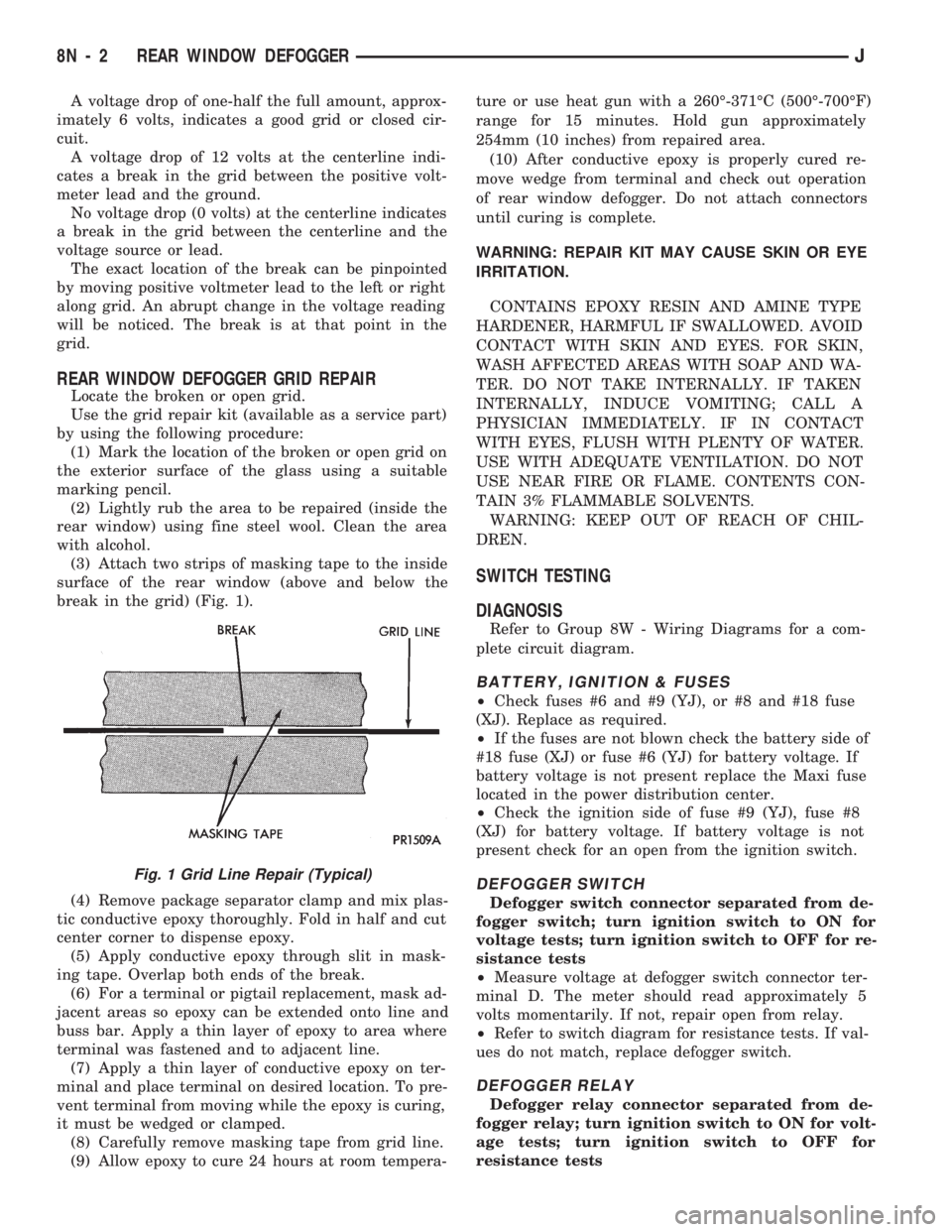
(3) Attach two strips of masking tape to the inside
surface of the rear window (above and below the
break in the grid) (Fig. 1).
(4) Remove package separator clamp and mix plas-
tic conductive epoxy thoroughly. Fold in half and cut
center corner to dispense epoxy.
(5) Apply conductive epoxy through slit in mask-
ing tape. Overlap both ends of the break.
(6) For a terminal or pigtail replacement, mask ad-
jacent areas so epoxy can be extended onto line and
buss bar. Apply a thin layer of epoxy to area where
terminal was fastened and to adjacent line.
(7) Apply a thin layer of conductive epoxy on ter-
minal and place terminal on desired location. To pre-
vent terminal from moving while the epoxy is curing,
it must be wedged or clamped.
(8) Carefully remove masking tape from grid line.
(9) Allow epoxy to cure 24 hours at room tempera-ture or use heat gun with a 260É-371ÉC (500É-700ÉF)
range for 15 minutes. Hold gun approximately
254mm (10 inches) from repaired area.
(10) After conductive epoxy is properly cured re-
move wedge from terminal and check out operation
of rear window defogger. Do not attach connectors
until curing is complete.
WARNING: REPAIR KIT MAY CAUSE SKIN OR EYE
IRRITATION.
CONTAINS EPOXY RESIN AND AMINE TYPE
HARDENER, HARMFUL IF SWALLOWED. AVOID
CONTACT WITH SKIN AND EYES. FOR SKIN,
WASH AFFECTED AREAS WITH SOAP AND WA-
TER. DO NOT TAKE INTERNALLY. IF TAKEN
INTERNALLY, INDUCE VOMITING; CALL A
PHYSICIAN IMMEDIATELY. IF IN CONTACT
WITH EYES, FLUSH WITH PLENTY OF WATER.
USE WITH ADEQUATE VENTILATION. DO NOT
USE NEAR FIRE OR FLAME. CONTENTS CON-
TAIN 3% FLAMMABLE SOLVENTS.
WARNING: KEEP OUT OF REACH OF CHIL-
DREN.
SWITCH TESTING
DIAGNOSIS
Refer to Group 8W - Wiring Diagrams for a com-
plete circuit diagram.
BATTERY, IGNITION & FUSES
²Check fuses #6 and #9 (YJ), or #8 and #18 fuse
(XJ). Replace as required.
²If the fuses are not blown check the battery side of
#18 fuse (XJ) or fuse #6 (YJ) for battery voltage. If
battery voltage is not present replace the Maxi fuse
located in the power distribution center.
²Check the ignition side of fuse #9 (YJ), fuse #8
(XJ) for battery voltage. If battery voltage is not
present check for an open from the ignition switch.
DEFOGGER SWITCH
Defogger switch connector separated from de-
fogger switch; turn ignition switch to ON for
voltage tests; turn ignition switch to OFF for re-
sistance tests
²Measure voltage at defogger switch connector ter-
minal D. The meter should read approximately 5
volts momentarily. If not, repair open from relay.
²Refer to switch diagram for resistance tests. If val-
ues do not match, replace defogger switch.
DEFOGGER RELAY
Defogger relay connector separated from de-
fogger relay; turn ignition switch to ON for volt-
age tests; turn ignition switch to OFF for
resistance tests
Fig. 1 Grid Line Repair (Typical)
8N - 2 REAR WINDOW DEFOGGERJ
Page 488 of 1784
CHIME/BUZZER WARNING SYSTEMS
CONTENTS
page page
GENERAL.............................. 1
IGNITION KEY WARNING SWITCH REPLACEMENT.4OPERATION/DIAGNOSIS.................. 1
GENERAL
The buzzer or optional chime module is mounted on
the left side of the fuse block (above and to the left of
the brake/clutch pedal). The buzzer or chime sounds
an audible warning tone in any of the following con-
ditions:
²Vehicle lights are ON when the ignition has been
switched OFF and the key is removed and then the
driver's door is opened (except YJ).²The key is in the ignition and the driver's door is
open (On some vehicles, the buzzer will not sound if
the ignition switch is in the ON position).
²The ignition is switched ON and the driver's seat
belt is not buckled. Buzzer will quit after 4 to 8 sec-
onds. Besides the buzzer, a seat belt indicator lamp
turns on as a reminder to fasten seat belt.
OPERATION/DIAGNOSIS
OPERATION
Battery voltage for module operation is supplied to
two pins. Voltage is always present at pin 7. Pin 1
receives voltage when the ignition switch is in the
ON or START position.
SEAT BELT WARNING
The seat belt warning system uses both visual and
audible signals. These consist of a buzzer that is part
of a combined seat belt and key warning buzzer and
a red light on the instrument panel.
The system will always illuminate the seat belt
warning lamp for four to eight seconds when the ig-
nition switch is turned to the ON position. Also, only
if the driver does not fasten his seat belt, the buzzer
will sound during the same time interval. Passenger
belts are not connected to the system.
A timed buzzer-relay is used to operate the system
for the time period. It has a time delay mechanism
and buzzer assembly. Only the driver's seat belt
buckle has a switch that is connected to the system.
KEY-IN-IGNITION WARNING
To sound the key-in-ignition warning, the following
must occur:
²the ignition key warning switch must be closed
²the driver's door jamb switch must be closed.
These conditions ground pin 6 of the module. These
switches are closed when the key is in the ignition
and the driver's door is open.On some vehicles the chime/buzzer will not
sound if the door is open and the key is in the
ON position.
LIGHTS-ON WARNING (EXCEPT YJ)
To sound the lights-on warning, the following must
occur:
²the headlamp switch must be closed
²the driver's door jamb switch must be closed.
These conditions ground pin 6 of the module. These
switches are closed when the headlamp switch is ON
and the driver's door is open.
DIAGNOSIS
If the buzzer/chime unit does not operate as de-
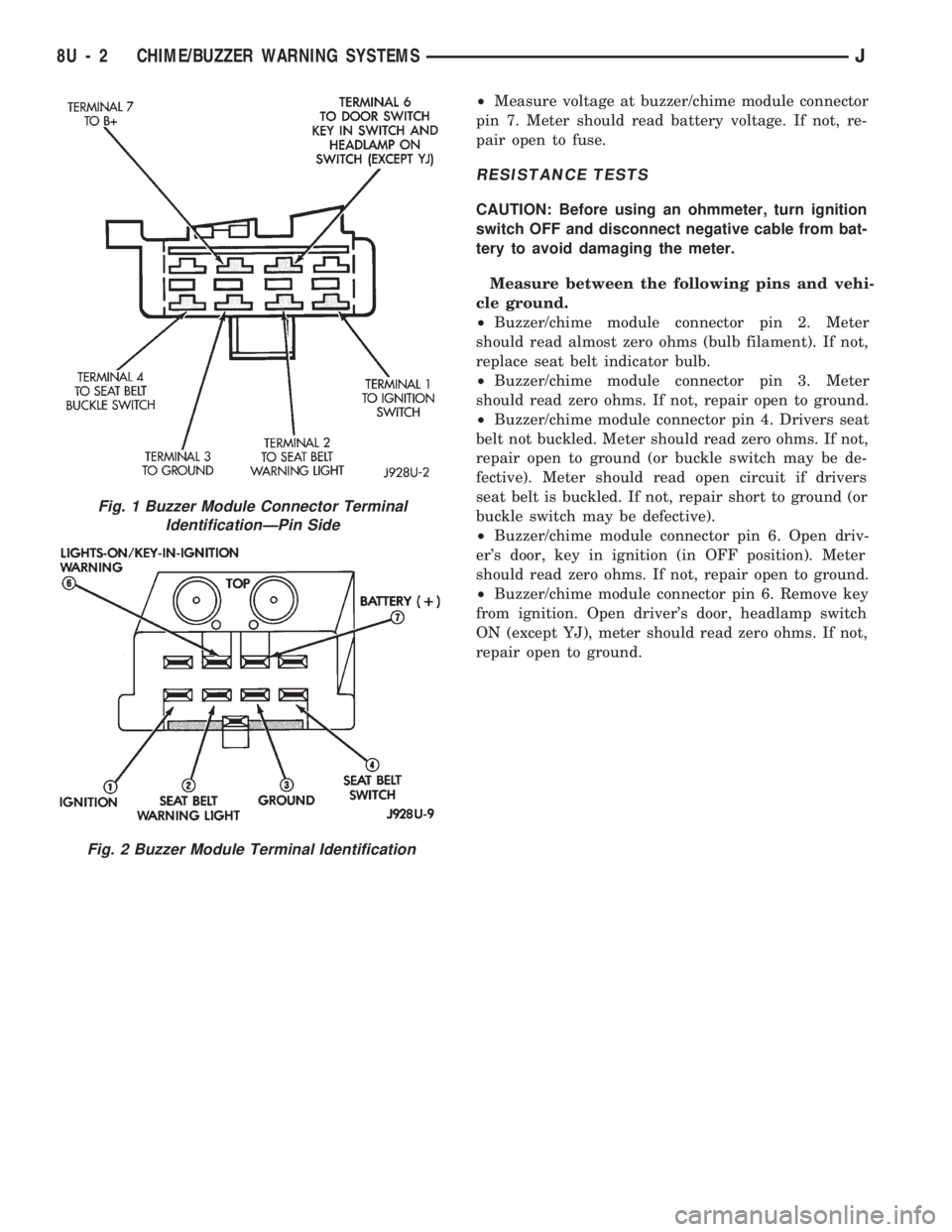
scribed, check the two fuses for pins 1 and 7 (Figs. 1
and 2) and replace as required. If the fuses are not
defective, perform the following tests to determine if
the problem is in the module or in the wiring. Using
a flat head screwdriver, release the locking plastic
clip while carefully pulling out the module. Plug in a
known good module and check its operation. If the
problem is not corrected by replacing the module, re-
move the module and continue as follows:
VOLTAGE TESTS
Ignition in ON position, measure between the
following pins and vehicle ground.
²Measure voltage at buzzer/chime module connector
pin 1. Meter should read battery voltage. If not, re-
pair open to ignition switch.
Turn ignition OFF and remove the key from the ig-
nition.
JCHIME/BUZZER WARNING SYSTEMS 8U - 1
Page 489 of 1784
²Measure voltage at buzzer/chime module connector
pin 7. Meter should read battery voltage. If not, re-
pair open to fuse.
RESISTANCE TESTS
CAUTION: Before using an ohmmeter, turn ignition
switch OFF and disconnect negative cable from bat-
tery to avoid damaging the meter.
Measure between the following pins and vehi-
cle ground.
²Buzzer/chime module connector pin 2. Meter
should read almost zero ohms (bulb filament). If not,
replace seat belt indicator bulb.
²Buzzer/chime module connector pin 3. Meter
should read zero ohms. If not, repair open to ground.
²Buzzer/chime module connector pin 4. Drivers seat
belt not buckled. Meter should read zero ohms. If not,
repair open to ground (or buckle switch may be de-
fective). Meter should read open circuit if drivers
seat belt is buckled. If not, repair short to ground (or
buckle switch may be defective).
²Buzzer/chime module connector pin 6. Open driv-
er's door, key in ignition (in OFF position). Meter
should read zero ohms. If not, repair open to ground.
²Buzzer/chime module connector pin 6. Remove key
from ignition. Open driver's door, headlamp switch
ON (except YJ), meter should read zero ohms. If not,
repair open to ground.
Fig. 2 Buzzer Module Terminal Identification
Fig. 1 Buzzer Module Connector Terminal
IdentificationÐPin Side
8U - 2 CHIME/BUZZER WARNING SYSTEMSJ
Page 490 of 1784
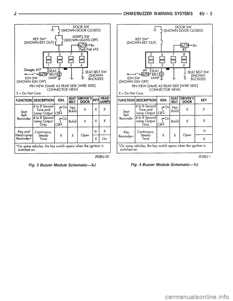
Fig. 4 Buzzer Module SchematicÐYJFig. 3 Buzzer Module SchematicÐXJ
JCHIME/BUZZER WARNING SYSTEMS 8U - 3