1994 JEEP CHEROKEE warning
[x] Cancel search: warningPage 491 of 1784
IGNITION KEY WARNING SWITCH REPLACEMENT
(1) Disconnect negative cable from battery.
(2) Remove horn button with a push and turn mo-
tion.
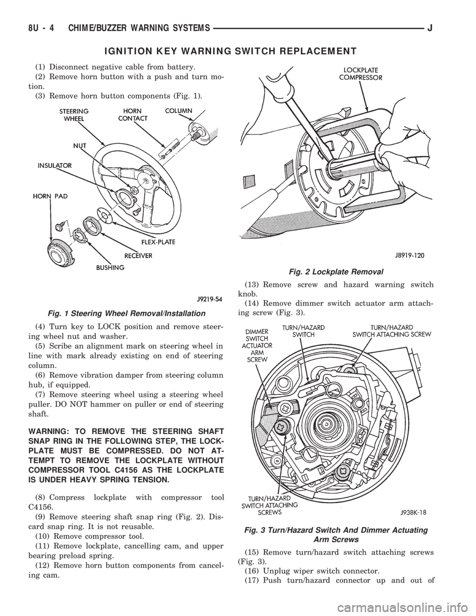
(3) Remove horn button components (Fig. 1).
(4) Turn key to LOCK position and remove steer-
ing wheel nut and washer.
(5) Scribe an alignment mark on steering wheel in
line with mark already existing on end of steering
column.
(6) Remove vibration damper from steering column
hub, if equipped.
(7) Remove steering wheel using a steering wheel
puller. DO NOT hammer on puller or end of steering
shaft.
WARNING: TO REMOVE THE STEERING SHAFT
SNAP RING IN THE FOLLOWING STEP, THE LOCK-
PLATE MUST BE COMPRESSED. DO NOT AT-
TEMPT TO REMOVE THE LOCKPLATE WITHOUT
COMPRESSOR TOOL C4156 AS THE LOCKPLATE
IS UNDER HEAVY SPRING TENSION.
(8) Compress lockplate with compressor tool
C4156.
(9) Remove steering shaft snap ring (Fig. 2). Dis-
card snap ring. It is not reusable.
(10) Remove compressor tool.
(11) Remove lockplate, cancelling cam, and upper
bearing preload spring.
(12) Remove horn button components from cancel-
ing cam.(13) Remove screw and hazard warning switch
knob.
(14) Remove dimmer switch actuator arm attach-
ing screw (Fig. 3).
(15) Remove turn/hazard switch attaching screws
(Fig. 3).
(16) Unplug wiper switch connector.
(17) Push turn/hazard connector up and out of
Fig. 1 Steering Wheel Removal/Installation
Fig. 2 Lockplate Removal
Fig. 3 Turn/Hazard Switch And Dimmer Actuating
Arm Screws
8U - 4 CHIME/BUZZER WARNING SYSTEMSJ
Page 492 of 1784
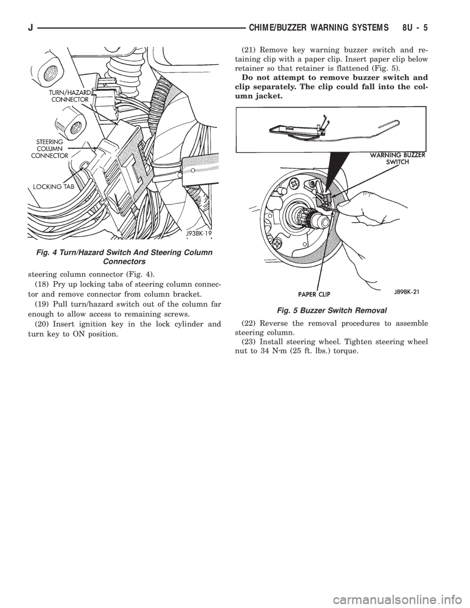
steering column connector (Fig. 4).
(18) Pry up locking tabs of steering column connec-
tor and remove connector from column bracket.
(19) Pull turn/hazard switch out of the column far
enough to allow access to remaining screws.
(20) Insert ignition key in the lock cylinder and
turn key to ON position.(21) Remove key warning buzzer switch and re-
taining clip with a paper clip. Insert paper clip below
retainer so that retainer is flattened (Fig. 5).
Do not attempt to remove buzzer switch and
clip separately. The clip could fall into the col-
umn jacket.
(22) Reverse the removal procedures to assemble
steering column.
(23) Install steering wheel. Tighten steering wheel
nut to 34 Nzm (25 ft. lbs.) torque.
Fig. 4 Turn/Hazard Switch And Steering Column
Connectors
Fig. 5 Buzzer Switch Removal
JCHIME/BUZZER WARNING SYSTEMS 8U - 5
Page 566 of 1784
WIRING DIAGRAMS YJ
ALPHABETICAL INDEX
Wiring Diagram Name Sheet Number
ABS Accelerator Sensor........................59
ABS Control Module.....................57, 58, 59
ABS Control Module Connector...................60
ABS Motor Pump Relay........................57
ABS Power Relay............................57
A/C Blower Switch............................50
A/C Compressor.............................49
A/C Low Pressure Switch.......................49
A/C Relay.................................49
A/C Thermostat..............................50
Accessory Illumination.........................32
Air Conditioning System (4.0L).................49, 50
A/C Blower Switch..........................50
A/C Compressor............................49
A/C Low Pressure Switch.....................49
A/C Relay................................49
A/C Thermostat............................50
Field Jumper..............................50
Powertrain Control Module.....................49
Anti-Lock Brake System (TEVES).............57, 58, 59
ABS Accelerator Sensor.......................59
ABS Control Module....................57, 58, 59
ABS Motor Pump Relay.......................57
ABS Power Relay...........................57
Brake Pedal Travel Sensor.....................57
Data Link Connector.........................57
Diode..................................58
Hydraulic Actuation Unit......................58
Left Front Wheel Sensor......................59
Left Rear Wheel Sensor.......................59
Power Distribution Center.....................57
Pump Motor..............................57
Pump Motor Sensor.........................57
Right Front Wheel Sensor.....................59
Right Rear Wheel Sensor......................59
Automatic Shut-Down Relay...................11, 17
Back-Up Lamps...........................51, 52
Back-Up Lamp Switch..........................7
Battery................................1,3,5
Blower Motor...............................47
Blower Resistor.............................47
Blower Switch..............................47
Body Harness Connector........................36
Brake Pedal Travel Sensor.......................57
Brake Warning Switch..........................9
Bulkhead Connector........................65, 66
Buzzer Module..............................36
Camshaft Position Sensor....................12, 18
Center High Mounted Stop Lamp..................52
Charging System 2.5L Engine...................3,4
Battery..................................3
Generator.................................3
Power Distribution Center......................4Wiring Diagram Name Sheet Number
Charging System 4.0L Engine...................5,6
Battery..................................5
Generator.................................5
Power Distribution Center......................6
Cigar Lighter...............................24
Circuit Breakers
Headlamp Switch.........................1,29
#11 (W/Wiper).....................2,10,38,39
Clock....................................45
Cluster Connector............................41
Crankshaft Position Sensor...................12, 18
Data Link Connector.....................13, 19, 57
Daytime Running Lamp Module...................28
Dimmer Switch............................1,29
Dome and Courtesy Lamps......................35
Dome Lamp..............................35
Left Courtesy Lamp.........................35
Left Front Door Jamb Switch...................35
Right Courtesy Lamp........................35
Right Front Door Jamb Switch..................35
Dome Lamp................................35
Electrically Tuned Radio with Clock.................45
Electrical Schematic of Cluster....................42
Electrical Schematic of Gauge Package..............44
Electronic Speedometer.........................42
Electronic Tachometer..........................42
Engine Coolant Temp Gauge.....................44
Engine Coolant Temperature Sensor..............15, 21
Engine Oil Pressure and Temperature System..........23
Engine Coolant Temperature Sending Unit...........23
Engine Oil Pressure Sending Unit................23
Engine Oil Pressure Gauge......................44
Engine Starter System........................2,7
Back-Up Lamp Switch........................7
Engine Starter Motor.........................7
Engine Starter Relay..........................7
Park/Neutral Position Switch....................7
Engine Wiring Connector (16 Way).................69
4-WD Command Trac Switch......................8
Field Jumper...............................50
Fog Lamp Relays............................30
Fog Lamp Switch............................30
Front End Lighting.........................25, 26
Left Fog Lamp.............................25
Left Headlamp.............................25
Left Park and Turn Signal Lamp.................25
Left Side Marker Lamp.......................25
Right Fog Lamp............................26
Right Headlamp............................26
Right Park and Turn Signal Lamp................26
Right Side Marker Lamp......................26
Front End Lighting (Canada)...................27, 28
Daytime Running Lamp Module.................28
JWIRING DIAGRAMS 8W - 73
Page 567 of 1784
Wiring Diagram Name Sheet Number
Left Fog Lamp.............................27
Left Headlamp.............................27
Left Park and Turn Signal Lamp.................27
Left Side Marker Lamp.......................27
Right Fog Lamp............................28
Right Headlamp............................28
Right Park and Turn Signal Lamp................28
Right Side Marker Lamp......................28
Fuel Gauge................................44
Fuel Injection Ignition System
2.5L Engine.................11, 12, 13, 14, 15, 16
Automatic Shut Down Relay....................11
Camshaft Position Sensor.....................12
Crankshaft Position Sensor.....................12
Data Link Connector.........................13
Engine Coolant Temperature Sensor...............15
Fuel Injectors.............................14
Fuel Pump Relay...........................11
Heated Oxygen Sensor.......................11
Idle Air Control Motor........................14
Ignition Coil..............................13
Intake Air Temperature Sensor..................15
MAP Sensor..............................15
Power Steering Switch.......................14
Powertrain Control Module (PCM) . . .11, 12, 13, 14, 15, 16
Throttle Position (Sensor).....................15
Vehicle Speed Sensor........................12
Fuel Injection Ignition System
4.0L Engine.................17, 18, 19, 20, 21, 22
Automatic Shut Down Relay....................17
Camshaft Position Sensor.....................18
Crankshaft Position Sensor.....................18
Data Link Connector.........................19
Engine Coolant Temperature Sensor...............21
Fuel Injectors.............................20
Fuel Pump Relay...........................17
Heated Oxygen Sensor.......................17
Idle Air Control Motor........................20
Ignition Coil..............................19
Intake Air Temperature Sensor..................21
MAP Sensor..............................21
Powertrain Control Module (PCM) . . .17, 18, 19, 20, 21, 22
Throttle Position (Sensor).....................21
Vehicle Speed Sensor........................18
Fuel Injectors............................14, 20
Fuel Pump Relay..........................11, 17
Fuel Tank System............................55
Fuel Tank Sending Unit.........................55
Fuse Application Chart........................1,2
Fuses
1 .................................2,10,37
3 ..............................1,30,34,36
4 .................................2,10,34
5 ..............................2,10,13,19
6 .................................1,30,53
7 ..............................2,10,24,46
8 ...................................1,29
9 .................................2,10,36Wiring Diagram Name Sheet Number
10 ...................................1,31
11 .............................2,10,38,39
12 ...........................2,10,47,48,50
F13 ..................................2,58
F15 ..............................2,4,6,33
F16 ............................2,4,6,8,35
Fuse Panel..............................61, 62
Gauge Package Connector.......................43
Gauges
Electronic Speedometer.......................42
Electronic Tachometer........................42
Engine Coolant Temperature Gauge...............44
Engine Oil Pressure Gauge.....................44
Fuel Gauge...............................44
Voltmeter................................44
Generator................................3,5
Hazard Signal Flasher..........................34
Headlamps.........................25, 26, 27, 28
Headlamp Switch........................1,29,30
Dimmer Switch............................29
Headlamp Switch...........................29
Heated Oxygen Sensor......................11, 17
Heated Rear Window Relay......................54
Heated Rear Window Switch.....................53
Heated Rear Window System..................53, 54
Heated Rear Window Grid.....................53
Heated Rear Window Relay....................54
Heated Rear Window Switch....................53
Timer..................................54
Heater Control Panel Illumination..................32
Heater System..............................47
Blower Motor.............................47
Blower Resistor............................47
Blower Switch.............................47
Heater/Off Switch...........................47
Horn.....................................33
Horn Brush/Slip Ring........................33
Horn Relay...............................33
Horn Switch..............................33
Hydraulic Actuation Unit........................58
Idle Air Control Motor.......................14, 20
Ignition Coil.............................13, 19
Ignition Key Warning Switch.....................36
Ignition Switch..........................2,9,10
Instrument Panel Illumination Lamps................32
Intake Air Temperature Sensor.................15, 21
Intermittent Wiper Module.......................40
Intermittent Wiper System....................39, 40
Intermittent Wiper Module.....................40
Park Switch..............................39
Washer Pump.............................39
Wiper Motor..............................39
Wiper/Washer Switch........................40
W/Wiper Circuit Breaker (5.3 Amp)...............39
Lamps
Center High Mounted Stop Lamps................52
Dome Lamp..............................35
Instrument Panel Illumination Lamp...............32
8W - 74 WIRING DIAGRAMSJ
Page 568 of 1784
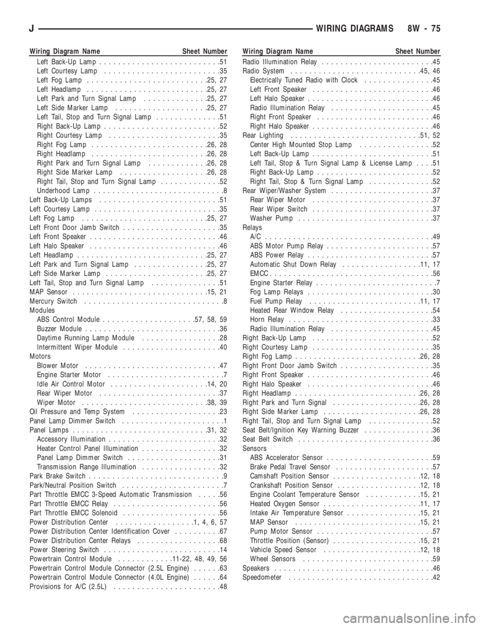
Wiring Diagram Name Sheet Number
Left Back-Up Lamp..........................51
Left Courtesy Lamp.........................35
Left Fog Lamp..........................25, 27
Left Headlamp..........................25, 27
Left Park and Turn Signal Lamp..............25, 27
Left Side Marker Lamp....................25, 27
Left Tail, Stop and Turn Signal Lamp..............51
Right Back-Up Lamp.........................52
Right Courtesy Lamp........................35
Right Fog Lamp.........................26, 28
Right Headlamp.........................26, 28
Right Park and Turn Signal Lamp.............26, 28
Right Side Marker Lamp...................26, 28
Right Tail, Stop and Turn Signal Lamp.............52
Underhood Lamp............................8
Left Back-Up Lamps..........................51
Left Courtesy Lamp...........................35
Left Fog Lamp...........................25, 27
Left Front Door Jamb Switch.....................35
Left Front Speaker............................46
Left Halo Speaker............................46
Left Headlamp............................25, 27
Left Park and Turn Signal Lamp................25, 27
Left Side Marker Lamp......................25, 27
Left Tail, Stop and Turn Signal Lamp...............51
MAP Sensor.............................15, 21
Mercury Switch..............................8
Modules
ABS Control Module....................57, 58, 59
Buzzer Module.............................36
Daytime Running Lamp Module.................28
Intermittent Wiper Module.....................40
Motors
Blower Motor.............................47
Engine Starter Motor.........................7
Idle Air Control Motor.....................14, 20
Rear Wiper Motor..........................37
Wiper Motor...........................38, 39
Oil Pressure and Temp System...................23
Panel Lamp Dimmer Switch......................1
Panel Lamps.............................31, 32
Accessory Illumination........................32
Heater Control Panel Illumination.................32
Panel Lamp Dimmer Switch....................31
Transmission Range Illumination.................32
Park Brake Switch.............................9
Park/Neutral Position Switch......................7
Part Throttle EMCC 3-Speed Automatic Transmission.....56
Part Throttle EMCC Relay.......................56
Part Throttle EMCC Solenoid.....................56
Power Distribution Center.................1,4,6,57
Power Distribution Center Identification Cover..........67
Power Distribution Center Relays..................68
Power Steering Switch.........................14
Powertrain Control Module............11-22, 48, 49, 56
Powertrain Control Module Connector (2.5L Engine)......63
Powertrain Control Module Connector (4.0L Engine)......64
Provisions for A/C (2.5L).......................48Wiring Diagram Name Sheet Number
Radio Illumination Relay........................45
Radio System............................45, 46
Electrically Tuned Radio with Clock...............45
Left Front Speaker..........................46
Left Halo Speaker...........................46
Radio Illumination Relay......................45
Right Front Speaker.........................46
Right Halo Speaker..........................46
Rear Lighting............................51, 52
Center High Mounted Stop Lamp................52
Left Back-Up Lamp..........................51
Left Tail, Stop & Turn Signal Lamp & License Lamp....51
Right Back-Up Lamp.........................52
Right Tail, Stop & Turn Signal Lamp..............52
Rear Wiper/Washer System......................37
Rear Wiper Motor..........................37
Rear Wiper Switch..........................37
Washer Pump.............................37
Relays
A/C ....................................49
ABS Motor Pump Relay.......................57
ABS Power Relay...........................57
Automatic Shut Down Relay.................11, 17
EMCC...................................56
Engine Starter Relay..........................7
Fog Lamp Relays...........................30
Fuel Pump Relay........................11, 17
Heated Rear Window Relay....................54
Horn Relay...............................33
Radio Illumination Relay......................45
Right Back-Up Lamp..........................52
Right Courtesy Lamp..........................35
Right Fog Lamp...........................26, 28
Right Front Door Jamb Switch....................35
Right Front Speaker...........................46
Right Halo Speaker...........................46
Right Headlamp...........................26, 28
Right Park and Turn Signal...................26, 28
Right Side Marker Lamp.....................26, 28
Right Tail, Stop and Turn Signal Lamp..............52
Seat Belt/Ignition Key Warning Buzzer...............36
Seat Belt Switch.............................36
Sensors
ABS Accelerator Sensor.......................59
Brake Pedal Travel Sensor.....................57
Camshaft Position Sensor...................12, 18
Crankshaft Position Sensor..................12, 18
Engine Coolant Temperature Sensor............15, 21
Heated Oxygen Sensor.....................11, 17
Intake Air Temperature Sensor................15, 21
MAP Sensor...........................15, 21
Pump Motor Sensor.........................57
Throttle Position (Sensor)...................15, 21
Vehicle Speed Sensor.....................12, 18
Wheel Sensors............................59
Speakers..................................46
Speedometer...............................42
JWIRING DIAGRAMS 8W - 75
Page 569 of 1784
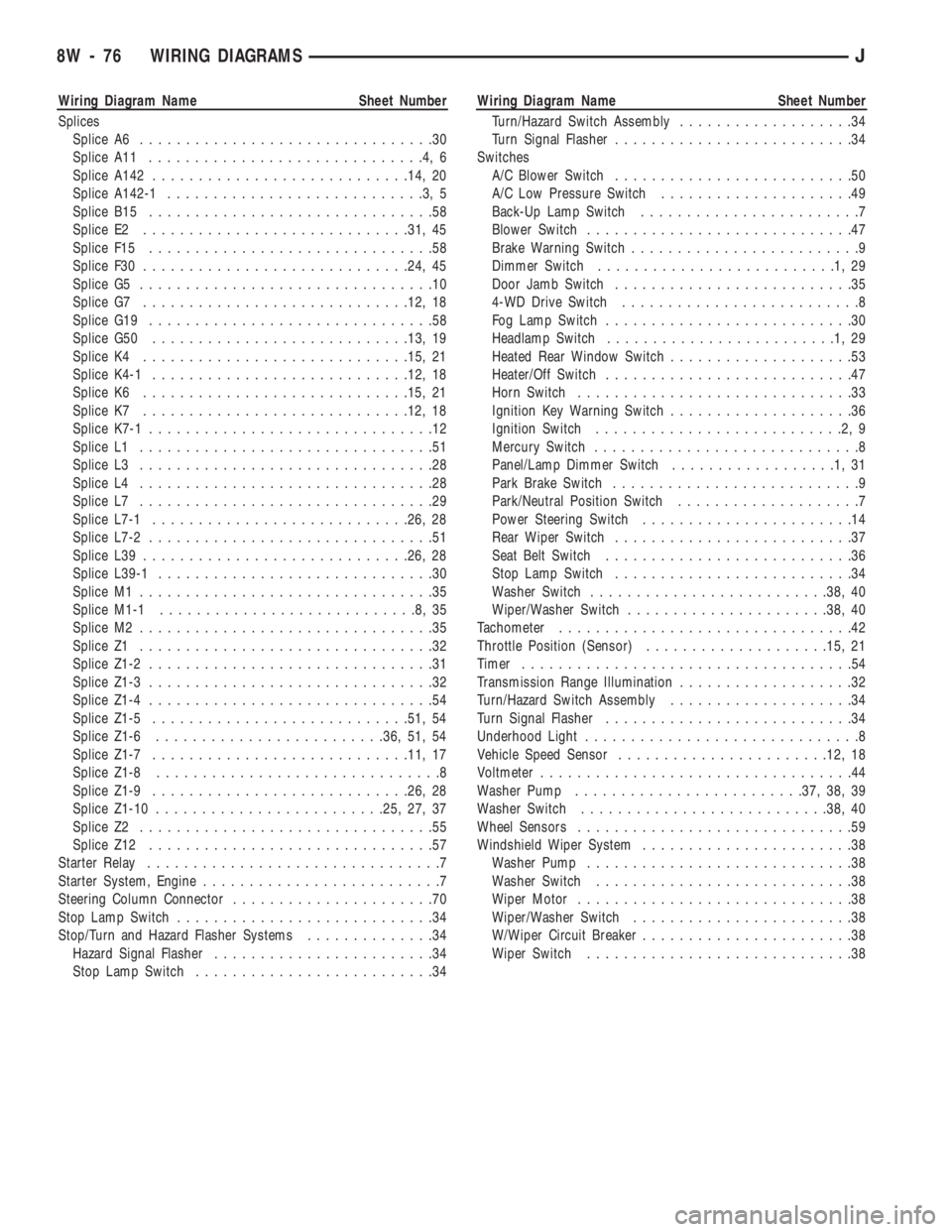
Wiring Diagram Name Sheet Number
Splices
Splice A6................................30
Splice A11..............................4,6
Splice A142............................14, 20
Splice A142-1............................3,5
Splice B15...............................58
Splice E2.............................31, 45
Splice F15...............................58
Splice F30.............................24, 45
Splice G5................................10
Splice G7.............................12, 18
Splice G19...............................58
Splice G50............................13, 19
Splice K4.............................15, 21
Splice K4-1............................12, 18
Splice K6.............................15, 21
Splice K7.............................12, 18
Splice K7-1...............................12
Splice L1................................51
Splice L3................................28
Splice L4................................28
Splice L7................................29
Splice L7-1............................26, 28
Splice L7-2...............................51
Splice L39.............................26, 28
Splice L39-1..............................30
Splice M1................................35
Splice M1-1............................8,35
Splice M2................................35
Splice Z1................................32
Splice Z1-2...............................31
Splice Z1-3...............................32
Splice Z1-4...............................54
Splice Z1-5............................51, 54
Splice Z1-6.........................36, 51, 54
Splice Z1-7............................11, 17
Splice Z1-8...............................8
Splice Z1-9............................26, 28
Splice Z1-10.........................25, 27, 37
Splice Z2................................55
Splice Z12...............................57
Starter Relay................................7
Starter System, Engine..........................7
Steering Column Connector......................70
Stop Lamp Switch............................34
Stop/Turn and Hazard Flasher Systems..............34
Hazard Signal Flasher........................34
Stop Lamp Switch..........................34Wiring Diagram Name Sheet Number
Turn/Hazard Switch Assembly...................34
Turn Signal Flasher..........................34
Switches
A/C Blower Switch..........................50
A/C Low Pressure Switch.....................49
Back-Up Lamp Switch........................7
Blower Switch.............................47
Brake Warning Switch.........................9
Dimmer Switch..........................1,29
Door Jamb Switch..........................35
4-WD Drive Switch..........................8
Fog Lamp Switch...........................30
Headlamp Switch.........................1,29
Heated Rear Window Switch....................53
Heater/Off Switch...........................47
Horn Switch..............................33
Ignition Key Warning Switch....................36
Ignition Switch...........................2,9
Mercury Switch.............................8
Panel/Lamp Dimmer Switch..................1,31
Park Brake Switch...........................9
Park/Neutral Position Switch....................7
Power Steering Switch.......................14
Rear Wiper Switch..........................37
Seat Belt Switch...........................36
Stop Lamp Switch..........................34
Washer Switch..........................38, 40
Wiper/Washer Switch......................38, 40
Tachometer................................42
Throttle Position (Sensor)....................15, 21
Timer....................................54
Transmission Range Illumination...................32
Turn/Hazard Switch Assembly....................34
Turn Signal Flasher...........................34
Underhood Light..............................8
Vehicle Speed Sensor.......................12, 18
Voltmeter..................................44
Washer Pump.........................37, 38, 39
Washer Switch...........................38, 40
Wheel Sensors..............................59
Windshield Wiper System.......................38
Washer Pump.............................38
Washer Switch............................38
Wiper Motor..............................38
Wiper/Washer Switch........................38
W/Wiper Circuit Breaker.......................38
Wiper Switch.............................38
8W - 76 WIRING DIAGRAMSJ
Page 642 of 1784
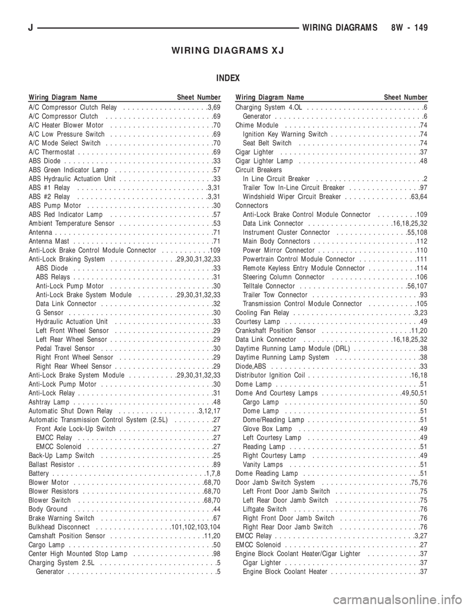
WIRING DIAGRAMS XJ
INDEX
Wiring Diagram Name Sheet Number
A/C Compressor Clutch Relay...................3,69
A/C Compressor Clutch........................69
A/C Heater Blower Motor.......................70
A/C Low Pressure Switch.......................69
A/C Mode Select Switch........................70
A/C Thermostat..............................69
ABS Diode.................................33
ABS Green Indicator Lamp......................57
ABS Hydraulic Actuation Unit.....................33
ABS #1 Relay.............................3,31
ABS #2 Relay.............................3,31
ABS Pump Motor............................30
ABS Red Indicator Lamp.......................57
Ambient Temperature Sensor.....................53
Antenna...................................71
Antenna Mast...............................71
Anti-Lock Brake Control Module Connector...........109
Anti-Lock Braking System...............29,30,31,32,33
ABS Diode...............................33
ABS Relays...............................31
Anti-Lock Pump Motor.......................30
Anti-Lock Brake System Module.........29,30,31,32,33
Data Link Connector.........................32
G Sensor................................30
Hydraulic Actuation Unit......................33
Left Front Wheel Sensor......................29
Left Rear Wheel Sensor.......................29
Pedal Travel Sensor.........................30
Right Front Wheel Sensor.....................29
Right Rear Wheel Sensor......................29
Anti-Lock Brake System Module...........29,30,31,32,33
Anti-Lock Pump Motor.........................30
Anti-Lock Relay..............................31
Ashtray Lamp...............................48
Automatic Shut Down Relay..................3,12,17
Automatic Transmission Control System (2.5L).........27
Front Axle Lock-Up Switch.....................27
EMCC Relay..............................27
EMCC Solenoid............................27
Back-Up Lamp Switch.........................25
Ballast Resistor..............................89
Battery..................................1,7,8
Blower Motor.............................68,70
Blower Resistors...........................68,70
Blower Switch............................68,70
Body Ground...............................44
Brake Warning Switch.........................67
Bulkhead Disconnect.................101,102,103,104
Camshaft Position Sensor.....................11,20
Cargo Lamp................................50
Center High Mounted Stop Lamp..................98
Charging System 2.5L..........................5
Generator.................................5Wiring Diagram Name Sheet Number
Charging System 4.OL..........................6
Generator.................................6
Chime Module..............................74
Ignition Key Warning Switch....................74
Seat Belt Switch...........................74
Cigar Lighter...............................37
Cigar Lighter Lamp...........................48
Circuit Breakers
In Line Circuit Breaker........................2
Trailer Tow In-Line Circuit Breaker................97
Windshield Wiper Circuit Breaker...............63,64
Connectors
Anti-Lock Brake Control Module Connector.........109
Data Link Connector...................16,18,25,32
Instrument Cluster Connector................55,108
Main Body Connectors.......................112
Power Mirror Connector......................110
Powertrain Control Module Connector.............111
Remote Keyless Entry Module Connector...........114
Steering Column Connector...................106
Telltale Connector........................56,107
Trailer Tow Connector........................93
Transmission Control Module Connector...........105
Cooling Fan Relay...........................3,23
Courtesy Lamp..............................49
Crankshaft Position Sensor....................11,20
Data Link Connector....................16,18,25,32
Daytime Running Lamp Module (DRL)...............38
Daytime Running Lamp System...................38
Diode,ABS.................................33
Distributor Ignition Coil.......................16,18
Dome Lamp................................51
Dome And Courtesy Lamps..................49,50,51
Cargo Lamp..............................50
Dome Lamp..............................51
Dome/Reading Lamp.........................51
Glove Box Lamp...........................49
Left Courtesy Lamp.........................49
Reading Lamp.............................51
Right Courtesy Lamp........................49
Vanity Lamps.............................51
Dome Reading Lamp..........................51
Door Jamb Switch System....................75,76
Left Front Door Jamb Switch...................75
Left Rear Door Jamb Switch...................75
Liftgate Switch............................76
Right Front Door Jamb Switch..................76
Right Rear Door Jamb Switch..................76
EMCC Relay...............................3,27
EMCC Solenoid..............................27
Engine Block Coolant Heater/Cigar Lighter............37
Cigar Lighter..............................37
Engine Block Coolant Heater....................37
JWIRING DIAGRAMS 8W - 149
Page 644 of 1784
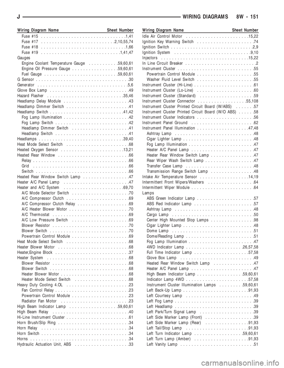
Wiring Diagram Name Sheet Number
Fuse #15...............................1,41
Fuse #17...........................2,10,55,74
Fuse #18...............................1,66
Fuse #19.............................1,41,47
Gauges
Engine Coolant Temperature Gauge...........59,60,61
Engine Oil Pressure Gauge.................59,60,61
Fuel Gauge...........................59,60,61
G Sensor..................................30
Generator.................................5,6
Glove Box Lamp.............................49
Hazard Flasher............................35,46
Headlamp Delay Module........................43
Headlamp Dimmer Switch.......................41
Headlamp Switch...........................41,42
Fog Lamp Illumination........................42
Fog Lamp Switch...........................42
Headlamp Dimmer Switch.....................41
Headlamp Switch...........................41
Headlamps...............................39,40
Heat Mode Select Switch.......................68
Heated Oxygen Sensor.......................13,21
Heated Rear Window..........................66
Relay...................................66
Grid...................................66
Switch..................................66
Heated Rear Window Switch Lamp.................47
Heater A/C Panel Lamp........................47
Heater and A/C System......................69,70
A/C Mode Selector Switch.....................70
A/C Compressor Clutch.......................69
A/C Compressor Clutch Relay...................69
A/C Heater Blower Motor......................70
A/C Thermostat............................69
A/C Low Pressure Switch.....................69
Blower Resistor............................70
Blower Switch.............................70
Powertrain Control Module.....................69
Heat Mode Select Switch.......................68
Heater Blower Motor..........................68
Heater,Engine Block...........................37
Heater System..............................68
Blower Resistor............................68
Blower Switch.............................68
Heater Blower Motor.........................68
Heater Mode Select Switch....................68
Heavy Duty Cooling 4.OL.......................23
Fan Control Relay...........................23
Powertrain Control Module.....................23
Radiator Fan Motor.........................23
High Beam Indicator Lamp..................59,60,61
High Beam Relay............................40
Hi-Line Instrument Cluster.......................61
Horn Brush/Slip Ring..........................34
Horn Relay................................34
Horn Switch................................34
Horns....................................34
Hydraulic Actuation Unit, ABS....................33Wiring Diagram Name Sheet Number
Idle Air Control Motor.......................15,22
Ignition Key Warning Switch.....................74
Ignition Switch..............................2,9
Ignition System............................9,10
Injectors................................15,22
In Line Circuit Breaker..........................2
Instrument Cluster............................55
Powertrain Control Module.....................55
Washer Fluid Level Switch.....................55
Instrument Cluster (Hi-Line)......................61
Instrument Cluster (Lo-Line).....................60
Instrument Cluster (Standard)....................59
Instrument Cluster Connector..................55,108
Instrument Cluster Printed Circuit Board (W/ABS).......57
Instrument Cluster Printed Circuit Board (W/O ABS)......58
Instrument Cluster Indicators.....................56
Instrument Panel Ground.......................62
Instrument Panel Illumination...................47,48
Ashtray Lamp.............................48
Cigar Lighter Lamp..........................48
Fog Lamp Illumination........................47
Heater A/C Panel Lamp.......................47
Heater Rear Window Switch Lamp................47
Rear Wiper Wash Switch Lamp..................47
Transfer Case Lamp.........................48
Transmission Range Switch Lamp................48
Intake Air Temperature Sensor..................14,19
Intermittent Front Wipers/Washers.................64
Intermittent Wiper Module.......................64
Lamps
ABS Green Indicator Lamp.....................57
ABS Red Indicator Lamp......................57
Ashtray Lamp.............................48
Cargo Lamp..............................50
Center High Mounted Stop Lamps................98
Cigar Lighter Lamp..........................48
Dome Lamp..............................51
Dome/Reading Lamp.........................51
Fog Lamp Illumination........................47
4WD Indicator Lamp.....................26,57,58
Full Time Indicator Lamp....................57,58
Glove Box Lamp...........................49
Heated Rear Window Switch Lamp...............47
Heater A/C Panel Lamp.......................47
High Beam Indicator Lamp.................59,60,61
Indicator Lamp 4WD.......................57,58
Instrument Cluster Illumination Lamps.........59,60,61
Left Back-Up Lamp........................91,93
Left Courtesy Lamp.........................49
Left Fog Lamp.............................39
Left Headlamp.............................39
Left Park/Turn Signal Lamp....................39
Left Side Marker Lamp (Front)..................39
Left Side Marker Lamp (Rear)................91,93
Left Tail/Stop Lamp.......................91,93
Left Turn Indicator Lamp..................59,60,61
Left Turn Lamp (Amber)....................91,93
Left Vanity Lamp...........................51
JWIRING DIAGRAMS 8W - 151